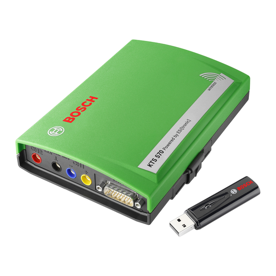
Bosch KTS 530 Produktbeschreibung
Für die steuergeräte-diagnose
Vorschau ausblenden
Andere Handbücher für KTS 530:
- Originalbetriebsanleitung (171 Seiten) ,
- Originalbetriebsanleitung (201 Seiten)
Inhaltsverzeichnis
Verfügbare Sprachen
Verfügbare Sprachen
KTS 530 / KTS 540 / KTS 570
de Produktbeschreibung
Modul für die Steuergeräte-Diagnose
es Descripción del Producto
Módulo para el diagnóstico de la unidad
de control
pt Descrição do produto
Módulo de diagnóstico de unidades de
comando
en Product description
Module for controller diagnosis
it Descrizione del prodotto
Modulo per la diagnosi di centraline di
comando
fr Description de produit
Module pour le diagnostic des centrales
de commande
sv Produktbeskrivning
Modul för styrdonsdiagnosen
Kapitel
Inhaltsverzeichnis

Verwandte Anleitungen für Bosch KTS 530


Inhaltszusammenfassung für Bosch KTS 530
- Seite 1 KTS 530 / KTS 540 / KTS 570 de Produktbeschreibung en Product description fr Description de produit Modul für die Steuergeräte-Diagnose Module for controller diagnosis Module pour le diagnostic des centrales de commande es Descripción del Producto it Descrizione del prodotto sv Produktbeskrivning Módulo para el diagnóstico de la unidad...
- Seite 3 | ��S ��� � ��S ��� � ��S ��� | � ��S ��� � ��S ��� � ��S ��� | � | � Inhaltsverzeichnis Deutsch � Contents Englisch 1� Sommaire Français �� Índice Español �� Indice Italiano �6 Innehål Svenska Contéudo Português Robert Bosch GmbH 1 689 979 987 2008-07-02...
-
Seite 4: Inhaltsverzeichnis
� | ��S ��� � ��S ��� � ��S ��� | Inhaltsverzeichnis �. Erstinbetriebnahme 1� ESI[tronic] Software-Installation Verwendete Symbolik � Anschluss Dokumentation Modulkonfiguration (DDC) KTS 530 / KTS 540 / KTS 570 Montage Befestigungshalter Benutzerhinweise � �. Instandhaltung 1� Wichtige Hinweise Reinigung Sicherheitshinweise Wartung Elektromagnetische Verträglichkeit (EMV) -
Seite 5: Verwendete Symbolik
2.� Elektromagnetische Verträglichkeit (EMV) leichten Körperverletzungen oder zu größe- ren Sachschäden führen könnte. KTS 530 / KTS 540 / KTS 570 ist ein Erzeugnis der Klasse A nach EN 55 022. Achtung – warnt vor möglicherweise schädlichen Si- KTS 530 / KTS 540 / KTS 570 kann im Wohnbereich tuationen, bei der KTS 530 / KTS 540 / KTS 570, der Funkstörungen verursachen;... -
Seite 6: Einschränkungen Bluetooth
Hindernisse, wie z. B. Stahltüren und Betonwände, das Funksignal von und zum KTS 530 / KTS 540 / KTS 570 stören können. Steht der PC in einem Bosch-Fahrwagen (z. B. FSA 740, BEA 850) sollte der Bluetooth-USB-Adapter mit einer USB-Verlängerungsleitung außerhalb des... -
Seite 7: Gerätebeschreibung
Voraussetzungen �.1 Verwendung �.2.1 Hardware KTS 530, KTS 540 und KTS 570 (nachfolgend als KTS- PC/Laptop mit mindestens einer freien USB-Schnittstelle. Module bezeichnet) sind Module zur Steuergeräte-Dia- gnose. Die Funktionsunterschiede entnehmen Sie der KTS-Module können bei folgenden Bosch-Produkten folgenden Tabelle:... -
Seite 8: Lieferumfang
Systemtester KTS 570 1 687 022 994 DIAG max. 60V Bluetooth-USB-Adapter (KTS 540/KTS 570) 1 687 023 449 OBD-Diagnoseleitung 3 m (KTS 530) 1 684 465 557 OBD-Diagnoseleitung 1,5 m 1 684 465 555 (KTS 540/KTS 570) 459802/12 Ko UNI-Anschlussleitung 4-polig... -
Seite 9: Statusanzeige Led A Und Led B
Nur der im Lieferumfang beigelegte Bluetooth- Blinkt grün USB-Adapter ermöglicht die Funkverbindung zu (1 Sekunden-Takt) KTS 530 / KTS 540 / KTS 570. Er wird am PC/Laptop Datenkommuni- Blinkt grün Blinkt grün eingesteckt und zeigt durch die blickende blaue LED die kation mit dem (unregelmäßig) -
Seite 10: Bedienung
1� | ��S ��� � ��S ��� � ��S ��� | Gerätebeschreibung �.� Bedienung �.�.2 Hinweise Steuergeräte-Diagnose KTS 530 kann nur über die USB-Schnittstelle mit PC/ KTS-Module werden entweder über das mitgelieferte Laptop verbunden werden. Netzteil oder über die OBD-Schnittstelle des Kraftfahr- KTS 540 und KTS 570 können über Funk (Bluetooth) zeugs mit Spannung versorgt. -
Seite 11: Hinweise Zu Multimeter Und Oszilloskop
U-, R- oder I- der Kommunikation mit dem Steuergerät wurde keine Dia- Messungen eine Masseverbindung von gnosehardware (KTS 530 / KTS 540 / KTS 570) gefunden. den KTS-Modulen (Fig. 1, Pos. 2) mit Es erscheint die Störungsmeldung "Diagnosehardware beiliegender Masseleitung an die Fahr- anschließen und mit externer Spannung versorgen"... -
Seite 12: Bluetooth-Treiber-Initialisierung
<Neue Verbindung> wählen, danach weiter bei Punkt 4. oder 3. Ist ein KTS 530 / KTS 540 / KTS 570 eingetragen: KTS 530 / KTS 540 / KTS 570 löschen. Wenn KTS 530 / KTS 540 / KTS 570 verbunden Im Dialogfenster "... -
Seite 13: Erstinbetriebnahme
Bluetooth-Hardware dient zur Konfiguration, Aktivierung und zum Test zu betreiben, da dadurch die Datenkommunikation von KTS-Modulen. zwischen KTS 530 / KTS 540 / KTS 570 und dem Steuergerät gestört wird. DDC starten (" Start >> Einstellungen >> System- steuerung"). -
Seite 14: Instandhaltung
Reinigung ermöglicht das Befestigen und Lösen des KTS-Moduls an einen Bosch-Fahrwagen (nur ab Fertigungsdatum Das Gehäuse des KTS 530 / KTS 540 / KTS 570 nur mit 03-2006 möglich). weichen Tüchern und neutralen Reinigungsmitteln rei- nigen. Keine scheuernden Reinigungsmittel und keine Die im Lieferumfang beiliegenden drei Linsenschrau- grobe Werkstattputzlappen verwenden. -
Seite 15: 6. �Echnische Daten
±0,75 % vom Messwert zusätzlich ±0,25 % vom Messbereich Genauigkeit bis 1 M ±2 % vom Messwert zusätzlich ±0,25 % vom Messbereich 0,1 — 1000 Auflösung (je nach Messbereich) Eingangswiderstand > 9 M Robert Bosch GmbH 1 689 979 987 2008-07-02... -
Seite 16: 6.6 Bluetooth Class
Bluetooth Class 1 Funkverbindung Mindest-Reichweite ��S ��� � ��S ��� � ��S ��� zu PC� Laptop Werkstattumgebung im Freifeld 30 Meter Bei offener Fahrzeugtür oder offenem 10 Meter Fahrzeugfenster und laufendem Motor im Fahrzeuginnenraum 1 689 979 987 2008-07-02 Robert Bosch GmbH... - Seite 96 Robert Bosch GmbH Diagnostics Franz-Oechsle-Straße 4 73207 Plochingen DEUTSCHLAND www.bosch.com bosch.prueftechnik@bosch.com Printed in Germany / Imprimé en Allemagne 1 689 979 987 | 2008-07-02...