
Verwandte Anleitungen für Klarstein Ion Breeze


Inhaltszusammenfassung für Klarstein Ion Breeze
- Seite 1 Ion Breeze Klimaanlage Air Conditioner Aire acondicionado Climatiseur Condizionatore d’aria 10033481...
-
Seite 3: Inhaltsverzeichnis
Sehr geehrter Kunde, wir gratulieren Ihnen zum Erwerb Ihres Gerätes. Lesen Sie die folgenden Hinweise sorgfältig durch und befolgen Sie diese, um möglichen Schäden vorzubeugen. Für Schäden, die durch Missachtung der Hinweise und unsachgemäßen Gebrauch entstehen, übernehmen wir keine Haftung. Scannen Sie den folgenden QR-Code, um Zugriff auf die aktuellste Bedienungsanleitung und weitere Informationen rund um das Produkt zu erhalten. -
Seite 4: Sicherheitshinweise
SICHERHEITSHINWEISE • Lesen Sie sich alle Hinweise sorgfältig durch und bewahren Sie die Bedienungsanleitung zum Nachschlagen gut auf. • Benutzen Sie die Klimaanlage nur in Innenräumen. • Schließen Sie das Gerät nur an Steckdosen an, die der Spannung des Geräts entsprechen. -
Seite 5: Hinweise Zum Kältemittel R290
HINWEISE ZUM KÄLTEMITTEL R290 Warnhinweise • Die Klimaanlage muss aufrecht aufbewahrt und transportiert werden. Andernfalls können irreparable Kompressorschäden entstehen. Lassen Sie das Gerät im mindestens 24 Stunden stehen, bevor Sie es in Betrieb nehmen. • Schalten Sie den das Gerät vor der Reinigung aus und trennen Sie es von der Stromversorgung. -
Seite 6: Geräteübersicht
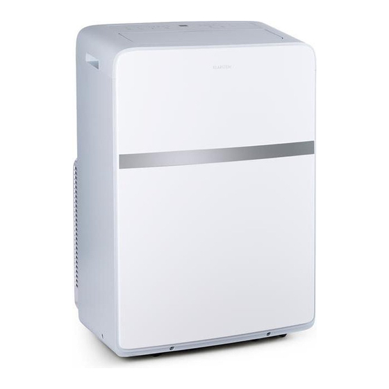
GERÄTEÜBERSICHT Vorderseite Bedienfeld Luftauslass Tragegriff Vordere Abdeckung Luftauslass Rückseite Tragegriff Oberer Luftfilter Oberer Lufteinlass Wasserauslass Luftauslass Unterer Luftfilter Unterer Lufteinlass Netzanschluss Pumpenauslass Kabelhalterung Unterer Auslass der Bodenwanne... -
Seite 7: Bedienfelder Und Tastenfunktionen
BEDIENFELD UND TASTENFUNKTIONEN Je nach Modell verfügt das Gerät über eines der beiden Bedienfelder: Temperaturanzeige Temperaturanzeige Temperaturanzeige • Wenn Sie sich im Kühlmodus befinden und auf (+] oder [-] drücken, ändert sich die Temperatur und die eingestellte Temperatur wird in der Temperaturanzeige angezeigt. - Seite 8 (3) FAN-SPEED-Taste: Drücken Sie die mehrmals auf die Taste, um die Lüftergeschwindigkeit in der folgenden Reihenfolge einzustellen: AUTO > HI (hoch) > MED (mittel) > LOW (niedrig) > AUTO. Die Anzeigen über der Taste, zeigen die eingestellte Geschwindigkeit an. Hinweis: Im FAN-Modus kann die Geschwindigkeit nicht auf AUTO gestellt werden. (4) Tasten (+) und (-): Jedes Mal wenn Sie eine der beiden Tasten drücken erhöht oder verringert sich die Temperatur um 1 °C (1 °F).
-
Seite 9: Inbetriebnahme Und Bedienung
INBETRIEBNAHME UND BEDIENUNG Wichtige Hinweise • Der Stecker muss in eine separate Steckdose gesteckt werden, an der keine anderen Geräte angeschlossen sind. • Verwenden Sie kein Verlängerungskabel. Vor dem Betrieb • Suchen Sie sich einen geeigneten Standort in der Nähe einer Steckdose. •... -
Seite 10: Auto-Restart
FAN-Modus • Drücken Sie auf die MODE-Taste, bis die FAN-Anzeige leuchtet. • Drücken Sie auf die FAN-Taste, um die gewünschte Geschwindigkeit einzustellen. Hinweis: Die Temperatur kann in diesem Modus nicht eingestellt werden. AUTO-RESTART-Funktion Wenn die Stromversorgung des Geräts unterbrochen wird, startet das Gerät nach dem Wiedereinschalten in seinem zuletzt verwendeten Modus mit den letzten Einstellungen. - Seite 11 Teil Beschreibung Stk. Schaumstoffdichtung Typ B (nicht klebend) Adapter B* (rundes Ende), 1 Set Wandauslass-Adapter* Abflussrohr Fernbedienung mit Batterie Hinweis: Die mit einem Stern (*) gekennzeichneten Teile werden nicht bei allen Geräten standardmäßig mitgeliefert. Bestimmung eines geeigneten Standorts • Installieren Sie das Gerät an einem flachen und geräumigen Ort, an dem die Luftauslässe nicht behindert werden.
- Seite 12 Installation des Abluftrohrs Wenn Sie die Modi COOL, und DRY verwenden, muss das Abluftrohr installiert werden. Für den FAN-Modus muss das Abluftrohr nicht installiert werden. Je nach Bedarf kann das flexible Abluftrohr mäßig komprimiert und gespannt, aber nicht beliebig gestreckt und gebogen werden. Das Abluftrohr kann mit einem Fenster verbunden oder in die Wand eingebaut werden.
- Seite 13 Installation des Schiebefenster-Sets Horizontal Vertikal Schaumstoff- dichtung A Fensterflügel Schneiden Sie die Schaumstoffdichtung (klebend) auf die richtige Länge und befestigen Sie sie am Fensterflügel. Schraube A Schiebefenster-Set Befestigen Sie das Schiebefenster-Set am Fensterflügel. Passen Sie die Länge des Sets an, indem Sie die Schraube A lösen und die Länge einstellen. Wenn Sie die Länge korrekt eingestellt haben, ziehen Sie die Schraube wieder an.
- Seite 14 Schraube B Senken Sie das Fenster vorsichtig ab. Befestigen Sie das Schiebefenster-Set mit 4 Schrauben Typ B und je einer Schraube für jede Verlängerung. Schaumstoff- dichtung Schneiden Sie die Schaumstoffdichtung B (nicht klebend) auf die Fensterbreite zu. Befestigen Sie die Schaumstoffdichtung B zwischen Glas und Fenster, damit keine Luft und Insekten in den Raum gelangen.
- Seite 15 Installation des Abluftrohrs am Fenster Bewegen Sie das Gerät mit installiertem Abluftrohr in die Nähe des Fensters und verbinden sie den Adapter B (flaches Ende) mit dem Fenster. Installation des Abluftrohrs an der Wand Bereiten Sie das Loch in der Wand vor. Montieren Sie den Wandadapter im Loch an der Wand.
- Seite 16 Hinweis: Der Kanal kann auf min. 270 mm komprimiert und auf max. 1500 mm verlängert werden. Es ist besser, die Rohrlänge auf ein Minimum zu beschränken. Ein übermäßiges Strecken oder Biegen des Kanals beeinträchtigt die Kühlleistung. Installation ohne Schiebefenster-Set Wenn Sie weder über Schiebefenster, noch über einen Wandauslass verfügen und Adapter B wie auf dem unteren Bild aussieht, öffnen Sie das Fenster ein kleines Stück und befestigen Sie das Abluftrohr wie dargestellt.
-
Seite 17: Installtion Des Wasserablaufs
INSTALLATION DES WASSERABLAUFS Bevor Sie den DRY-Modus (Entfeuchtungsmodus) verwenden, entfernen Sie die obere Ablassschraube auf der Rückseite des Gerätes. Befestigen Sie den Ablaufschlauch am Wasserauslass. Legen Sie das andere Ende des Schlauches in einen Abfluss oder ein Sammelgefäß. Wasserauslass Wenn das von Ihnen gekaufte Gerät den Pumpenauslass hat (wie unten gezeigt), installieren Sie den Wasserablauf wie folgt: Entfernen Sie die Pumpenablassschraube von der Rückseite des Gerätes und befestigen Sie den Ablassschlauch an der Bohrung. -
Seite 18: Reinigung Und Pflege
Wenn der Wasserstand der Bodenwanne ein vorgegebenes Niveau erreicht, zeigt das Display [P1] an und die Anzeige WATER FULL leuchtet auf. Bewegen Sie das Gerät vorsichtig zu einem Abfluss, entfernen Sie die untere Ablassschraube und lassen Sie das Wasser abfließen. Schließen Sie die untere Ablassschraube und starten Sie die Maschine neu. - Seite 19 Reinigung der Luftfilter Nehmen Sie den oberen und den unteren Luftfilter, wie auf Bild 1 und Bild 2 dargestellt. Falls der untere Lufteinlass mit einer Schraube gesichert ist, entfernen Sie zuerst die Schraube. Reinigen Sie die Luftfilter mit dem Staubsauger oder waschen Sie sie in einer milder Seifenlauge ab.
- Seite 20 Wartung des Kältmittel-Systems VORSICHT Verletzungsgefahr! Wartungs- oder Reparaturarbeiten am Kältmittel- System dürfen nur von autorisierten Fachbetrieben und geschulten Fachkräften ausgeführt werden. Die Wartung durch unqualifi zierte Personen kann zu Verletzungen und zur Beschädigung des Kältmittel- Systems führen! FEHLERBEHEBUNG Problem Mögliche Ursache Lösungsansatz Das Gerät läuft nicht.
-
Seite 21: Hinweise Zur Entsorgung
Problem Mögliche Ursache Lösungsansatz Geräusche oder Der Untergrund ist nicht Stellen Sie das Gerät auf Vibrationen. eben oder zu stark einen ebenen Untergrund, geneigt. der maximal um 10° geneigt ist. Wenn Sie die POWER- Seit dem Ausschalten sind Warten Sie vier Minuten. Taste drücken geht das noch keine 4 Minuten Gerät nicht an. -
Seite 22: Konformitätserklärung
KONFORMITÄTSERKLÄRUNG Hersteller: Chal-Tec GmbH, Wallstraße 16, 10179 Berlin, Deutschland. Dieses Produkt entspricht den folgenden Europäischen Richtlinien: 2014/30/EU (EMV) 2014/35/EU (LVD) 201 1/65/EU (RoHS) 206/2012/EU (ErP) -
Seite 23: Technical Data
Dear Customer, Congratulations on purchasing this equipment. Please read this manual carefully and take care of the following hints to avoid damages. Any failure caused by ignoring the items and cautions mentioned in the instruction manual is not covered by our warranty and any liability. Scan the QR code to get access to the latest user mannual and other information about the product. -
Seite 24: Safety Instructions
SAFETY INSTRUCTIONS • Read all instructions carefully and keep the operating instructions in a safe place for future reference. • Only use the air conditioner indoors. • Only connect the appliance to an outlet that corresponds to the voltage of the appliance. -
Seite 25: Notes On Refrigerant R290
NOTES ON REFRIGERANT R290 Warnings • The air conditioning system must be kept and transported upright. Otherwise, irreparable compressor damage may occur. Leave the unit for at least 24 hours before putting it into operation. • Switch off the device and disconnect it from the power supply before cleaning. •... -
Seite 26: Product Overview
PRODUCT OVERVIEW Front Control panel Air outlet Carrying handle Front panel Air outlet Rear Carrying handle Upper air filter Upper air intake Drain outlet Air outlet Lower air filter Lower air filter Power plug socket Pump drain socket Power cord buckle Bottom tray drain outlet... -
Seite 27: Control Panel And Key Functions
CONTROL PANEL AND KEY FUNCTIONS Depending on the model, the device has one of the two control panels: Temperature indicator Temperature indicator Temperature indicator • When you are in cooling mode and press (+) or (-), the temperature changes and the set temperature is displayed in the temperature display. - Seite 28 (3) FAN-SPEED button: Press the button repeatedly to set the fan speed in the following order: AUTO > HI > MED > LOW > AUTO. The inicator above the button indicates the set speed. Note: In FAN mode, the speed cannot be set to AUTO. (4) Buttons (+) and (-): Each time you press one of these buttons, the temperature increases or decreases by 1°C (1°F).
-
Seite 29: Start-Up And Operation
START-UP AND OPERATION Important notes • The plug must be plugged into a separate socket to which no other devices are connected. • Do not use an extension cord. Before first use • Find a suitable location near an electrical outlet. •... -
Seite 30: Installing The Exhaust Duct
FAN mode • Press the MODE button until the FAN indicator lights. • Press the FAN button to set the desired speed. Note: The temperature cannot be set in this mode. AUTO RESTART Function If the power supply to the unit is interrupted, the unit will restart in its last used mode with the last settings after it has been switched back on. - Seite 31 Part Description Type B foam seal (non-adhesive) Adaptor B (round mouth)*, 1 Set Wall exhaust Adaptor* Drain hose Remote controller and Battery Note: The parts marked with a star (*) are not supplied as standard with all devices. Determination of a suitable location •...
- Seite 32 Installation of the exhaust duct When using the COOL and DRY modes, the exhaust duct must be installed. In FAN mode, the exhaust duct does not need to be installed. Depending on requirements, the flexible exhaust duct can be moderately compressed and tensioned, but not arbitrarily stretched and bent.
- Seite 33 Install the window slider kit Horizontal Vertical Foam seal A window sash Cut the foam seal(adhesive type) to the proper length and attach it to the window sash. Screw A window slider kit Attach the window slider kit to the window sash. Adjust the length of the Window Slider Kit: Loose the screw A to adjust the length of the Window Slider Kit, then tight the screw when the length is suitable.
- Seite 34 Screw B Carefully lower the window. Secure the vent panel in place with 4 type B screws,plus one screw for each extension. Foam seal Cut the foam seal B(non-adhesive) to the window width. Stuff the foam seal B between the glass and the window to prevent air and insects from getting into room. lnstall the security bracket with a type B screw, as shown.
- Seite 35 Install the exhaust duct into the window Remove the unit with the packed exhaust duct next to the window, and then connect the adaptors (flat mouth) of the exhaust duct with the window. Install the exhaust duct into the wall Prepare a hole in the wall.
- Seite 36 Note: The duct can be compressed to 270 mm minimum and extended to 1500 mm maximum. It is better to keep the duct length to a minimum. Stretching or bending the duct excessively will affect the cooling efficiency. Installation without sliding window set If you have neither a sliding window nor a wall outlet and adapter B looks as shown in the picture below, open the window a little and attach the exhaust pipe as shown.
-
Seite 37: Installtion Of The Water Drainage
INSTALLTION OF THE WATER DRAINAGE Before using DRY mode, remove the upper drain plug on the back of the unit. Attach the drain hose to the water outlet. Place the other end of the hose in a drain or collection vessel. -
Seite 38: Cleaning And Care
When the water level of the floor pan reaches a preset level, the display shows [P1] and the WATER FULL indicator lights up. Carefully move the unit to a drain, remove the lower drain plug and drain the water. Close the lower drain plug and restart the machine. - Seite 39 Cleaing the air filters Take the upper and lower air filters as shown in Figure 1 and Figure 2. If the lower air inlet is secured with a screw, first remove the screw. Clean the air filters with a vacuum cleaner or wash them in a mild soapy water solution.
-
Seite 40: Troubleshooting
Maintenance of the refrigerant system CAUTION Risk of injury! Maintenance or repair work on the refrigerant system may only be carried out by authorised specialist companies and trained specialists. Maintenance by unqualifi ed persons can lead to injuries and damage to the refrigerant system! TROUBLESHOOTING Problem Possible cause... -
Seite 41: Hints On Disposal
Problem Possible cause Suggested solution Noises or vibrations. The surface is not level or Place the unit on a level too inclined. surface with a maximum inclination of 10°. When you press the Less than 4 minutes have Wait four minutes. POWER button, the unit elapsed since the unit was does not turn on. -
Seite 42: Declaration Of Conformity
DECLARATION OF CONFORMITY Producer: Chal-Tec GmbH, Wallstraße 16, 10179 Berlin, Germany. This product is conform to the following European Directives: 2014/30/EU (EMC) 2014/35/EU (LVD) 201 1/65/EU (RoHS) 206/2012/EU (ErP) -
Seite 43: Datos Técnicos
Estimado cliente: Le felicitamos por la adquisición de este producto. Lea atentamente el siguiente manual y siga cuidadosamente las instrucciones de uso con el fin de evitar posibles daños. La empresa no se responsabiliza de los daños ocasionados por un uso indebido del producto o por haber desatendido las indicaciones de seguridad. -
Seite 44: Indicaciones De Seguridad
INDICACIONES DE SEGURIDAD • Lea atentamente todas las indicaciones y conserve este manual para consultas posteriores. • Utilice el aire acondicionado solamente en espacios interiores. • Conecte el aparato solamente a tomas de corriente que se adecuen a la tensión del mismo. -
Seite 45: Indicaciones Sobre El Refrigerante R290
INDICACIONES SOBRE EL REFRIGERANTE R290 Advertencias • Transporte y guarde el aparato en posición vertical. De lo contrario, podría dañar de forma irreparable el compresor. Deje el aparato en posición vertical durante al menos 24 horas antes de ponerlo en marcha. •... -
Seite 46: Visión General Del Aparato
VISIÓN GENERAL DEL APARATO Vorderseite Panel de control Parte delantera Asa de transporte Cubierta delantera Salida de aire Parte trasera Asa de transporte Filtro de aire superior Entrada de aire superior Salida de agua Salida de aire Filtro de aire inferior Conexión para Entrada de aire... -
Seite 47: Panel De Control Y Botones
PANEL DE CONTROL Y BOTONES En función del modelo, el aparato dispondrá de uno de estos dos paneles de control: Indicador de temperatura Indicador de temperatura Indicador de temperatura • Si se encuentra en modo refrigeración o calefacción y pulsa [+] o [-], la temperatura se modifica y aparece la temperatura configurada en el indicador. - Seite 48 (3) Botón FAN-SPEED: pulse varias veces el botón para regular la velocidad del ventilador en el siguiente orden: AUTO > HI (alta) > MED (media) > LOW (baja) > AUTO. Los indicadores situados encima de los botones muestran la velocidad seleccionada.
-
Seite 49: Puesta En Marcha Y Uso
PUESTA EN MARCHA Y USO Indicaciones importantes • El enchufe debe conectarse a una toma de corriente por separado donde no existan otros aparatos. • No utilice un cable alargador. Antes de su uso • Busque un lugar adecuado para su ubicación, a ser posible cerca de una toma de corriente. -
Seite 50: Instalación Del Conducto De Extracción
Modo FAN • Pulse el botón MODE hasta que se ilumine el indicador FAN. • Pulse el botón FAN y ajuste la velocidad deseada. Nota: En este modo no puede ajustarse la temperatura. Función AUTO-RESTART Si se interrumpe el suministro eléctrico del aparato, este se reinicia cuando se encienda de nuevo en el último modo utilizado con los ajustes seleccionados. - Seite 51 Pieza Descripción Uds. Junta de espuma tipo B (no adhesiva) Adaptador B* (extremo redondo), 1 juego Adaptador de salida en pared* Conducto de extracción Mando a distancia con pilas Nota: Las piezas señaladas con un asterisco (*) no se entregan en todos los aparatos de manera estándar.
- Seite 52 Instalación del conducto de extracción Si utiliza los modos COOL y DRY debe instalar el conducto de extracción. Para modo FAN no es necesario instalar el conducto de extracción. En función de sus necesidades, el conducto de extracción flexible puede comprimirse y tensarse, pero es mejor que no esté...
- Seite 53 Instalación del set de ventana corredera Horizontal Vertical Junta de espuma A Hoja de la ventana Corte la junta de espuma (adhesiva) en el largo correcto y péguela a la hoja de la ventana. Tornillo A Set de ventana corredera Fije el set de ventana corredera en la hoja de la ventana.
- Seite 54 Tornillo B Baje con cuidado la ventana. Fije el set de ventana corredera con 4 tornillos del tipo B y un tornillo para cada prolongación. Junta de espuma Corte la junta de espuma B (no adhesiva) con el ancho de la ventana. Fije la junta de espuma B entre el cristal y la ventana para que no entre aire ni insectos a la estancia.
- Seite 55 Instalación del conducto de extracción en la ventana Mueva el aparato con el conducto de extracción instalado cerca de la ventana y conecte el adaptador B (extremo plano) a la ventana. Instalación del conducto de extracción a la pared Prepare el orificio en la pared. Monte el adaptador de pared en el orificio de la pared. Fije a continuación el conducto de extracción en el adaptador de pared.
- Seite 56 Nota: El canal se puede comprimir a un mínimo de 270 mm y expandir a un máximo de 1500 mm. Se recomienda limitar al mínimo el largo del conducto. Una extensión o curvatura excesivas del canal afectará negativamente a la potencia de refrigeración.
-
Seite 57: Instalación Del Conducto De Desagüe
INSTALACIÓN DEL CONDUCTO DE DESAGÜE Antes de utilizar el modo DRY (modo deshumidificación), retire los tapones de desagüe superiores situados en la parte trasera del aparato. Fije el conducto de evacuación al desagüe. Coloque en el otro extremo del conducto en un desagüe o en un recipiente colector. -
Seite 58: Limpieza Y Cuidado
Si el nivel del agua del recipiente del suelo presenta un determinado nivel, el display muestra [P1] y el indicador WATER FULL se ilumina. En ese caso, mueva el aparato con cuidado hacia un desagüe, retire los tapones de desagüe y deje que el agua se drene. - Seite 59 Limpieza del filtro de aire Coja el filtro de aire inferior y superior como se muestra en la imagen 1 y 2. Si la entrada de aire está asegurada con un tapón, retire primero el tapón. Lave el filtro con agua y jabón o límpielo con la aspiradora. Aclárelo con agua limpia y deje que se seque completamente.
-
Seite 60: Resolución De Problemas
Mantenimiento del sistema de refrigeración ATENCIÓN Riesgo de lesiones. Los trabajos de mantenimiento y reparación en el sistema de refrigeración deben ser realizados solamente por personal cualifi cado y autorizado. El mantenimiento realizado por una persona no cualifi cada puede provocar lesiones y daños en el sistema de refrigeración. -
Seite 61: Retirada Del Aparato
Problema Posible causa Solución propuesta Sonidos y vibraciones. La base no es regular o Coloque el aparato en presenta una inclinación una superficie plana con pronunciada. una inclinación máxima de 10°. El aparato no se enciende Desde que se apagó Espere 4 minutos. -
Seite 62: Declaración De Conformidad
DECLARACIÓN DE CONFORMIDAD Fabricante: Chal-Tec GmbH, Wallstraße 16, 10179 Berlín (Alemania). Este producto cumple con las siguientes directivas europeas: 2014/30/UE (EMC) 2014/35/UE (baja tensión) 201 1/65/UE (refundición RoHS) 206/2012/UE (ErP) -
Seite 63: Fiche Technique
Chère cliente, cher client, Toutes nos félicitations pour l’acquisition de ce nouvel appareil. Veuillez lire attentivement et respecter les instructions de ce mode d’emploi afin d’éviter d’éventuels dommages. Le fabricant ne saurait être tenu pour responsable des dommages dus au non- respect des consignes de sécurité... -
Seite 64: Consignes De Sécurité
CONSIGNES DE SÉCURITÉ • Lisez attentivement toutes les consignes et conservez ce mode d‘emploi en lieu sûr afin de pouvoir vous y référer ultérieurement. • Utilisez le climatiseur à l‘intérieur uniquement. • Ne branchez l‘appareil que sur des prises dont la tension correspond à celle de l‘appareil. -
Seite 65: Remarques Concernant Le Réfrigérant R290
REMARQUES CONCERNANT LE RÉFRIGÉRANT R290 Mises en garde • Le climatiseur doit être entreposé et transporté à la verticale. Faute de quoi, le compresseur pourrait être endommagé de façon irréparable. En cas de doute, laissez l‘appareil reposer pendant au moins 24 heures avant de le mettre en service. -
Seite 66: Aperçu De L'appareil
APERÇU DE L‘APPAREIL Face avant Panneau de contrôle Sortie d‘air Poignée de transport Cache avant Sortie d‘air Dos de l‘appareil Poignée de transport Filtre à air supérieur Prise d‘air supérieure Sortie d‘eau Sortie d‘air Filtre à air inférieur Raccordement au Prise d‘air secteur inférieure... -
Seite 67: Panneau De Commande Et Touches
PANNEAU DE COMMANDE ET TOUCHES En fonction des modèles, votre appareil dispose de l‘un des deux panneaux de commande suivants : Affichage de la température Affichage de la température Affichage de la température • Lorsque vous êtes en mode de climatisation et que vous appuyez sur [+] ou [-], la température change et la température réglée s‘affiche à... - Seite 68 (3) Touche FAN-SPEED : appuyez plusieurs fois sur la touche pour régler la vitesse du ventilateur dans l‘ordre suivant : AUTO > HI (élevée) > MED (moyenne) > LOW (basse) > AUTO. Les témoins au-dessus de la touche indiquent la vitesse sélectionnée.
-
Seite 69: Mise En Marche Et Utilisation
MISE EN MARCHE ET UTILISATION Remarques importantes • La fiche doit être branchée seule sur une prise, sans aucun autre appareil connecté. • Ne pas utiliser de rallonge. Avant l‘utilisation • Choisissez un endroit approprié près d‘une prise de courant. •... -
Seite 70: Installation Du Tuyau D'extraction
Mode FAN • Appuyez sur le bouton MODE jusqu‘à ce que le témoin FAN s‘allume. • Appuyez sur le bouton FAN pour régler la vitesse souhaitée. Remarque : dans ce mode, vous ne pouvez pas modifier la température. Fonction AUTO-RESTART Si l‘alimentation de l‘appareil est interrompue, il redémarrera avec les derniers réglages dans le dernier mode utilisé. - Seite 71 Pièce Description qté. Joint en mousse de type B (non adhésif) Adaptateur B* (bout rond), Adaptateur 1 Set de sortie d'air murale * Tuyau d'évacuation Télécommande avec pile Remarque : les pièces signalées par un astérisque (*) ne sont pas livrées avec tous les appareils.
- Seite 72 Installation du tuyau d‘extraction Lorsque vous utilisez les modes COOL et DRY, le tuyau d‘extraction doit être installé. Pour le mode FAN, le tuyau d‘extraction n‘a pas besoin d‘être installé. En fonction des besoins, le tuyau d‘extraction flexible peut être modérément comprimé et tendu, mais pas étiré...
- Seite 73 Installation du kit pour fenêtre coulissante horizontal vertical Joint de mousse A battant de fenêtre Coupez le joint en mousse (adhésif) à la longueur voulue et fixez-le à la fenêtre. Vis A Kit pour fenêtre coulissante Fixez le kit pour fenêtre coulissante sur le vantail. Ajustez la longueur du kit en desserrant la vis A et en ajustant la longueur.
- Seite 74 Vis B Abaissez la fenêtre avec précaution. Fixez le kit de fenêtre coulissante à l’aide de 4 vis de type B et d’une vis pour chaque rallonge. Joint de mousse Coupez le joint en mousse B (non adhésif) à la largeur de la fenêtre. Fixez le joint en mousse B entre la vitre et la fenêtre pour empêcher l’air et les insectes de pénétrer dans la pièce.
- Seite 75 Installation du tuyau d‘extraction sur la fenêtre Une fois le tuyau d‘extraction installé, placez l’appareil près de la fenêtre et connectez l’adaptateur B (extrémité plate) à la fenêtre. Installation du tuyau d‘extraction sur un mur Préparez le trou dans le mur. Montez l‘adaptateur mural dans le trou du mur. Fixez ensuite le tuyau d‘extraction sur l‘adaptateur mural.
- Seite 76 Remarque : Le conduit peut être comprimé à 270 mm minimum et étiré au max. à 1500 mm. Il est préférable de minimiser la longueur du tube. Un étirement ou une flexion excessif du conduit affectera les performances de climatisation. Installation sans le kit de fenêtre coulissante Si vous ne disposez ni d‘une fenêtre coulissante ni d‘une prise murale, et que l‘adaptateur B ressemble à...
-
Seite 77: Installation De L'évacuation D'eau
INSTALLATION DE L‘ÉVACUATION D‘EAU Avant d‘utiliser le mode DRY (mode déshumidification), retirez le bouchon de vidange supérieur à l‘arrière de l‘appareil. Fixez le tuyau de vidange à la sortie d‘eau. Placez l’autre extrémité du tuyau dans une évacuation ou un récipient collecteur. Sortie d‘eau Si l‘appareil que vous avez acheté... -
Seite 78: Nettoyage Et Entretien
Lorsque le niveau d‘eau du bassin de fond atteint un niveau prédéfini, l‘écran affiche [P1] et le témoin WATER FULL s‘allume. Déplacez délicatement l‘appareil vers une évacuation, retirez le bouchon de vidange inférieur et vidangez l‘eau. Fermez le bouchon de vidange inférieur et redémarrez l‘appareil. - Seite 79 Nettoyage du filtre à air Retirez les filtres à air supérieur et inférieur comme indiqué sur les schémas 1 et 2. Si l‘entrée d‘air inférieure est fixée avec une vis, retirez-la d‘abord. Nettoyez les filtres à air à l’aspirateur ou lavez-les avec une solution savonneuse douce.
-
Seite 80: Résolution Des Problèmes
Maintenance du système réfrigérant ATTENTION Risque de blessure ! Les travaux de maintenance ou de réparation sur le système de réfrigérant ne doivent être effectués que par des sociétés spécialisées autorisées et des spécialistes qualifi és. L‘entretien par des personnes non qualifi ées peut entraîner des blessures et endommager le système réfrigérant ! RÉSOLUTION DES PROBLÈMES Problème... -
Seite 81: Informations Sur Le Recyclage
Problème Cause possible Résolution Bruits ou vibrations. Le sol n'est pas bien plat Installez l'appareil sur un ou trop incliné. sol plat avec une pente maximale de 10°. Lorsque vous appuyez Il ne s'est pas encore Patientez quatre minutes. sur la touche POWER, écoulé... -
Seite 82: Déclaration De Conformité
DÉCLARATION DE CONFORMITÉ Fabricant : Chal-Tec GmbH, Wallstraße 16, 10179 Berlin, Allemagne. Ce produit est conforme aux directives européennes suivantes : 2014/30/UE (CEM) 2014/35/UE (LVD) 201 1/65/UE (RoHS) 206/2012/UE (ErP) -
Seite 83: Dati Tecnici
Gentile cliente, La ringraziamo per aver acquistato il dispositivo. La preghiamo di leggere attentamente le seguenti istruzioni per l’uso e di seguirle per evitare possibili danni tecnici. Non ci assumiamo alcuna responsabilità per danni scaturiti da una mancata osservazione delle avvertenze di sicurezza e da un uso improprio del dispositivo. -
Seite 84: Avvertenze Di Sicurezza
AVVERTENZE DI SICUREZZA • Leggere attentamente le seguenti avvertenze di sicurezza e conservare il presente manuale d’istruzioni per consultazioni future. • Utilizzare il dispositivo esclusivamente in ambienti interni. • Collegare il dispositivo solo a prese che corrispondono alla tensione indicata. •... -
Seite 85: Avvertenze Sul Refrigerante R290
AVVERTENZE SUL REFRIGERANTE R290 Avvertenze • Il climatizzatore deve essere conservato e trasportato in verticale, altrimenti possono risultare danni irreparabili al compressore. Lasciare il dispositivo in posizione verticale per almeno 24 ore prima di metterlo in funzione. • Spegnere il dispositivo e staccare la spina prima di pulirlo. •... -
Seite 86: Panoramica Del Prodotto
PANORAMICA DEL PRODOTTO Lato Frontale Panello di Controllo fuoriuscita aria Maniglia di Trasporto Panello Frontale Uscita dell‘aria Rückseite Maniglia di Trasporto Filtro aria superiore Presa d’aria superiore Uscita acqua Fuoriuscita aria Filtro aria inferiore Presa d‘aria Presa di corrente inferiore Presa di scarico della pompa Portacavo... -
Seite 87: Pannello Di Controllo E Funzioni Chiave
PANNELLO DI CONTROLLO E FUNZIONI CHIAVE Sulla base del modello, l’apparecchio presenta uno o due pannelli di controllo: Indicatore della Temperatura Indicatore della Temperatura Indicatore di temperatura • Quando ci si trova nella modalità di raffreddamento e si preme (+) o (-), la temperatura cambia e la temperatura impostata viene visualizzata sul display della temperatura. - Seite 88 (3) Tasto FAN-SPEED: premere ripetutamente il tasto per impostare la velocità del ventilatore nel seguente ordine: AUTO > HI (alto) > MED (medio) > LOW (basso) > AUTO. I display sopra il pulsante indicano la velocità impostata. Nota: In modalità FAN, la velocità non può essere impostata su AUTO. (4) (+) e (-): ogni volta che si preme uno dei due pulsanti, la temperatura aumenta o diminuisce di 1°C (1°F).
-
Seite 89: Avvertenze Importanti
Avvertenze importanti • La spina deve essere inserita in una presa separata alla quale non sono collegati altri apparecchi. • Non utilizzare prolunghe. Prima del primo utilizzo • Trovare una posizione adatta vicino a una presa elettrica. • Montare il tubo di scarico e la guarnizione della finestra come descritto nel capitolo „Montaggio del condotto di scarico“. -
Seite 90: Modalità Fan
Modalità FAN • Premere il pulsante MODE finché non si accende l‘indicatore FAN. • Premere il pulsante FAN per impostare la velocità desiderata. Nota: La temperatura non può essere impostata in questa modalità. Funzione AUTO RESTART (riavvio automatico) Se l‘alimentazione elettrica dell‘unità viene interrotta, l‘unità si riavvia nella sua ultima modalità... - Seite 91 Componenti Descrizione Pez. Guarnizione in Schiuma di Tipo B (non adesiva) Adattatore B*(estremità rotonda), 1 Set adattatore di uscita a parete* Tubo di scarico Telecomando con Batterie Nota: Le parti contrassegnate con un asterisco (*) non sono fornite con tutti i dispositivi.
- Seite 92 Installazione del condotto di scarico Quando si utilizzano le modalità RAFFREDDAMENTO e ASCIUGATURA, è necessario installare il condotto di scarico. In modalità FAN, non è necessario installare il condotto di scarico. A seconda delle esigenze, il condotto di scarico flessibile può essere moderatamente compresso e teso, ma non arbitrariamente allungato e piegato.
- Seite 93 Installare il kit di scorrimento della finestra Orizzontale Verticale Guarnizione in schiuma Anta della finestra Tagliare la guarnizione in schiuma (tipo adesivo) alla lunghezza corretta e fissarla all‘anta della finestra. vite A kit di scorrimento per le finestre Fissare il kit di scorrimento della finestra all‘anta della finestra. Regolare la lunghezza del kit di scorrimento finestra: Allentare la vite A per regolare la lunghezza del kit di scorrimento finestra, quindi stringere la vite quando la lunghezza è...
- Seite 94 vite B Abbassare con cautela la finestra. Fissare il pannello di sfiato in posizione con 4 viti di tipo B, più una vite per ogni prolunga. guarnizione in schiuma Tagliare la guarnizione in schiuma B (non adesiva) alla larghezza della finestra. Riempire la guarnizione in schiuma B tra il vetro e la finestra per evitare che l‘aria e gli insetti entrino nella stanza.
- Seite 95 Installare il condotto di scarico nella finestra. Rimuovere l‘apparecchio con il condotto di scarico imballato vicino alla finestra, quindi collegare gli adattatori (bocca piatta) del condotto di scarico con la finestra. Installare il condotto di scarico nella parete Effettuare un foro nella parete. Installare l’adattatore di scarico a parete sulla parete, accertarsi di fissarlo accuratamente.
- Seite 96 Nota: Il condotto può essere compresso a 270 mm minimo e prolungato a 1500 mm massimo. È meglio mantenere la lunghezza del condotto al minimo. L‘allungamento o la flessione eccessiva del condotto influisce sull‘efficienza di raffreddamento. Montaggio senza set di finestre scorrevoli Se non si dispone né...
-
Seite 97: Installazione Del Sistema Di Drenaggio Dell'acqua
INSTALLAZIONE DEL SISTEMA DI DRENAGGIO DELL‘ACQUA Prima di utilizzare la modalità DRY, rimuovere il tappo di scarico superiore sul retro dell‘unità. Collegare il tubo flessibile di scarico all‘uscita dell‘acqua. Posizionare l‘altra estremità del tubo flessibile in un contenitore di scarico o di raccolta. Uscita di scarico Se l‘apparecchiatura acquistata ha un‘uscita della pompa (come mostrato sotto), installare lo scarico dell‘acqua come segue: Rimuovere il tappo di scarico della pompa... -
Seite 98: Pulizia E Cura
Quando il livello dell‘acqua del fondo vasca raggiunge un livello preimpostato, il display visualizza [P1] e l‘indicatore WATER FULL si accende. Spostare con cautela il dispositivo in uno scarico, rimuovere il tappo di scarico inferiore e lasciare uscire l‘acqua. Chiudere il tappo di scarico inferiore e riavviare la macchina. - Seite 99 Pulizia dei filtri dell’aria Prendere i filtri dell‘aria superiore e inferiore come mostrato in Figura 1 e Figura 2. Se la presa d‘aria inferiore è fissata con una vite, rimuovere prima la vite. Pulire i filtri dell‘aria con un aspirapolvere o lavarli in una soluzione di acqua e sapone delicato.
-
Seite 100: Risoluzione Dei Problemi
Manutenzione del sistema refrigerante ATTENZIONE Pericolo di lesioni! I lavori di manutenzione o riparazione del sistema refrigerante devono essere eseguiti esclusivamente da ditte specializzate autorizzate e da personale qualifi cato. La manutenzione da parte di persone non qualifi cate può causare lesioni e danni all‘impianto! RISOLUZIONE DEI PROBLEMI Problema... -
Seite 101: Smaltimento
Problema Possibile Causa Risoluzione Suggerita Rumori o vibrazioni La superficie non è piana Posizionare l'apparecchio o troppo inclinata su una superficie piana con un'inclinazione massima di 10°. Quando si preme il tasto Sono trascorsi meno di 4 Attendere qualche minuto power l’unità... -
Seite 102: Dichiarazione Di Conformità
DICHIARAZIONE DI CONFORMITÀ Produttore: Chal-Tec GmbH, Wallstraße 16, 10179 Berlino, Germania. Questo prodotto è conforme alle seguenti direttive europee: 2014/30/UE (EMC) 2014/35/UE (LVD) 201 1/65/UE (RoHS) 206/2012/UE (ErP)