Exsys EX-44384 Anleitung
Vorschau ausblenden
Andere Handbücher für EX-44384:

Verwandte Anleitungen für Exsys EX-44384


Inhaltszusammenfassung für Exsys EX-44384
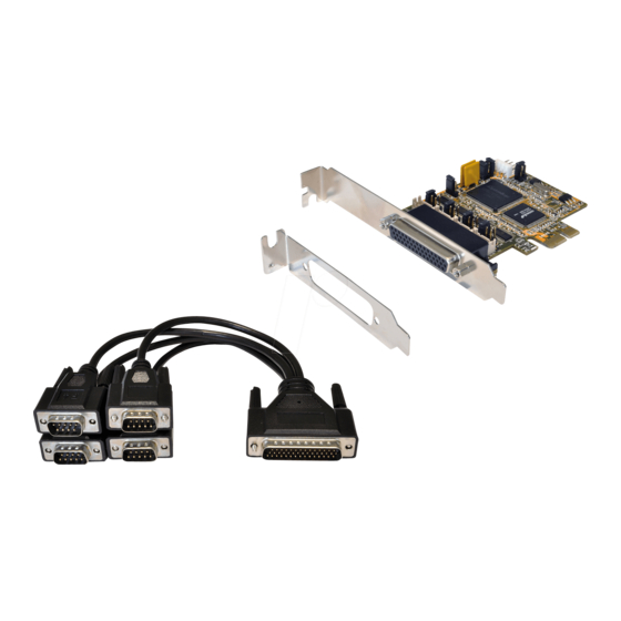
- Seite 1 Anleitung EX-44384 RS-232 PCI-e Karte mit 4 x 9 Pin Anschluss RS-232 PCI-e Card with 4 x 9 Pin Connector Vers. 1.0 / 01.08.18 Manual...
-
Seite 2: Inhaltsverzeichnis
Extent of Delivery ··············································································· 10 Layout & Connections ····································································· 11-12 3.1 Layout ····································································································· 11 3.2 Connections ························································································ 11-12 Jumper Settings ············································································ 12-13 Hardware Installation ··········································································· 14 Driver Information ·········································································· 14-16 Technical Information ·········································································· 16 © Copyright 2018 by EXSYS Vertriebs GmbH. All Rights Reserved... -
Seite 3: Beschreibung
System (BIOS) und vom Betriebssystem automatisch vorgenommen werden. Die EX-44384 bietet Ihnen die Möglichkeit, +5V und +12V auf Pin 1 und Pin 9 der seriel- len Anschlüsse zur Verfügung zu stellen. Es wird zusätzlich für den Einbau in schmale Computergehäuse ein 8 cm Low Profile Slot-Bügel mitgeliefert. -
Seite 4: Aufbau & Anschlüsse
1 DCD 2 RXD 2 RXD 3 TXD 3 TXD 4 DTR 4 DTR 5 GND 5 GND 6 DSR 6 DSR 7 RTS 7 RTS 8 CTS 8 CTS © Copyright 2018 by EXSYS Vertriebs GmbH. All Rights Reserved... -
Seite 5: Jumper-Einstellungen
= Die Funktion PME ist ausgeschaltet. (Werkseinstellung) = Die Funktion PME ist eingeschaltet. Der PC kann nun durch die Seriellen Ports der EX-44384 aktiviert werden. Dieser sollte aber bei Standard Anwendungen nicht verstellt werden. © Copyright 2018 by EXSYS Vertriebs GmbH. All Rights Reserved... -
Seite 6: Jumper Einstellung
4. Jumper Einstellungen S1~S4_PWR: S1~S4_PWR Jumper Einstellung Kein Power auf Pin1 oder Pin9 Pin1= DCD Pin9= RI (Werkseinstellung) +5V auf Pin1 +12V auf Pin1 +5V auf Pin9 +12V auf Pin9 © Copyright 2018 by EXSYS Vertriebs GmbH. All Rights Reserved... -
Seite 7: Hardware Installation
Ordner Ihres Betriebssystems aus und installieren Sie die Treiber (siehe Abbil- dung). Folgen Sie den Installationsanweisungen und schließen Sie die Installation ab. Wichtig! Starten Sie Ihren PC nach der Installation neu. © Copyright 2018 by EXSYS Vertriebs GmbH. All Rights Reserved... -
Seite 8: Überprüfen Des Installierten Treiber
ÜBERPRÜFEN DER INSTALLIERTEN TREIBER Öffnen Sie den >Geräte-Manager<. Jetzt müssten Sie unter „Anschlüsse (COM & LPT)“ und unter „Multifunktionsadapter“ folgende Einträge sehen: Sind diese oder ähnliche Einträge vorhanden, ist die Karte richtig installiert. © Copyright 2018 by EXSYS Vertriebs GmbH. All Rights Reserved... -
Seite 9: Technische Daten
0°C bis 55° Celsius Lagertemperatur: -40°C bis 75° Celsius Rel. Luftfeuchtigkeit: 5% bis 95% Stromversorgung: 5V oder 12V vom PC-Netzteil oder 12V vom Mainboard Abmessung: 89,00 x 66,00 mm Gewicht: 800g © Copyright 2018 by EXSYS Vertriebs GmbH. All Rights Reserved...