Exsys EX-44095 Bedienungsanleitung
EX-
EX
-
44095
44095
EX
-
44095
JUMPER SETTING & CONNECTORS:
JP3:
DIS
= The pin 9 is connected with the RI (Ring Indicator)
signal as standard RS-232 definition (Factory setting).
PWR
= The pin 9 is connected with a power either from PCI
Express slot or from Aux Power connector (J8) The power source is
controlled by JP4 jumper (see the following section).
JP4:
Only if JP3 is set to PWR! The pin 9 from the serial port connector
will be supplied with DC5V or DC12V. There are 3 sources depends
on the jumper position of JP4.
AUX5V = DC5V from J8, pc power supply cable is required
AUX5V
AUX12V
AUX12V = DC12V from J8, pc power supply cable is required
PCI12V
PCI12V = DC12V from PCI Express (Factory setting), no cable
J8:
1 +5V
For power over pc power supply J8 must be connected!
2 GND
3 GND
4 +12V
DB 9M:
Seriell 9 Pin D-SUB connector (S1 to S4):
Pin
Signal
Pin
1
CDC
4
2
RXD
5
3
TXD
6
DB 25F:
Parallel 25 female connector (P1):
Pin
Signal
Pin
1
STROBE
10
ACKNOWLEDGE
2
DATA 0
11
3
DATA 1
12
PAPER EMPTY
4
DATA 2
13
5
DATA 3
14
6
DATA 4
15
7
DATA 5
16
8
DATA 6
17
SELECT INPUT
9
DATA 7
18
HARDWARE INSTALLATION :
If you are ready with the jumper settings, please proceed with the following installation
instructions. Because the designs of computers are different, only general installation
instructions are given. Please refer your computer s reference manual whenever in doubt.
1. Turn off the power to your computer and any other connected peripherals.
2. Remove the mounting screws located at the rear and/or sides panels of your Com-
puter and gently slide the cover off.
3. Locate an available expansion slot and remove its covers from the rear panel of your
computer. Make sure it is the right expansion slot for the card (see card description)
4. Align the card with the expansion slot, and then gently but firmly, insert the card.
Make sure the card is seated and oriented correctly. Never insert the card by force!
5. Then connect the card with a screw to the rear panel of the computer case.
6. Gently replace your computer s cover and the mounting screws.
5
English
English
EX-
EX
-
44095
44095
English
EX
-
44095
DRIVER INSTALLATION :
Windows 9x/ME/2000/XP & Vista:
After starting Windows it recognizes a new PCI Controller and open the hardware
assistant. Please choose manual installation and put the driver CD into your CD-Rom
drive. Now enter the Path "D:\IO\OXFORD\" and then the directory of your operating
system 95_98_ME
the Path/Source and click at >next/continue<. Now Windows search for the drivers in
the specified directory. Follow the hardware assistant and finish the installation. If
Windows recognizes other new devices repeat the above described steps. Attention!
Restart Windows in any case after installing the drivers.
CHECK THE INSTALLED DRIVER:
Click at Start<>Run< then enter compmgmt.msc and click at >OK<. In the windows
that open select >Device Manager<. Under Ports (COM and LPT) you should find
one or more new PCI Ports as sample (COM3). If you see this or similar entries the
card is installed correctly.
CHANGE PORT NUMBER:
If you like to change the port number for example COM 3 to COM5, open the >Device
Manager< click at >COM3<, >Settings< and then >Advance<. There you can change
between COM 3 to 256.
Signal
Pin
Signal
DTR
7
RTS
Windows Server 2000/2003:
GROUND
8
CTS
After starting Windows it recognizes a new PCI Controller and open the hardware
DSR
9
RI
assistant. Please choose manual installation and put the driver CD into your CD-Rom
drive. Now enter the Path "D:\IO\OXFORD\" and then the directory of your operating
system for Server 2000: 2000 and for Server 2003: XP32 or XP64 into the box
for the Path/Source and click at >next/continue<. Now Windows search for the drivers
Signal
Pin
Signal
in the specified directory. Follow the hardware assistant and finish the installation. If
19
GROUND
Windows recognizes other new devices repeat the above described steps. Attention!
Restart Windows in any case after installing the drivers.
BUSY
20
GROUND
21
GROUND
CHECK THE INSTALLED DRIVER:
SELECT
22
GROUND
Click at Start<>Run< then enter compmgmt.msc and click at >OK<. In the windows
AUTO FEED
23
GROUND
that open select >Device Manager<. Under Ports (COM and LPT) you should find
one or more new PCI Ports as sample (COM3). If you see this or similar entries the
ERROR
24
GROUND
card is installed correctly.
INIT
25
GROUND
CHANGE PORT NUMBER:
If you like to change the port number for example COM 3 to COM5, open the >Device
GROUND
Manager< click at >COM3<, >Settings< and then >Advance<. There you can change
between COM 3 to 256.
Windows NT 4.0:
Start Windows NT and insert the driver CD into your CD-ROM drive (for example D:).
Click at >Start< >Run< and enter D:\IO\OXFORD\NT4\Install_Serial.exe" then click
>OK<. Windows NT will now start the setup program and install the driver. Please
Restart Windows NT after installing the drivers.
CHECK THE INSTALLED DRIVER:
Click at >Start< >Programs< >Administrative Tools[Common]< >Windows NT-
Diagnostics< then click at >Resource< >IRQ<. Here you should find the entry 09
oxser 0
oxser
0
for the ports. The I/O addresses can change depends which system and card is in-
stalled. If you see these or similar entry's the card is installed correctly.
LINUX:
There are no drivers available for Linux, but the card is supported by the most versions
of Linux. Because each individual distribution and kernel version of Linux is different,
sadly we cant provide a installation instruction. Please refer to the installation manual
for standard IO ports from your Linux version! In some newer versions the card will
even be installed automatically after starting Linux.
2000
XP32
XP64
Vista32 or Vista64 into the box for
PCI . Then click at >I/O-Port< here you should see the entries D400-D407
PCI
D800-D802
oxser
0 PCI and DC00-DC1F oxser 0 PCI
6
English
English
English
Bedienungsanleitung
Bedienungsanleitung
Vers. 3.1 / 06.06.07
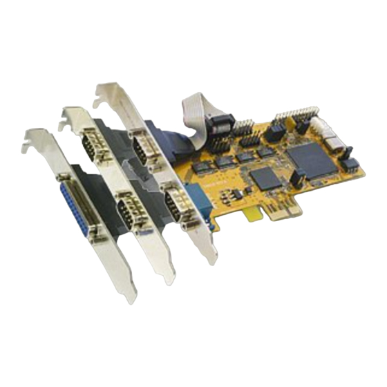
AUFBAU :
S1- Interne
JP3 Power auf 9 Pin Stecker
S4
Serielle
Ein / Aus
Anschlüsse
S2
9 Pin Stecker
Seriell Anschluss
S4
9 Pin Stecker
Seriell Anschluss
P1
25 Pin Buchse
Parallel Anschluss
S3
9 Pin Stecker
Seriell Anschluss
S1
9 Pin Stecker
JP2 UART Mode Einstellung
Seriell Anschluss
(Nur für Testzwecke im Werk)
BESCHREIBUNG & TECHNISCHE DATEN :
Die EX-44095 ist eine PCI-Express Multi I/O Karte mit einem Parallel Centronics EPP/
ECP Port und 4 seriellen FIFO 16C95x Ports, für den Anschluss von High-Speed seriel-
len RS-232 Peripherie Geräten (z.B. Terminal, Modem, Plotter usw.). Der serielle PCI-
Express Bus unterstützt dabei optimal die Leistung des schnellen 16C95x Chipsets mit
128byte FIFO Cache. Die EX-44095 gewährleistet so eine sichere Datenübertragung
und exzellente Performance von bis zu 921KBaud/s für jedes angeschlossene Gerät!
Sie unterstützt alle PCI-Express Slots von x1 bis x16. Es ist nicht möglich die I/O Ad-
ressen und Interrupts manuell einzustellen, da die Einstellungen der Karte vom System
(BIOS) und beim Installieren des Betriebssystems automatisch vorgenommen werden.
Mit dem Jumper JP1 können Sie vom Standard Quarz (1.843MHz) auf den schnellen
(14.7456MHz) Quarz umschalten. Beachten Sie bitte falls Sie mit dem schnellen Quarz
arbeiten, dass die Peripheriegeräte dies auch unterstützen. Im Gerätemanager muss
ausserdem die richtige Teilung (Divisor) & Geschwindigkeit manuell eingestellt werden.
Kompatibilität:
PCI Express x1 bis x16
Betriebs Systeme:
WIN 9.x/ME/NT 4.0/2000/XP/Server 2003/Vista/(Linux vom OS)
Anschlüsse:
4 x 9 Pin Sub-D Stecker, 1x 25Pin parallel Buchse
Lieferumfang:
EX-44095, CD, Anleitung, 2x9 Pin Kabel, 1x25 Pin Kabel
CE
Zertifikate:
/ FCC / RoHS / WEEE
JUMPER EINSTELLUNG & ANSCHLÜSSE:
JP1:
Mit dem Jumper JP1 können sie zwischen zwei Clock Geschwindigkei-
ten wählen für Kompatibilität oder höhere Baudraten.
LOW
= Die Clock ist auf 1.8432Mhz eingestellt für eine maximale
HI LOW
HI
= Die Clock ist auf 14.7456Mhz eingestellt für die maximale
Bemerkung: Bei der Einstellung HI müssen sie im Gerätemanager von
Windows bei den COM Port Einstellungen den Wert des Quarz automa-
tisch suchen und einstellen!
JP2:
Die Jumper auf JP2 bitte nicht verändern. Sie sind nur für Testzwecke
im Werk!
M2
M2
= Jumper gesetzt
M1
M1
= Jumper gesetzt
M0
M0
= Jumper nicht gesetzt
J7
Interner Parallel Port
für 25 Pin Kabel
J8
Anschluss für den
Power vom Netzteil
JP1 Umschalter
(für Datentransfer
über 115.2KBaud)
JP4 Jumper für die Strom-
quelle (Netzteil
oder PCI-Express Bus)
DE97424562 / WHQL
Baudrate von 115.2KBaud. (Werkseinstellung). Diese
Einstellung ist für die meisten Anwendungen optimal.
Baudrate von 921.6KBaud.
1

Verwandte Anleitungen für Exsys EX-44095


Inhaltszusammenfassung für Exsys EX-44095
- Seite 1 Signal Signal Die EX-44095 ist eine PCI-Express Multi I/O Karte mit einem Parallel Centronics EPP/ in the specified directory. Follow the hardware assistant and finish the installation. If ECP Port und 4 seriellen FIFO 16C95x Ports, für den Anschluss von High-Speed seriel-...
- Seite 2 Signal Signal The EX-44095 is a plug & play high-speed serial RS-232 expansion card for the PCI angegebenen Verzeichnis. Folgen sie den Anweisungen des Hardwareassistenten und Express Bus. The EX-44095 provides four 9 pin high speed RS-232 serial ports and...