Exsys EX-44098 Bedienungsanleitung
EX
EX-
EX
-
-
44098
44098
44098
JUMPER SETTING & CONNECTORS:
DB9M:
Serial 9 Pin male connector:
Pin
Signal
Pin
1
CDC
4
2
RXD
5
3
TXD
6
DB62F:
Serial 62 Pin female connector :
Pin
Signal
Pin
1
TXD 1
22
2
DTR 1
23
3
RXD 2
24
4
DSR 2
25
5
DCD 2
26
6
TXD 3
27
7
DTR 3
28
8
RXD 4
29
9
DSR 4
30
10
DCD 4
31
11
RXD 5
32
12
DSR 5
33
13
DCD 5
34
14
TXD 6
35
15
DTR 6
36
16
RXD 7
37
17
DSR 7
38
18
DCD 7
39
19
RXD 8
40
20
DSR 8
41
21
DCD 8
42
HARDWARE INSTALLATION :
If you are ready with the jumper settings, please proceed with the following installation
instructions. Because the designs of computers are different, only general installation
instructions are given. Please refer your computer's reference manual whenever in doubt.
1. Turn off the power to your computer and any other connected peripherals.
2. Remove the mounting screws located at the rear and/or sides panels of your Com-
puter and gently slide the cover off.
3. Locate an available expansion slot and remove its covers from the rear panel of your
computer. Make sure it is the right expansion slot for the card (see card description)
4. Align the card with the expansion slot, and then gently but firmly, insert the card.
Make sure the card is seated and oriented correctly. Never insert the card by force!
5. Then connect the card with a screw to the rear panel of the computer case.
6. Gently replace your computer's cover and the mounting screws.
5
English
English
English
EX
EX-
EX
-
-
44098
44098
44098
DRIVER INSTALLATION :
Windows 9x/ME/2000/XP & Vista:
After starting Windows it recognizes a new "PCI Controller" and opens the hardware
Signal
Pin
Signal
assistant. Please choose manual installation and put the driver CD into your CD-Rom
drive. Now enter the Path "D:\IO\OXFORD\" and then the directory of your operating
DTR
7
RTS
system "95_98_ME" "2000" "XP32" "XP64" "Vista32" or "Vista64" into the box for
GND
8
CTS
the Path/Source and click at >next/continue<. Now Windows searches for the drivers
DSR
9
RI
in the specified directory. Follow the hardware assistant and finish the installation. If
Windows recognizes other new devices repeat the above described steps. Attention!
Restart Windows in any case after installing the drivers.
CHECK THE INSTALLED DRIVER:
Signal
Pin
Signal
Click at Start<>Run< then enter "compmgmt.msc" and click at >OK<. In the windows
RXD 1
43
CTS 1
that opens select >Device Manager<. Under „Ports (COM and LPT)" you should find
DSR 1
44
RTS 1
a new „PCI Port" as sample (LPT2) or (Com3). If you see this or similar entries the
DCD 1
45
GND
card is installed correctly.
TXD 2
46
CTS 2
CHANGE PORT NUMBER:
DTR 2
47
RTS 2
If you like to change the port number for example COM 3 to COM5, open the >Device
RXD 3
48
CTS 3
Manager< click at >COM3<, >Settings< and then >Advance<. There you can change
DSR 3
49
RTS 3
between COM 3 till 256. The LPT Ports can be changed in the same way!
DCD 3
50
GND
TXD 4
51
CTS 4
Windows Server 2000/2003:
DTR 4
52
RTS 4
After starting Windows it recognizes a new "PCI Controller" and opens the hardware
assistant. Please choose manual installation and put the driver CD into your CD-Rom
GND
53
CTS 5
drive. Now enter the Path "D:\IO\OXFORD\" and then the directory of your operating
TXD 5
54
RTS 5
system for Server 2000: "2000" and for Server 2003: "XP32" or "XP64" into the box
DTR 5
55
GND
for the Path/Source and click at >next/continue<. Now Windows searches for the
drivers in the specified directory. Follow the hardware assistant and finish the installa-
RXD 6
56
CTS 6
tion. If Windows recognizes other new devices repeat the above described steps.
DSR 6
57
RTS 6
Attention! Restart Windows in any case after installing the drivers.
DCD 6
58
GND
CHECK THE INSTALLED DRIVER:
TXD 7
59
CTS 7
Click at Start<>Run< then enter "compmgmt.msc" and click at >OK<. In the windows
DTR 7
60
RTS 7
that opens select >Device Manager<. Under „Ports (COM and LPT)" you should find
GND
61
CTS 8
a new „PCI Port" as sample (LPT2) or (Com3). If you see this or similar entries the
card is installed correctly.
TXD 8
62
RTS 8
DTR 8
CHANGE PORT NUMBER:
If you like to change the port number for example COM 3 to COM5, open the >Device
Manager< click at >COM3<, >Settings< and then >Advance<. There you can change
between COM 3 till 256. The LPT Ports can be changed in the same way!
Windows NT 4.0:
Start Windows NT and insert the driver CD into your CD-ROM drive (for example D:).
Click at >Start< >Run< and enter „D:\IO\OXFORD\NT4\Install_Serial.exe" then click
>OK<. Windows NT will now start the setup program and install the driver. Please
Restart Windows NT after installing the drivers.
CHECK THE INSTALLED DRIVER:
Click at >Start< >Programs< >Administrative Tools[Common]< >Windows NT-
Diagnostics< then click at >Resource< >IRQ<. Here you should find the entry „09
oxser 0
PCI". Then click at >I/O-Port< here you should see the entries „D400-D407
oxser
0
for the ports. The I/O addresses can change depends which system and card is in-
stalled. If you see these or similar entry's the card is installed correctly.
LINUX:
There are no drivers available for Linux, but the card is supported by the most versions
of Linux. Because each individual distribution and kernel version of Linux is different,
sadly we cant provide a installation instruction. Please refer to the installation manual
for standard IO ports from your Linux version! In some newer versions the card will
even be installed automatically after starting Linux.
PCI" „D800-D802
oxser
0
PCI" and „DC00-DC1F oxser 0 PCI"
6
English
English
English
Bedienungsanleitung
Bedienungsanleitung
Vers. 2.0 / 17.04.07
AUFBAU :
JP1 Jumper für drehen
JP3 Nicht verändern !!!
der Ports S1-S8
Seriell Chip 16C95x
mit 128-Byte buffer
S1- 62 Pin Buchse
S8
für Octopuskabel
mit 8 x 9 pin
Seriell Anschluß
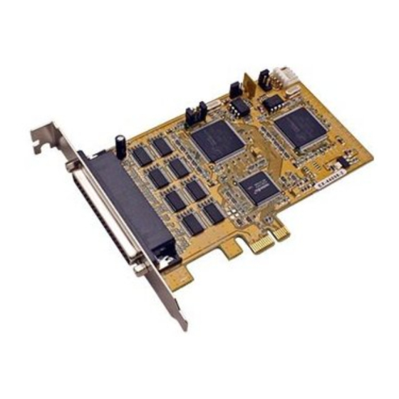
BESCHREIBUNG & TECHNISCHE DATEN :
Die EX-44098 ist eine PCI-Express serielle RS-232 Karte mit acht seriellen FIFO
16C95x Ports, für den Anschluss von High-Speed seriellen RS-232 Peripherie Geräten
(z.B. Terminal, Modem, Plotter usw.). Der serielle PCI-Express Bus unterstützt dabei
optimal die Leistung des schnellen 16C95x Chipsets mit 128byte FIFO Cache. Die EX-
44098 gewährleistet so eine sichere Datenübertragung und exzellente Performance
von bis zu 921Kbaud/s für jedes angeschlossene Gerät! Sie unterstützt alle PCI-
Express Slots von x1 bis x16. Es ist nicht möglich die I/O Adressen und Interrupts
manuell einzustellen, da die Einstellungen der Karte vom System (BIOS) und beim
Installieren des Betriebssystems automatisch vorgenommen werden. Mit dem Jumper
JP2 können Sie vom Standard Quarz (1.843MHz) auf den schnellen (14.7456MHz)
Quarz umschalten. Beachten Sie bitte falls Sie mit dem schnellen Quarz arbeiten, dass
die Peripheriegeräte dies auch unterstützen. Im Geräte Manager muss ausserdem die
richtige Teilung (Divisor) und Geschwindigkeit manuell eingestellt werden.
Kompatibilität:
PCI Express x1 bis x16
Betriebs Systeme:
WIN 9x/ME/NT 4.0/2000/XP/Server 2003/Vista(Linux vom OS)
Anschlüsse:
8 x 9 Pin Seriell D-SUB Stecker
Lieferumfang:
EX-44098, Treiber CD, Deutsche Anleitung, 8x9 Pin Kabel
Zertifikate:
CE
/ FCC / RoHS / WEEE
JUMPER EINSTELLUNG & ANSCHLÜSSE:
JP1:
A0 & B1 = Com Ports Normal S1-S8 (STANDARD)
A0
A1
A1 & B0 = Com Ports gedreht S1<>S5, S2<>S6, S3<>S7, S4<>S8
B0
B1
JP2:
1
2
HI
1 & 2 (HI) = 14.7456MHz (über 115KBaud)
3
4
LO
3 & 4 (LO) = 1.843MHz (STANDARD)
JP3:
GND (Masse) = Achtung! Jumper nicht verändern! (STANDARD)
GND | PWR
PWR (POWER) = Achtung! Jumper nicht auf diese Einstellung
setzen! Karte, PC und Endgeräte könnten beschädigt werden!
JP4:
(Nur in Verbindung mit speziellem Kabel & JP3 auf PWR!!!)
AUX5V
AUX12V
PCI12V
AUX 5V = Strom auf PIN58 mit 5Volt vom PC-Netzteil (STANDARD)
AUX 12V = Strom auf PIN58 mit 12Volt vom PC-Netzteil
PCI 12V = Strom auf PIN58 mit 12Volt vom Mainboard
J3:
1 +5V
2 GND
Für Strom vom Netzteil muss J3 mit PC Netzteil verbunden werden!
3 GND
4 +12V
JP4 Stromquellen Einstellung
(Nur für Testzwecke)
J3
Stromanschluss
für PC Netzteil
Y1 14.7456MHz quartz
(Für Datentransfer
über 115KBaud)
JP2 Jumper für Quarz
Y2 1.843MHz Quarz
Seriell Chip 16C95x
(Standard)
mit 128-Byte buffer
DE97424562 / WHQL
1

Verwandte Anleitungen für Exsys EX-44098


Inhaltszusammenfassung für Exsys EX-44098
- Seite 1 RTS 4 After starting Windows it recognizes a new “PCI Controller“ and opens the hardware Die EX-44098 ist eine PCI-Express serielle RS-232 Karte mit acht seriellen FIFO assistant. Please choose manual installation and put the driver CD into your CD-Rom...
- Seite 2 CTS 5 Windows erkennt beim Start einen neuen “PCI Controller“ und öffnet automatisch den The EX-44098 is a plug & play high-speed serial RS-232 expansion card for the PCI Windows Hardwareassistenten. Wählen sie die manuelle Installation aus und legen Sie Express Bus.