EuroLite LED KLS-200 Bedienungsanleitung
Rgb dmx licht set

Verwandte Anleitungen für EuroLite LED KLS-200


Inhaltszusammenfassung für EuroLite LED KLS-200
- Seite 1 BEDIENUNGSANLEITUNG USER MANUAL LED KLS-200 RGB DMX LIGHT SET Für weiteren Gebrauch aufbewahren! © Copyright Keep this manual for future needs! Nachdruck verboten! Reproduction prohibited!
-
Seite 2: Inhaltsverzeichnis
Inhaltsverzeichnis 1. EINFÜHRUNG ................................4 2. SICHERHEITSHINWEISE .............................. 4 3. BESTIMMUNGSGEMÄSSE VERWENDUNG ........................ 6 4. GERÄTEBESCHREIBUNG ............................7 4.1 Features ..................................7 4.2 Bedienelemente und Anschlüsse ..........................8 4. INSTALLATION ................................9 4.1 Montage auf einem Stativ............................9 4.2 Befestigung an einer Traverse ..........................9 4.3 Scheinwerfer umsetzen............................. - Seite 3 Diese Bedienungsanleitung gilt für die Artikelnummern / This user manual is valid for the article numbers: 42109700 Das neueste Update dieser Bedienungsanleitung finden Sie im Internet unter: You can find the latest update of this user manual in the Internet under: www.eurolite.de 3/31 00054242.DOC, Version 1.2...
-
Seite 4: Einführung
- sich die letzte Version der Anleitung im Internet herunter laden 1. EINFÜHRUNG Wir freuen uns, dass Sie sich für das EUROLITE Kompakt-Lichtset LED KLS-200 RGB DMX entschieden haben. Wenn Sie nachfolgende Hinweise beachten, sind wir sicher, dass Sie lange Zeit Freude an Ihrem Kauf haben werden. - Seite 5 Bitte überprüfen Sie vor der ersten Inbetriebnahme, ob kein offensichtlicher Transportschaden vorliegt. Sollten Sie Schäden an der Netzleitung oder am Gehäuse entdecken, nehmen Sie das Gerät nicht in Betrieb und setzen sich bitte mit Ihrem Fachhändler in Verbindung. Der Aufbau entspricht der Schutzklasse I. Der Netzstecker darf nur an eine Schutzkontakt-Steckdose angeschlossen werden, deren Spannung und Frequenz mit dem Typenschild des Gerätes genau übereinstimmt.
-
Seite 6: Bestimmungsgemässe Verwendung
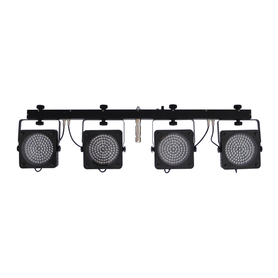
3. BESTIMMUNGSGEMÄSSE VERWENDUNG Das Kompakt-Lichtset LED KLS-200 RGB DMX besteht aus vier superflachen LED-Scheinwerfern und der Steuereinheit. Die Lieferung erfolgt vormontiert in einer praktischen Transporttasche. Das Set kann auf ein Leuchten-Stativ aufgesetzt oder an einer Traverse befestigt werden. Dank der integrierten Steuereinheit mit LED-Anzeige lässt sich das Lichtset allein im musikgesteuerten Modus oder im Automatikbetrieb mit prozessorgesteuerten Farbwechseln betreiben. -
Seite 7: Gerätebeschreibung
Soll das Gerät transportiert werden, verwenden Sie bitte die Originalverpackung, um Transportschäden zu vermeiden. Achten Sie bitte unbedingt darauf, dass das Gerät im Lieferzustand verpackt wird. Beachten Sie bitte, dass eigenmächtige Veränderungen an dem Gerät aus Sicherheitsgründen verboten sind. Der Serienbarcode darf niemals vom Gerät entfernt werden, da ansonsten der Garantieanspruch erlischt. Wird das Gerät anders verwendet als in dieser Bedienungsanleitung beschrieben, kann dies zu Schäden am Produkt führen und der Garantieanspruch erlischt. -
Seite 8: Bedienelemente Und Anschlüsse
4.2 Bedienelemente und Anschlüsse Mikrofon zur Musiksteuerung Buchse DMX OUT DMX-Signalausgang (3-pol. XLR) zum Anschluss an den DMX-Eingang eines weiteren Lichteffektgeräts Empfindlichkeitsregler für das Mikrofon Netzanschluss mit Sicherungshalter Anschluss für den Fußschalter FP-1 • Stecken Sie hier die Netzleitung ein. •... -
Seite 9: Installation
4. INSTALLATION 4.1 Montage auf einem Stativ Für den mobilen Einsatz setzen Sie das Lichtset auf ein Leuchten-Stativ auf. Passende Artikel finden Sie im Kapitel Zubehör. 1. Lösen Sie zunächst am Stativ die Feststellschrauben der Stellfüße. Ziehen Sie die Stellfüße aus, bis die Querstreben in einem 90°-Winkel zu den Stellfüßen stehen. - Seite 10 LEBENSGEFAHR! Bei der Installation sind insbesondere die Bestimmungen der BGV C1 (vormals VBG 70) und DIN 15560-27 zu beachten! Die Installation darf nur vom autorisierten Fachhan- del ausgeführt werden! Während des Auf-, Um- und Abbaus ist der unnötige Aufenthalt im Bereich von Bewegungsflächen, auf Beleuchterbrücken, unter hochgelegenen Arbeitsplätzen sowie an sonstigen Gefahrbereichen verboten.
-
Seite 11: Anschlüsse Herstellen
5. ANSCHLÜSSE HERSTELLEN 5.1 Anschluss ans Netz 1. Schließen Sie das Gerät über das Netzkabel ans Netz an (230 V AC, 50 Hz ~). Die Belegung der Anschlussleitungen ist wie folgt: Leitung International Braun Außenleiter Blau Neutralleiter Gelb/Grün Schutzleiter Hinweis: Der Schutzleiter muss unbedingt angeschlossen werden! Wenn das Gerät direkt an das örtliche Stromnetz angeschlossen wird, muss eine Trennvorrichtung mit mindestens 3 mm Kontaktöffnung an jedem Pol in die festverlegte elektrische Installation eingebaut werden. -
Seite 12: Zusammenschalten Mehrerer Lichtsets (Master/Slave-Betrieb)
5.3 Zusammenschalten mehrerer Lichtsets (Master/Slave-Betrieb) Es lassen sich mehrere Lichtsets zusammenschalten. Das Hauptgerät (Master) kann dann alle Nebengeräte (Slave) synchron steuern. 1. Verbinden Sie den Anschluss DMX OUT des Hauptgeräts über ein 3-poliges XLR-Kabel mit dem Anschluss DMX IN des ersten Nebengeräts. 2. -
Seite 13: Master/Slave-Betrieb Mit Mehreren Lichtsets
6.1.3 Master/Slave-Betrieb mit mehreren Lichtsets 1. Sind mehrere Lichtsets zusammengeschaltet ( 5.3), lassen sich mit dem Hauptgerät (Master) alle Nebengeräte (Slave) synchron steuern. Wählen Sie dazu am Hauptgerät die gewünschte Betriebsart (Musiksteuerung oder Automatikbetrieb) und stellen Sie jedes der Nebengeräte auf die gleiche DMX- Startadresse ein: 6.3.1). -
Seite 14: Dmx-Protokoll
6.3.2 DMX-Protokoll Kanal 1 – Voreingestellte Programme, Automatikbetrieb, Musiksteuerung DMX-Wert Funktion 000 – 009 010 – 029 Programm 1 030 – 049 Programm 2 050 – 069 Programm 3 070 – 089 Programm 4 090 – 109 Programm 5 110 – 129 Programm 6 130 –... -
Seite 15: Betrieb Mit Dem Dmx Led Operator 4
Kanal 9 – Spot 2: Helligkeit Blau DMX-Wert Funktion 000 – 255 Dimmen von 0 – 100% Kanal 10 – Spot 3: Helligkeit Rot DMX-Wert Funktion 000 – 255 Dimmen von 0 – 100% Kanal 11 – Spot 3: Helligkeit Grün DMX-Wert Funktion 000 –... -
Seite 16: Reinigung Und Wartung
7. REINIGUNG UND WARTUNG Der Unternehmer hat dafür zu sorgen, dass sicherheitstechnische und maschinentechnische Einrichtungen mindestens alle vier Jahre durch einen Sachverständigen im Umfang der Abnahmeprüfung geprüft werden. Der Unternehmer hat dafür zu sorgen, dass sicherheitstechnische und maschinentechnische Einrichtungen mindestens einmal jährlich durch einen Sachkundigen geprüft werden. Dabei muss unter anderem auf folgende Punkte besonders geachtet werden: 1) Alle Schrauben, mit denen das Gerät oder Geräteteile montiert sind, müssen fest sitzen und dürfen nicht korrodiert sein. -
Seite 17: Technische Daten
EUROLITE FP-1 Fußschalter Best.-Nr. 42109710 EUROLITE STV-40S Stativ, Stahl Best.-Nr. 59006996 EUROLITE STV-40A Stativ, Alu Best.-Nr. 59007001 EUROLITE STV-40-WOT Stativ,Alu ohne T-bar Best.-Nr. 59007002 EUROLITE STV-40S-WOT Stativ,o.T-bar Stahl Best.-Nr. 59007004 EUROLITE DMX LED Operator 4 Best.-Nr. 70064504 Bitte beachten Sie: Technische Änderungen ohne vorherige Ankündigung und Irrtum vorbehalten.