Herunterladen Inhalt Inhalt Diese Seite drucken
Videotec HOV32K1A018 Bedienungsanleitung

Videotec HOV32K1A018 Bedienungsanleitung

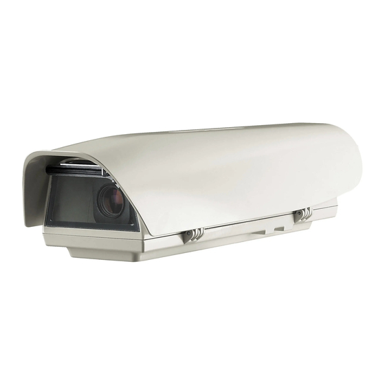
Aluminiumgehaeuse mit seitenoeffnung
Inhaltsverzeichnis

Werbung

Verfügbare Sprachen
  • DE

Verfügbare Sprachen

  • DEUTSCH, seite 46
EN
English - Instructions manual
Italiano - Manuale di istruzioni
IT
Français - Manuel d'instructions
FR
Deutsch - Bedienungslanleitung
DE
Русский - Руководство по эксплуатации
RU
Side opening aluminium camera housing
HOV

Werbung

Inhaltsverzeichnis
loading

Inhaltszusammenfassung für Videotec HOV32K1A018

  • Seite 1 Side opening aluminium camera housing English - Instructions manual Italiano - Manuale di istruzioni Français - Manuel d’instructions Deutsch - Bedienungslanleitung Русский - Руководство по эксплуатации...
  • Seite 3 Side opening aluminium camera housing English - Instructions manual...
  • Seite 4: Inhaltsverzeichnis

    Contents ENGLISH 1 About this manual ......................3 1.1 Typographical conventions ..........................3 2 Notes on copyright and information on trademarks ..........3 3 Safety rules........................3 4 Identification ........................4 4.1 Product description and type designation..................... 4 4.2 Product markings ..............................4 5 Preparing the product for use ..................
  • Seite 5: About This Manual

    1 About this manual 3 Safety rules Before installing and using this unit, please read this CAUTION! The device must be installed manual carefully. Be sure to keep it handy for later only and exclusively by qualified technical reference. personnel. 1.1 Typographical conventions CAUTION! The electrical system to which the unit is connected must be equipped...
  • Seite 6: Identification

    • This device was designed to be permanently • A disconnecting device, readily and easily installed on a building or on a suitable structure. accessible, must be incorporated in the electrical The device must be installed permanently before system of the building for rapid intervention. any operation.
  • Seite 7: Preparing The Product For Use

    5 Preparing the product for 5.5 Safely disposing of packaging material The packaging material can all be recycled. The Any change that is not expressly approved installer technician will be responsible for separating by the manufacturer will invalidate the the material for disposal, and in any case for guarantee.
  • Seite 8: Installation

    6 Installation 6.2 How to install the camera 6.1 How to open the housing Power supply can be provided by the board supplied with the product. Make sure the Loosen the 2 screws on the side, turn the cover and voltage values are appropriate.
  • Seite 9: Board Description

    6.3 Board description 6.4 Connection of the power supply line Connect the safety earth to the relative terminal of the J1 connector. Earth cable should be about 10mm longer than the other two, so that it will not be The board may appear different to that disconnected accidentally if pulled.
  • Seite 10: Installation Of The Version With Double Filter For Air Renewal

    6.5 Installation of the version 6.6 Installation of the version with double filter for air renewal with wiper Open the housing as described (6.1 How to open the During installation pay attention to the housing, page 6). orientation of the air inlet filter fins. Identify the terminal on the wiper board.
  • Seite 11: Accessories

    7 Accessories 7.2 Camera power supply 7.2.1 Camera power supply installation For further details on configuration and use, refer to the relative manual. Not usable in housings with wiper device installed. 7.1 Heater Pay attention to the voltage value used 7.1.1 Heater installation when the circuit is powered.
  • Seite 12: Blower

    7.3 Blower Open the housing as described (6.1 How to open the housing, page 6). 7.3.1 Blower installation Fix the support bracket (02) using the screw (01). Place the power supply (03) on the support bracket. Not usable in versions with double filter for Secure it all with the screws (04) and the corner fixing air renewal and wiper.
  • Seite 13: Instructions For Normal Operation

    8 Instructions for normal 10 Disposal of waste operation materials Do not use the wiper when the outside This symbol mark and recycle system temperature is below 0°C or in case of ice. are applied only to EU countries and not applied to the countries in the other area of 9 Maintaining and cleaning the world.
  • Seite 14: Technical Data

    • From 100Vac up to 240Vac, 40mA max, UL certification: cULus Listed, TYPE 4X (except for 50/60Hz (with wide-range power supply) versions with double filter for the air exchange, HOV32K1A018, HOV32K2A016, HOV32K2A017, HOV32K2A147, and the version with wiper 230Vac, HOV32K1A100) EAC certification...
  • Seite 15: Technical Drawings

    12 Technical drawings The dimensions of the drawings are in millimetres. USABLE USABLE AREA AREA A - A B - B R100 Fig. 14 HOV. MNVCHOV32_1511_EN...
  • Seite 16 Email: info@videotec.com Tel. +33 1 60491816 - Fax +33 1 69284736 Email: info.fr@videotec.com Asia Pacific Videotec (HK) Ltd Americas Videotec Security, Inc. Flat 8, 19/F. On Dak Industrial Building, No. 2-6 Wah Sing Street Gateway Industrial Park, 35 Gateway Drive, Suite 100 Kwai Chung, New Territories - Hong Kong Plattsburgh, NY 12901 - U.S.A.
  • Seite 17: Custodia Per Telecamera In Alluminio Ad Apertura Laterale

    Custodia per telecamera in alluminio ad apertura laterale Italiano - Manuale di istruzioni...
  • Seite 18 Sommario ITALIANO 1 Informazioni sul presente manuale ................3 1.1 Convenzioni tipografiche ............................. 3 2 Note sul copyright e informazioni sui marchi commerciali ........3 3 Norme di sicurezza ......................3 4 Identificazione ....................... 4 4.1 Descrizione e designazione del prodotto ....................... 4 4.2 Marcatura del prodotto ............................
  • Seite 19: Informazioni Sul Presente Manuale

    1 Informazioni sul presente 3 Norme di sicurezza manuale ATTENZIONE! L'installazione e la manutenzione del dispositivo deve Prima di installare e utilizzare questa unità, leggere essere eseguita solo da personale tecnico attentamente questo manuale. Conservare questo qualificato. manuale a portata di mano come riferimento futuro. 1.1 Convenzioni tipografiche ATTENZIONE! L’impianto elettrico al quale è...
  • Seite 20: Identificazione

    • Questo dispositivo è stato progettato per essere • Un dispositivo di scollegamento, prontamente e installato in maniera permanente su un edificio facilmente accessibile, deve essere incorporato o su una struttura adeguata. Il dispositivo deve nell'impianto elettrico dell'edificio per un essere installato in maniera permanente prima di intervento rapido.
  • Seite 21: Preparazione Del Prodotto Per L'utilizzo

    5 Preparazione del prodotto 5.5 Smaltimento in sicurezza dei materiali di imballaggio per l'utilizzo I materiali d'imballo sono costituiti interamente da Qualsiasi cambiamento non espressamente materiale riciclabile. Sarà cura del tecnico installatore approvato dal costruttore fa decadere la smaltirli secondo le modalità di raccolta differenziata garanzia.
  • Seite 22: Installazione

    6 Installazione 6.2 Installazione della telecamera 6.1 Apertura della custodia L'alimentazione può essere fornita dalla scheda in dotazione al prodotto. Accertarsi Svitare le 2 viti poste sul fianco, far ruotare tettuccio che i valori di tensione siano adeguati. e corpo superiore attorno all’asse delle cerniere di Aprire la custodia come descritto (6.1 Apertura della apertura.
  • Seite 23: Descrizione Della Scheda

    6.3 Descrizione della scheda 6.4 Collegamento della linea di alimentazione Collegare la terra di sicurezza al relativo morsetto del connettore J1. Il cavo di terra deve essere più lungo degli altri due di circa 10mm per prevenirne L'aspetto della scheda potrebbe differire da il distacco accidentale a causa dello quello illlustrato.
  • Seite 24: Installazione Della Versione Con Doppio Filtro Per Ricambio Dell'aria

    6.5 Installazione della versione 6.6 Installazione della versione con doppio filtro per ricambio con tergicristallo dell'aria Aprire la custodia come descritto (6.1 Apertura della custodia, pagina 6). Durante l'installazione prestare attenzione Individuare il morsetto della scheda tergicristallo. all'orientamento delle alette del filtro di ingresso dell'aria.
  • Seite 25: Accessori

    7 Accessori 7.2 Alimentatore per telecamera 7.2.1 Installazione dell’alimentatore per Per ulteriori dettagli sulla configurazione telecamera e l’utilizzo fare riferimento al manuale del relativo accessorio. Non utilizzabile nelle custodie munite di sistema tergicristallo. 7.1 Riscaldamento Prestare attenzione al valore di tensione 7.1.1 Installazione del riscaldamento utilizzata quando si alimenta il circuito.
  • Seite 26: Ventilatore

    7.3 Ventilatore Aprire la custodia come descritto (6.1 Apertura della custodia, pagina 6). 7.3.1 Installazione del ventilatore Utilizzando la vite (01) fissare la staffa di appoggio (02). Posizionare l'alimentatore (03) sulla staffa di Non utilizzabile nelle versioni con doppio appoggio. Fissare il tutto con le viti (04) e la staffa di filtro per il ricambio dell'aria e tergicristallo.
  • Seite 27: Istruzioni Di Funzionamento Ordinario

    8 Istruzioni di 10 Smaltimento dei rifiuti funzionamento ordinario Questo simbolo e il sistema di riciclaggio sono validi solo nei paesi dell'EU e non Non utilizzare il tergicristallo quando la trovano applicazione in altri paesi del temperatura esterna è inferiore a 0°C o in mondo.
  • Seite 28: Dati Tecnici

    Certificazione UL: cULus Listed, TYPE 4X (ad • Da 100Vac fino a 240Vac, 40mA max, 50/60Hz (con eccezione delle versioni con doppio filtro per il alimentatore wide-range) ricambio dell'aria, HOV32K1A018, HOV32K2A016, HOV32K2A017, HOV32K2A147, e della versione con tergicristallo in 230Vac, HOV32K1A100) Certificazione EAC...
  • Seite 29: Disegni Tecnici

    12 Disegni tecnici Le dimensioni dei disegni sono espresse in millimetri. AREA AREA UTILE UTILE A - A B - B R100 Fig. 14 HOV. MNVCHOV32_1511_IT...
  • Seite 30 Email: info@videotec.com Tel. +33 1 60491816 - Fax +33 1 69284736 Email: info.fr@videotec.com Asia Pacific Videotec (HK) Ltd Americas Videotec Security, Inc. Flat 8, 19/F. On Dak Industrial Building, No. 2-6 Wah Sing Street Gateway Industrial Park, 35 Gateway Drive, Suite 100 Kwai Chung, New Territories - Hong Kong Plattsburgh, NY 12901 - U.S.A.
  • Seite 31 Caisson pour caméra en aluminium à ouverture latérale Français - Manuel d’instructions...
  • Seite 32 Sommaire FRANÇAIS 1 À propos de ce mode d’emploi ..................3 1.1 Conventions typographiques ..........................3 2 Notes sur le copyright et informations sur les marques de commerce ..... 3 3 Normes de securité ......................3 4 Identification ........................4 4.1 Description et désignation du produit ......................
  • Seite 33: Propos De Ce Mode D'emploi

    1 À propos de ce mode 3 Normes de securité d’emploi ATTENTION! L’installation et l’entretien du dispositif doivent être exclusivement Avant d’installer et d’utiliser cet appareil, veuillez être effectués par un personnel technique lire attentivement ce mode d’emploi. Conservez-le à qualifié.
  • Seite 34: Identification

    • Cette appareil est conçu pour une installation • Un dispositif de déconnexion, rapide et facile permanente sur un bâtiment ou une structure d'accès, doit être incorporé dans le circuit adéquate. L'appareil doit être installé d'une façon électrique du bâtiment pour une intervention permanente avant d'effectuer toute opération.
  • Seite 35: Préparation Du Produit En Vue De L'utilisation

    5 Préparation du produit en 5.5 Élimination sans danger des matériaux d’emballage vue de l’utilisation Le matériel d’emballage est entièrement composé Toute modification non approuvée de matériaux recyclables. Le technicien chargé de expressément par le fabricant entraînera l’installation est tenu de l’éliminer conformément aux l’annulation de la garantie.
  • Seite 36: Installation

    6 Installation 6.2 Installation de la caméra 6.1 Ouverture du caisson L'alimentation peut être dotée de la carte fournie avec le produit fournie. Dévisser les 2 vis placées sur le côté, faire tourner le S'assurer que les valeurs de tension soient toit pare-soleil et le corps supérieur autour de l’axe appropriées.
  • Seite 37: Description De La Carte

    6.3 Description de la carte 6.4 Connexion de la ligne d'alimentation Faire le branchement de sécurité à la terre de la borne correspondante du connecteur Le câble de terre doit être plus long des deux autres d'environ 10mm pour éviter tout détachement accidentel.
  • Seite 38: Installation De La Version Avec Double Filtre Pour Le Changement D'air

    6.5 Installation de la version avec 6.6 Installation de la version avec double filtre pour le changement essuie-glace d'air Ouvrir le caisson comme décrit (6.1 Ouverture du caisson, page 6). Durant l'installation prêter l'installation à Identifier la borne de la carte de l'essui-glace. l'orientation des ailettes du filtre d'entrée de l'air.
  • Seite 39: Accessoires

    7 Accessoires 7.2 Alimentation pour caméra 7.2.1 Installation de l’alimentateur pour Pour de plus amples informations sur la caméra configuration et l'utilisation, consulter le manuel de l'accessoire correspondant. Pas utilisable pour les caissons équipés de système essuie-glace installé. 7.1 Chauffage Il faut faire attention au valeur de tension 7.1.1 Installation du chauffage utilisée en alimentant le circuit.
  • Seite 40: Ventilateur

    7.3 Ventilateur Ouvrir le caisson comme décrit (6.1 Ouverture du caisson, page 6). 7.3.1 Installation du ventilateur En utilisant la vis (01) fixer la bride de soutien (02). Positionner l'alimentateur (03) sur la bride de soutien. Pas utilisable dans les versions avec double Fixer le tout avec les vis (04) et la bride de fixation filtre pour le changement d’air et essuie- d'angle (05).
  • Seite 41: Instructions De Fonctionnement Courant

    8 Instructions de 10 Élimination des déchets fonctionnement courant Ce symbole et le système de recyclage ne sont appliqués que dans les pays UE et non Ne pas utiliser l’essuie-glace lorsque la dans les autres pays du monde. température extérieure est inférieure à 0°C Votre produit est conçu et fabriqué...
  • Seite 42: Données Techniques

    • IP44 (avec double filtre pour le renouvellement 50/60Hz (avec alimentation wide-range) de l’air) Certification UL: cULus Listed, TYPE 4X (à l'exception des versions avec double filtre pour l'échange d'air HOV32K1A018, HOV32K2A016, HOV32K2A017, HOV32K2A147 et la version avec essuie-glace 230Vac HOV32K1A100) Certification EAC MNVCHOV32_1511_FR...
  • Seite 43: Dessins Techniques

    12 Dessins techniques Les dimensions des dessins sont exprimées en millimètres. SURFACE SURFACE UTILE UTILE A - A B - B R100 Fig. 14 HOV. MNVCHOV32_1511_FR...
  • Seite 44 Email: info@videotec.com Tel. +33 1 60491816 - Fax +33 1 69284736 Email: info.fr@videotec.com Asia Pacific Videotec (HK) Ltd Americas Videotec Security, Inc. Flat 8, 19/F. On Dak Industrial Building, No. 2-6 Wah Sing Street Gateway Industrial Park, 35 Gateway Drive, Suite 100 Kwai Chung, New Territories - Hong Kong Plattsburgh, NY 12901 - U.S.A.
  • Seite 45: Aluminiumgehäuse Mit Seitenöffnung

    Aluminiumgehäuse mit Seitenöffnung Deutsch - Bedienungslanleitung...
  • Seite 46 Inhaltsverzeichnis DEUTSCH 1 Allgemeines ........................3 1.1 Schreibweisen ................................3 2 Anmerkungen zum Copyright und Informationen zu den Handelsmarken ..... 3 3 Sicherheitsnormen ......................3 4 Identifizierung ....................... 4 4.1 Beschreibung und Bezeichnung des Produktes ................... 4 4.2 Kennzeichnung des Produkts..........................4 5 Vorbereitung des Produktes auf den Gebrauch............
  • Seite 47: Allgemeines

    1 Allgemeines 3 Sicherheitsnormen Lesen Sie bitte vor dem Installieren und dem ACHTUNG! Die Installation und Wartung Verwenden dieses Gerätes die Bedienungsanleitung der Vorrichtung ist technischen Fachleuten sorgfältig durch. Bewahren Sie sie zum späteren vorbehalten. Nachschlagen auf. 1.1 Schreibweisen ACHTUNG! Die elektrische Anlage, an der die Einheit angeschlossen ist, muss mit einem automatischen zweipoligen GEFAHR!
  • Seite 48: Identifizierung

    • Die Einrichtung ist für den dauerhaften Einbau • Eine sofort und problemlos zugängliche in ein Gebäude oder eine andere geeignete Abtrennvorrichtung muss in die Elektroanlage des Struktur konzipiert. Vor jeder Operation muss die Gebäudes eingebaut werden, um einen schnellen Einrichtung dauerhaft eingebaut werden.
  • Seite 49: Vorbereitung Des Produktes Auf Den Gebrauch

    5 Vorbereitung des 5.5 Sichere Entsorgung der Verpackungsmaterialien Produktes auf den Gebrauch Die Verpackungsmaterialien sind vollständig Jede vom Hersteller nicht ausdrücklich wiederverwertbar. Es ist Sache des genehmigte Veränderung führt zum Verfall Installationstechnikers, sie getrennt, auf jeden der Gewährleistungsrechte. Fall aber nach den geltenden Vorschriften des Anwendungslandes zu entsorgen.
  • Seite 50: Installation

    6 Installation 6.2 Installation der Kamera 6.1 Öffnung des Schutzgehause Die Stromversorgung muss über die Karte erfolgen, die im Lieferumfang des Die beiden an der Flanke befindlichen Schrauben Geräts enthalten ist. Prüfen, dass die abdrehen, nun die Haube und den oberen Korpus um Spannungswerte angemessen sind.
  • Seite 51: Beschreibung Der Karte

    6.3 Beschreibung der Karte 6.4 Anschluss der Stromversorgung Die Schutzerde an Verbinder J1 mit der zugehörigen Klemme anschließen. Das Erdungskabel muss um etwa 10mm länger sein, als die anderen beiden Kabel, Die Abbildung kann von der tatsächlichen um das ungewollte Lösen durch Ziehen des Karte abweichen.
  • Seite 52: Installation Der Version Mit Doppelfilter Für Den Luftaustausch

    6.5 Installation der Version 6.6 Installation der Ausführung mit Doppelfilter für den mit Scheibenwischer Luftaustausch Das Gehäuse öffnen wie beschrieben (6.1 Öffnung des Schutzgehause, Seite 6). Während der Installation auf die Die Klemme der Wischerplatine ausfindig machen. Ausrichtung der Luftklappen am Lufteinlassfilter achten.
  • Seite 53: Zubehör

    7 Zubehör 7.2 Kameranetzteil 7.2.1 Installation des Netzteil für Für weitere Details zur Konfiguration und Kamera zum Gebrauch beachten Sie bitte das Handbuch des entsprechenden Geräts. Nicht anwendbar in Gehäusen mit installiertem Scheibenwischer. 7.1 Heizung Wenn der Schaltkreis gespeist wird, muß 7.1.1 Installation der Heizung auf Versorgungsspannungswert geachtet Das Gehäuse öffnen wie beschrieben (6.1 Öffnung...
  • Seite 54: Lüfter

    7.3 Lüfter Das Gehäuse öffnen wie beschrieben (6.1 Öffnung des Schutzgehause, Seite 6). 7.3.1 Installation des Lüfters Mit der Schraube (01) den Haltebügel (02) befestigen. Das Netzteil (03) auf den Haltebügel stellen. Alles Nicht anwendbar in den Ausführungen mit mit den Schrauben (04) und der Winkelkonsole (05) Doppelfilter und Scheibenwischer für den befestigen.
  • Seite 55: Anleitung Für Den Normalen Betrieb

    8 Anleitung für den 10 Müllentsorgungsstellen normalen Betrieb Dieses Symbol und das entsprechende Recycling-System gelten nur für EULänder Der Scheibenwischer ist bei und finden in den anderen Ländern der Aussentemperaturen unter 0°C oder bei Welt keine Anwendung. Glas nicht zu betätigen. Ihr Produkt wurde entworfen und hergestellt 9 Wartung und Reinigung aus qualitativ hochwertigen Materialien und...
  • Seite 56: Technische Daten

    UL- Zertifizierung: cULus Listed, TYPE 4X (mit • Von 100Vac bis zu 240Vac, 40mA max, Ausnahme für die Versionen mit Doppelfilter für 50/60Hz (mit Wide-range Netzteil) den Luftaustausch, HOV32K1A018, HOV32K2A016, HOV32K2A017, HOV32K2A147, und der Version mit Wischer 230Vac, HOV32K1A100) EAC-Zertifizierung...
  • Seite 57: Technische Zeichnungen

    12 Technische Zeichnungen Die Abmessungen der Zeichnungen sind in Millimeter angegeben. NUTZ- NUTZFLÄCHE FLÄCHE A - A B - B R100 Abb. 14 HOV. MNVCHOV32_1511_DE...
  • Seite 58 Email: info@videotec.com Tel. +33 1 60491816 - Fax +33 1 69284736 Email: info.fr@videotec.com Asia Pacific Videotec (HK) Ltd Americas Videotec Security, Inc. Flat 8, 19/F. On Dak Industrial Building, No. 2-6 Wah Sing Street Gateway Industrial Park, 35 Gateway Drive, Suite 100 Kwai Chung, New Territories - Hong Kong Plattsburgh, NY 12901 - U.S.A.
  • Seite 59 Откидной алюминиевый кожух камеры Русский - Руководство по эксплуатации...
  • Seite 60 Индекс РУССКИЙ 1 Информация о настоящем руководстве ................3 1.1 Типографские обозначения ............................3 2 Примечания по авторскому праву и торговым маркам ..........3 3 Правила безопасности ......................3 4 Идентификация ........................4 4.1 Описание и назначение изделия ..........................4 4.2 Маркировка изделия ..............................4 5 Подготовка изделия к использованию ................5 5.3 Распаковка...
  • Seite 61: Информация О Настоящем Руководстве

    1 Информация о настоящем 3 Правила безопасности руководстве ПРЕДУПРЕЖДЕНИЕ! Следует использовать только кронштейны или принадлежности, Перед монтажом и использованием настоящего рекомендуемые для монтажа. блока, внимательно прочитать настоящее руководство. Хранить данное руководство под рукой ПРЕДУПРЕЖДЕНИЕ! Система для будущих консультаций. электропитания, к которой подключен 1.1 Типографские...
  • Seite 62: Идентификация

    • Это устройство предназначено для постоянно • Размыкающее устройство, с быстрым и лёгким действующей установки на здании или на доступом, предназначенное для встраивания соответствующей конструкции. Устройство должно в электросистему здания и обеспечивающее быть установлено на постоянной основе перед быстрое срабатывание. выполнением...
  • Seite 63: Подготовка Изделия К Использованию

    5 Подготовка изделия к 5.5 Переработка в отходы в условиях безопасности использованию материалов упаковки Любое изменение, выполненное без Материалы упаковки полностью состоят из разрешения изготовителя, ведёт к потери рекуперируемого материала. Техник по установке гарантии. должен переработать их в отходы в соответствии с 5.3 Распаковка...
  • Seite 64: Монтаж

    6 Монтаж 6.2 Установка телекамеры 6.1 Открытие корпуса Питание может обеспечиваться платой, прилагающейся к изделию. Убедитесь в Отвинтите 2 винта, установленные на боку, адекватности значений напряжения. поверните крышку и верхний корпус вокруг оси Откройте футляр как описано (6.1 Открытие корпуса, петель...
  • Seite 65: Описание Платы

    6.3 Описание платы 6.4 Подключение к линии питания Подключите защитное заземление к соответствующей клемме разъема J1. Провод заземления должен быть длиннее двух других примерно на 10mm, с целью Вид платы может отличаться от предотвращения случайного отсоединения показанного. по причине растяжения кабеля. Плата, в...
  • Seite 66: Установка Версии С Двойным Фильтром Для Воздухообмена

    6.5 Установка версии с двойным 6.6 Установка версии со фильтром для воздухообмена стеклоочистителем Откройте футляр как описано (6.1 Открытие корпуса, Во время установки обратите внимание страница 6). на ориентировку ребер фильтра на входе воздуха. Определите клемму платы стеклоочистителя. Рис. 6 Подключите плату стеклоочистителя к сети питания, Рис.
  • Seite 67: Аксессуары

    7 Аксессуары 7.2 Блоки питания для камер 7.2.1 Установка блока питания для Для дополнительной информации телекамеры по конфигурации и использованию обращаться к руководству по эксплуатации Не используется в футлярах, оснащенных соответствующего оборудования. системой стеклоочищения. 7.1 Нагреватель Обратите внимание на значение используемого...
  • Seite 68: Вентилятор

    7.3 Вентилятор Откройте футляр как описано (6.1 Открытие корпуса, страница 6). 7.3.1 Установка вентилятора С помощью винтов (01) закрепите опорную скобу (02). Расположите блок питания (03) на опорной Не используется в версиях с двойным скобе. Прикрепите все с помощью винтов (04) и фильтром...
  • Seite 69: Инструкции По Обычному Функционированию

    8 Инструкции по обычному 10 Вывоз в отходы функционированию Этот символ и система утилизации имеют значение только в странах ЕС и не находят Не пользуйтесь стеклоочистителем, применения в других странах мира. когда внешняя температура ниже 0°C или Ваше изделие были изготовлено из материалов имеется...
  • Seite 70: Технические Параметры

    • От 100Vac до 240Vac, 40mA max, 50/60Hz (с Сертификация UL: cULus Listed, TYPE 4X (за блоком питания wide-range) исключением версий с двойным фильтром для воздухообмена и стеклоочистителем HOV32K1A018, HOV32K2A016, HOV32K2A017, HOV32K2A147, и версии со стеклоочистителем 230Vac, HOV32K1A100) Сертификат EAC...
  • Seite 71: Технические Чертежи

    12 Технические чертежи Размеры в чертежах выражены в миллиметрах. ПОЛЕЗНАЯ ПОЛЕЗНАЯ ОБЛАСТЬ ОБЛАСТЬ A - A B - B R100 Рис. 14 HOV. MNVCHOV32_1511_RU...
  • Seite 72 Email: info@videotec.com Tel. +33 1 60491816 - Fax +33 1 69284736 Email: info.fr@videotec.com Asia Pacific Videotec (HK) Ltd Americas Videotec Security, Inc. Flat 8, 19/F. On Dak Industrial Building, No. 2-6 Wah Sing Street Gateway Industrial Park, 35 Gateway Drive, Suite 100 Kwai Chung, New Territories - Hong Kong Plattsburgh, NY 12901 - U.S.A.
  • Seite 74 Email: info@videotec.com Tel. +33 1 60491816 - Fax +33 1 69284736 Email: info.fr@videotec.com Asia Pacific Videotec (HK) Ltd Americas Videotec Security, Inc. Flat 8, 19/F. On Dak Industrial Building, No. 2-6 Wah Sing Street Gateway Industrial Park, 35 Gateway Drive, Suite 100 Kwai Chung, New Territories - Hong Kong Plattsburgh, NY 12901 - U.S.A.

Inhaltsverzeichnis