Herunterladen Inhalt Inhalt Diese Seite drucken

Videotec HGV Bedienungsanleitung

Extra grosses kameragehause
Vorschau ausblenden Andere Handbücher für HGV:
Inhaltsverzeichnis

Werbung

Verfügbare Sprachen
  • DE

Verfügbare Sprachen

  • DEUTSCH, seite 52
English - Instructions manual
EN
Italiano - Manuale di istruzioni
IT
Français - Manuel d'instructions
FR
Deutsch - Bedienungslanleitung
DE
Русский - Руководство по эксплуатации
RU
Extra-large sized housing
HGV

Werbung

Inhaltsverzeichnis
loading

Inhaltszusammenfassung für Videotec HGV

  • Seite 1 Extra-large sized housing English - Instructions manual Italiano - Manuale di istruzioni Français - Manuel d’instructions Deutsch - Bedienungslanleitung Русский - Руководство по эксплуатации...
  • Seite 3 ENGLISH Extra large-sized camera housing English - Instruction manual...
  • Seite 4: Inhaltsverzeichnis

    Contents E N G L I S H 1 About this manual ......................4 1.1 Typographical conventions ..........................4 2 Notes on copyright and information on trademarks ..........4 3 Safety rules........................4 4 Identification ........................5 4.1 Product description and type designation..................... 5 4.2 Product marking ..............................
  • Seite 5 11 Technical drawings ....................14 MNVCHGV_1702_EN...
  • Seite 6: About This Manual

    1 About this manual 3 Safety rules Read all the documentation supplied carefully before CAUTION! Device installation and installing and using this unit. Keep the manual in a maintaining must be performed by convenient place for future reference. specialist technical staff only. 1.1 Typographical conventions CAUTION! The electrical system to which the unit is connected must be equipped...
  • Seite 7: Identification

    Category) specifies the level of mains voltage surges that the equipment will be subjected to. The HGV housing is ideal for outdoor monitoring The category depends upon the location of the of great distances for applications in public safety,...
  • Seite 8: Preparing The Product For Use

    5 Preparing the product for 5.3 Safely disposing of packaging material The packaging material can all be recycled. The Any change that is not expressly approved installer technician will be responsible for separating by the manufacturer will invalidate the the material for disposal, and in any case for guarantee.
  • Seite 9: Fixing With Bracket

    6.2 Fixing with bracket Lift the upper body with the integrated sunshield and leave it hanging on the anchorage cable. Fasten the housing to the bracket using the screws provided. Fig. 4 Fig. 2 6.4 Removal of the slide 6.3 How to open the housing To remove the slide it is necessary to unscrew the Loosen the leak-proof screws placed on the sides and fixing screws as shown in figure.
  • Seite 10: Use The Spacer H-20

    6.5.1 Use the spacer H-20 Position the lens on the slide (02) interposing the plastic spacer (01). Fasten everything with the nylon You can fasten a spacer H-20 (02). Fasten the camera washer and the 1/4" screw (03). and the L shaped bracket (6.5 Fasten the lens and the If necessary, use the additional spacers to correctly camera, page 7).
  • Seite 11: Slider Positioning

    6.5.2 Slider positioning Shift the inner slide with lens and camera already fastened into the wanted position and secure it by means of the washers and screws provided. Fig. 14 Place the gasket between the new plate and the Fig. 12 housing.
  • Seite 12: Fastening Of The Wiper Blade

    6.7 Fastening of the wiper blade 6.7.1 Fastening of the small plate with nozzle Insert the blade on the wiper shaft. Fasten the plate (01) with the nozzle already assembled on the lower body using the two screws (02) supplied. Fig.
  • Seite 13: Board Description

    6.8 Board description 6.9 Connection of the power supply line The board may appear different to that illustrated. CAUTION! The type of cable used must be compatible with the planned use. Comply Depending on the product version, the with the national regulations in force on board may not be equipped with all electrical installation.
  • Seite 14: Wiper Connection

    6.10 Wiper connection 6.11 Connect the housing opening signalling device Open the housing as described in the relative chapter (6.3 How to open the housing, page 7). Switch working voltage: 30Vac max or Identify the terminal of the wiper board. 60Vdc max. Identify on the board the terminal of the tamper- proof switch (tamper-proof switch contacts, Fig.
  • Seite 15: Instructions For Normal Operation

    7 Instructions for normal 10 Technical data operation 10.1 General Do not use the wiper if the outside Base in aluminium, epoxypolyester powder painting, temperature is below 0°C or in case of ice. RAL9002 colour Upper body and sunshield in ABS 8 Cleaning Stainless steel external screws 10.2 Mechanical...
  • Seite 16: Technical Drawings

    11 Technical drawings The dimensions of the drawings are in millimetres. USABLE AREA USABLE AREA B - B A - A 4 CABLE GLANDS M16 Fig. 23 HGV. MNVCHGV_1702_EN...
  • Seite 18 Email: info@videotec.com Tel. +33 1 60491816 - Fax +33 1 69284736 Email: info.fr@videotec.com Asia Pacific Videotec (HK) Ltd Americas Videotec Security, Inc. Flat 8, 19/F. On Dak Industrial Building, No. 2-6 Wah Sing Street Gateway Industrial Park, 35 Gateway Drive, Suite 100 Kwai Chung, New Territories - Hong Kong Plattsburgh, NY 12901 - U.S.A.
  • Seite 19 ITALIANO Custodia per telecamera di dimensioni extra large Italiano - Manuale di istruzioni...
  • Seite 20 Sommario I T A L I A N O 1 Informazioni sul presente manuale ................4 1.1 Convenzioni tipografiche ............................. 4 2 Note sul copyright e informazioni sui marchi commerciali ........4 3 Norme di sicurezza ......................4 4 Identificazione ....................... 5 4.1 Descrizione e designazione del prodotto .......................
  • Seite 21 11 Disegni tecnici ......................14 MNVCHGV_1702_IT...
  • Seite 22: Informazioni Sul Presente Manuale

    1 Informazioni sul presente 3 Norme di sicurezza manuale ATTENZIONE! L'installazione e la manutenzione del dispositivo deve Prima di installare e utilizzare questa unità, leggere essere eseguita solo da personale tecnico attentamente tutta la documentazione fornita. Tenere specializzato. il manuale a portata di mano per consultazioni successive.
  • Seite 23: Identificazione

    • La categoria di installazione (detta anche categoria La custodia HGV è l’ideale per monitoraggio in di sovratensione) specifica i livelli della tensione esterno delle grandi distanze in applicazioni per transitoria di rete alla quale l’apparato è soggetto.
  • Seite 24: Preparazione Del Prodotto Per L'utilizzo

    5 Preparazione del prodotto 5.3 Smaltimento in sicurezza dei materiali di imballaggio per l'utilizzo I materiali d'imballo sono costituiti interamente da Qualsiasi intervento non espressamente materiale riciclabile. Sarà cura del tecnico installatore approvato dal costruttore fa decadere la smaltirli secondo le modalità di raccolta differenziata garanzia.
  • Seite 25: Fissaggio Con Staffa

    6.2 Fissaggio con staffa Sollevare il corpo superiore con tettuccio integrato e lasciarlo appeso al cavo di ancoraggio. Fissare la custodia alla staffa utilizzando le viti fornite in dotazione. Fig. 4 Fig. 2 6.4 Rimozione della slitta 6.3 Apertura della custodia Per rimuovere la slitta è...
  • Seite 26: Utilizzo Del Distanziale H-20

    6.5.1 Utilizzo del distanziale H-20 Posizionare l’ottica sulla slitta (02) interponendo il distanziale in plastica (01). Fissare il tutto con la È possibile fissare un distanziale H-20 (02). Fissare la rondella in nylon e la vite da 1/4" (03). telecamera e la staffetta a L (6.5 Fissaggio dell’ottica e Se necessario utilizzare i distanziali supplementari per della telecamera, pagina 7).
  • Seite 27: Posizionamento Della Slitta

    6.5.2 Posizionamento della slitta Far scorrere la slitta interna con ottica e telecamera già fissate nella posizione desiderata e fissarla tramite le viti e le rondelle in dotazione. Fig. 14 Interporre la guarnizione tra la nuova piastra e la Fig. 12 custodia.
  • Seite 28: Fissaggio Della Spazzola Del Tergicristallo

    6.7 Fissaggio della spazzola del 6.7.1 Fissaggio della piastrina con ugello tergicristallo Fissare la piastra (01) con l’ugello già assemblato Inserire la spazzola sull’albero del tergicristallo. al corpo inferiore tramite le due viti (02) fornite in dotazione. Fig. 19 Fig. 16 Per calibrare il getto orientare l’ugello verso la finestra della custodia.
  • Seite 29: Descrizione Della Scheda

    6.8 Descrizione della scheda 6.9 Collegamento della linea di alimentazione L'aspetto della scheda potrebbe differire da quello illlustrato. ATTENZIONE! La tipologia di cavo utilizzata deve essere compatibile con l'impiego La scheda, a seconda della versione del previsto. Attenersi alle regole nazionali in prodotto, potrebbe non essere dotata di vigore riguardanti le installazioni elettriche.
  • Seite 30: Collegamento Del Tergicristallo

    6.10 Collegamento del 6.11 Collegamento del tergicristallo dispositivo di segnalazione apertura custodia Aprire la custodia come descritto nel relativo capitolo (6.3 Apertura della custodia, pagina 7). Tensione di lavoro interruttore: 30Vac max Individuare il morsetto della scheda tergicristallo. oppure 60Vdc max. Identificare sulla scheda il morsetto dell'interruttore antiapertura (contatti interruttore antiapertura, Fig.
  • Seite 31: Istruzioni Di Funzionamento Ordinario

    7 Istruzioni di 10 Dati tecnici funzionamento ordinario 10.1 Generale Non utilizzare il tergicristallo se la Base in alluminio, verniciatura a polveri di temperatura esterna è inferiore a 0°C o in epossipoliestere, colore RAL9002 presenza di ghiaccio. Corpo superiore e tettuccio in ABS Viteria esterna in acciaio inox 8 Pulizia 10.2 Meccanica...
  • Seite 32: Disegni Tecnici

    11 Disegni tecnici Le dimensioni dei disegni sono espresse in millimetri. AREA AREA UTILE UTILE AREA UTILE AREA UTILE B - B A - A 4 PRESSACAVI M16 Fig. 23 HGV. MNVCHGV_1702_IT...
  • Seite 34 Email: info@videotec.com Tel. +33 1 60491816 - Fax +33 1 69284736 Email: info.fr@videotec.com Asia Pacific Videotec (HK) Ltd Americas Videotec Security, Inc. Flat 8, 19/F. On Dak Industrial Building, No. 2-6 Wah Sing Street Gateway Industrial Park, 35 Gateway Drive, Suite 100 Kwai Chung, New Territories - Hong Kong Plattsburgh, NY 12901 - U.S.A.
  • Seite 35 FRANÇAIS Caisson pour caméra de très grandes dimensions Français - Manuel d’instructions...
  • Seite 36 Sommaire F R A N Ç A I S 1 À propos de ce mode d’emploi ..................4 1.1 Conventions typographiques ..........................4 2 Notes sur le copyright et informations sur les marques de commerce ..... 4 3 Normes de securité ......................4 4 Identification ........................
  • Seite 37 11 Dessins techniques ....................14 MNVCHGV_1702_FR...
  • Seite 38: Propos De Ce Mode D'emploi

    1 À propos de ce mode 3 Normes de securité d’emploi ATTENTION! L’installation et l’entretien du dispositif doivent être effectués Avant d'installer et d'utiliser cette unité, lire exclusivement par un personnel technique attentivement toute la documentation fournie. qualifié. Garder le manuel à portée de main pour des consultations successives.
  • Seite 39: Identification

    • La catégorie d’installation (ou catégorie de surtension) spécifie les niveaux de la tension de Le caisson HGV est l’idéal pour surveiller de grandes secteur correspondant à l’appareil. La catégorie distances en extérieur dans des applications pour dépend du lieu d’installation et du dispositif la sécurité...
  • Seite 40: Préparation Du Produit En Vue De L'utilisation

    5 Préparation du produit en 5.3 Élimination sans danger des matériaux d’emballage vue de l’utilisation Le matériel d’emballage est entièrement composé Toute modification non approuvée de matériaux recyclables. Le technicien chargé de expressément par le fabricant entraînera l’installation est tenu de l’éliminer conformément aux l’annulation de la garantie.
  • Seite 41: Fixation Avec Étrier

    6.2 Fixation avec étrier Soulevez le corps supérieur avec toit intégré et laissez-le pendre au câble d'ancrage. Fixez le caisson à la bride à l'aide des vis fournies. Fig. 2 Fig. 4 6.3 Ouverture du caisson 6.4 Retrait de la glissière Dévisser les vis anti-fuite situées sur les côtés et Pour retirer la glissière, il faut dévisser les vis de fixage soulever la partie supérieure du caisson.
  • Seite 42: Utilisation De L'entretoise H-20

    6.5.1 Utilisation de l'entretoise H-20 Positionner l’optique sur la glissière (02) en intercalant l’entretoise en plastique (01). Fixez le tout Il est possible de fixer une entretoise H-20 (02). Fixez avec la rondelle en nylon et la vis à 1/4" (03). la caméra et la petite bride en L (6.5 Fixation de Si nécessaire, utiliser les entretoises supplémentaires l'optique et de la caméra, page 7).
  • Seite 43: Positionnement De La Glissière

    6.5.2 Positionnement de la glissière Faire glisser la glissière interne avec l’optique et la caméra déjà fixées en position et la fixer avec les rondelles et les vis fournies. Fig. 14 Interposez le joint entre la nouvelle plaque et le Fig.
  • Seite 44: Fixation Du Balai Essuie-Glace

    6.7 Fixation du balai essuie-glace 6.7.1 Fixation de la platine avec buse Fixez la plaque (01) avec le gicleur déjà monté sur le Insérer le balai sur l’arbre de l’essuie-glace corps inférieur à l'aide des deux vis (02) fournies. Fig. 19 Pour calibrer le jet, orientez le gicleur vers Fig.
  • Seite 45: Description De La Carte

    6.8 Description de la carte 6.9 Connexion de la ligne d'alimentation L'aspect de la carte pourrait être différer de celui qui est illustré. ATTENTION! Le type de câble utilisé doit être compatible avec l'usage prévu. La carte, selon la version du produit, Respectez les règles nationales en vigueur pourrait ne pas être munie de toutes les en matière d'installations électriques.
  • Seite 46: Branchement De L'essuie-Glace

    6.10 Branchement de l'essuie- 6.11 Raccordement du dispositif glace d'indication de l'ouverture du caisson Ouvrir le caisson selon la description dans le chapitre correspondant (6.3 Ouverture du caisson, page 7). Tension de travail interrupteur : 30Vac max. Identifier la borne de la carte de l'essui-glace. ou 60Vdc max.
  • Seite 47: Instructions De Fonctionnement Courant

    7 Instructions de 10 Données techniques fonctionnement courant 10.1 Généralités Ne pas utiliser l’essuie-glace avec Base en aluminium, vernissage avec poudres température extérieure inférieure à 0°C ou époxypolyester, couleur RAL9002 en cas de givre. Corps supèrieur et double toit en ABS Visserie extérieure en acier inox 8 Nettoyage 10.2 Mécanique...
  • Seite 48: Dessins Techniques

    11 Dessins techniques Les dimensions des dessins sont exprimées en millimètres. SURFACE UTILE SURFACE UTILE B - B A - A 4 PRESSE-ÉTOUPES M16 Fig. 23 HGV. MNVCHGV_1702_FR...
  • Seite 50 Email: info@videotec.com Tel. +33 1 60491816 - Fax +33 1 69284736 Email: info.fr@videotec.com Asia Pacific Videotec (HK) Ltd Americas Videotec Security, Inc. Flat 8, 19/F. On Dak Industrial Building, No. 2-6 Wah Sing Street Gateway Industrial Park, 35 Gateway Drive, Suite 100 Kwai Chung, New Territories - Hong Kong Plattsburgh, NY 12901 - U.S.A.
  • Seite 51: Extra Grosses Kameragehäuse

    DEUTSCH Extra grosses Kameragehäuse Deutsch - Bedienungsanleitung...
  • Seite 52 Inhaltsverzeichnis D E U T S C H 1 Allgemeines ........................4 1.1 Schreibweisen ................................4 2 Anmerkungen zum Copyright und Informationen zu den Handelsmarken ..... 4 3 Sicherheitsnormen ......................4 4 Identifizierung ....................... 5 4.1 Beschreibung und Bezeichnung des Produktes ................... 5 4.2 Kennzeichnung des Produkts..........................
  • Seite 53 10.5 Zertifizierungen ..............................13 11 Technische Zeichnungen................... 14 MNVCHGV_1702_DE...
  • Seite 54: Allgemeines

    1 Allgemeines 3 Sicherheitsnormen Vor Installation und Anwendung der Einheit ist die ACHTUNG! Die Installation und Wartung gesamte gelieferte Dokumentation aufmerksam zu der Vorrichtung ist technischen Fachleuten lesen. Zum späteren Nachschlagen das Handbuch in vorbehalten. Reichweite aufbewahren. 1.1 Schreibweisen ACHTUNG! Die elektrische Anlage, an der die Einheit angeschlossen ist, muss mit einem automatischen zweipoligen GEFAHR!
  • Seite 55: Identifizierung

    Einrichtung sind einzuhalten. Bezeichnung des Produktes • Die Installationskategorie (auch als Überspannungskategorie bezeichnet) Das Gehäuse HGV ist ideal, um im Außenbereich gibt den Pegel der Netzspannungsstöße über große Distanzen für die Überwachung bei an, denen die Ausrüstung ausgesetzt ist. Anwendungen für die öffentliche Sicherheit Die Kategorie hängt vom Installationsort...
  • Seite 56: Vorbereitung Des Produktes Auf Den Gebrauch

    5 Vorbereitung des 5.3 Sichere Entsorgung der Verpackungsmaterialien Produktes auf den Gebrauch Die Verpackungsmaterialien sind vollständig Jede vom Hersteller nicht ausdrücklich wiederverwertbar. Es ist Sache des genehmigte Veränderung führt zum Verfall Installationstechnikers, sie getrennt, auf jeden der Gewährleistungsrechte. Fall aber nach den geltenden Vorschriften des Anwendungslandes zu entsorgen.
  • Seite 57: Befestigung Mit Bügel

    6.2 Befestigung mit Bügel Den oberen Korpus mit eingebautem Sonnenschutzdach anheben und am Halteseil Das Gehäuse mit den im Lieferumfang enthaltenen hängen lassen. Schrauben am Bügel befestigen. Abb. 2 Abb. 4 6.3 Öffnung des Schutzgehause 6.4 Entfernen des Schlittens Die lecksicheren Schrauben an den Seiten lösen, den Für die Entfernung des Schlittens müssen die oberen Teil des Gehäuses anheben.
  • Seite 58: Verwendung Des Abstandsstücks H-20

    6.5.1 Verwendung des Abstandsstücks Die Optik auf dem Schlitten (02) positionieren. Dabei den Abstandhalter aus Plastik zwischenlegen (01). H-20 Alles mit der Unterlegscheibe aus Nylon und der Ein Abstandsstück H-20 (02) kann befestigt werden. 1/4"-Schraube (03) befestigen. Die Kamera und den Bügel in L-Form befestigen ( Falls erforderlich, zur korrekten Positionierung von 6.5 Befestigung der Optik und der Kamera, Seite 7).
  • Seite 59: Positionierung Des Schlittens

    6.5.2 Positionierung des Schlittens Den Innenschlitten mit der Optik und der Kamera, beides bereits befestigt, in die gewünschte Position gleiten lassen und dort mit den Unterlegscheiben und Schrauben aus dem Lieferumfang fixieren. Abb. 14 Die Dichtung zwischen die neue Platte und dem Gehäuse legen.
  • Seite 60: Befestigung Des Wischerblattes

    6.7 Befestigung des 6.7.1 Befestigung des Plättchens mit Düse Wischerblattes Die bereits am unteren Korpus montierte Das Wischerblatt auf die Welle des Scheibenwischers Düsenplatte (01) mit den zwei im Lieferumfang setzen. enthaltenen Schrauben (02) befestigen. Abb. 19 Zum Einstellen des Strahls die Düse Abb.
  • Seite 61: Beschreibung Der Karte

    6.8 Beschreibung der Karte 6.9 Anschluss der Stromversorgung Die Abbildung kann von der tatsächlichen Karte abweichen. ACHTUNG! Der verwendete Kabeltyp muss mit dem vorgesehenen Einsatz kompatibel Je nach Geräteausführung verfügt die Karte sein. An die geltenden nationalen möglicherweise nicht über alle Funktionen. Vorschriften in Bezug auf elektrische Installationen halten.
  • Seite 62: Anschluss Des Scheibenwischers

    6.10 Anschluss des 6.11 Anschluss der Scheibenwischers Hinweisvorrichtung Öffnung Gehäuse Das Gehäuse nach der Erläuterung im zugehörigen Kapitel öffnen (6.3 Öffnung des Schutzgehause, Seite  Arbeitsspannung Schalter: max. 30Vac oder max. 60Vdc Die Klemme der Wischerplatine ausfindig machen. Auf der Steckerplatte die Klemme für den Öffnungsschutzschalter ausmachen (Kontakte Öffnungsschutzschalter, Abb.
  • Seite 63: Anleitung Für Den Normalen Betrieb

    7 Anleitung für den 10 Technische Daten normalen Betrieb 10.1 Allgemeines Der Scheibenwischer ist bei Unterteil aus Aluminium, Pulverlackierung mit Aussentemperaturen unter 0°C oder bei Epoxydpolyester, Farbe RAL9002 Frost nicht zu betätigen. Oberteil und Sonnenschutzdach aus ABS Externe Schrauben aus rostfreiem Stahl 8 Reinigung 10.2 Mechanik 8.1 Reinigung des Fensters und...
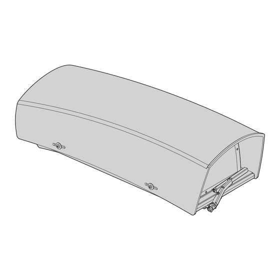
  • Seite 64: Technische Zeichnungen

    11 Technische Zeichnungen Die Abmessungen der Zeichnungen sind in Millimeter angegeben. NUTZ- FLÄCHE NUTZFLÄCHE B - B A - A 4 M16-KABELSHELLEN Abb. 23 HGV. MNVCHGV_1702_DE...
  • Seite 66 Email: info@videotec.com Tel. +33 1 60491816 - Fax +33 1 69284736 Email: info.fr@videotec.com Asia Pacific Videotec (HK) Ltd Americas Videotec Security, Inc. Flat 8, 19/F. On Dak Industrial Building, No. 2-6 Wah Sing Street Gateway Industrial Park, 35 Gateway Drive, Suite 100 Kwai Chung, New Territories - Hong Kong Plattsburgh, NY 12901 - U.S.A.
  • Seite 67 РУССКИЙ Кожух для камеры очень большого размера Русский - Руководство по эксплуатации...
  • Seite 68 Комплект оборудования Р У С С К И Й 1 О настоящем руководстве ..................4 1.1 Типографские условные обозначения ......................4 2 Примечания в отношении авторского права и информация о торговых марках ..........................4 3 Правила техники безопасности ................4 4 Обозначение...
  • Seite 69 10.5 Сертификаты ...............................13 11 Технические чертежи ....................14 MNVCHGV_1702_RU...
  • Seite 70: О Настоящем Руководстве

    1 О настоящем 3 Правила техники руководстве безопасности Внимательно ознакомьтесь со всей ПРЕДУПРЕЖДЕНИЕ! Установка и обслуживание документацией, входящей в комплект поставки, устройства должны осуществляться только перед тем как приступить к установке и специализированным персоналом. эксплуатации данного оборудования. Всегда держите руководство под рукой, чтобы им можно ПРЕДУПРЕЖДЕНИЕ! Система...
  • Seite 71: Обозначение

    4.1 Описание и обозначение национальные правила. типа устройства • Категория установки (также называемая категорией перенапряжения) указывает Кожух HGV идеально подходит для наружного уровень сетевых скачков напряжения, которым наблюдения на дальних дистанциях и подвержено оборудование. Категория зависит обеспечения общественной безопасности, от места размещения оборудования и наличия...
  • Seite 72: Подготовка Устройства К Использованию

    5 Подготовка устройства к 5.3 Безопасная утилизация упаковочных материалов использованию Упаковочные материалы могут подвергаться Любое изменение, которое выполняется переработке. Технический специалист без разрешения, явным образом установщика отвечает за сортировку материалов предоставленного производителем, для переработки, а также за соблюдение аннулирует гарантию. требований...
  • Seite 73: Крепление С Помощью Кронштейна

    6.2 Крепление с помощью Поднимите верхнюю часть корпуса со встроенным козырьком и оставьте ее висеть на крепежном кронштейна шнуре. Прикрепите корпус к кронштейну, используя прилагаемые винты. Рис. 4 Рис. 2 6.4 Снятие направляющих 6.3 Как открыть кожух Для снятия направляющих необходимо открутить крепежные...
  • Seite 74: Использование Распорки H-20

    6.5.1 Использование распорки H-20 Разместите объектив на направляющей (02), поместив между ними пластиковую прокладку Можно установить распорку H-20 (02). Закрепите (01). Закрепите все детали, используя нейлоновую камеру и L-образный кронштейн (6.5 Крепление шайбу и винт 1/4" (03). объектива и камеры, страница 7). Вставьте При...
  • Seite 75: Расположение Салазок

    6.5.2 Расположение салазок Переместите внутреннюю направляющую с уже закрепленными камерой и объективом в необходимое положение и зафиксируйте ее с помощью входящих в комплект шайб и винтов. Рис. 14 Вставьте прокладку между новой пластиной и корпусом. Рис. 12 6.6 Замена пластины с кабельной...
  • Seite 76: Крепление Щетки Стеклоочистителя

    6.7 Крепление щетки 6.7.1 Крепление пластины с соплом стеклоочистителя Закрепите пластину (01) с предварительно собранной форсункой к нижней части корпуса при Наденьте щетку на ось щеткодержателя. помощи двух прилагаемых винтов (02). Рис. 19 При выполнении калибровки струи поверните форсунку в сторону окна Рис.
  • Seite 77: Описание Платы

    6.8 Описание платы 6.9 Подключение линии питания Плата может отличаться от той, что указана на рисунке. ПРЕДУПРЕЖДЕНИЕ! Тип используемого кабеля должен быть совместимым с Плата, в зависимости от версии предполагаемым видом использования. устройства, может не обладать всеми Соблюдайте действующие в вашей функциями.
  • Seite 78: Подключение Стеклоочистителя

    6.10 Подключение 6.11 Подключение сигнального стеклоочистителя устройства вскрытия корпуса Откройте кожух, следуя указаниям в Рабочее напряжение выключателя: макс. соответствующем разделе (6.3 Как открыть кожух, 30Vac или макс. 60Vdc. страница 7). Найдите на плате клемму датчика вскрытия Определите клемму платы стеклоочистителя. (контакты датчика вскрытия, Рис. 20, страница 11). Выполните...
  • Seite 79: Инструкции По Работе В Нормальном Режиме

    7 Инструкции по работе в 10 Технические нормальном режиме характеристики 10.1 Общие сведения Не используйте стеклоочиститель при температуре ниже 0°C или при Основание из алюминия, эпоксиполиэстеровое обледенении. порошковое покрытие, цвет RAL9002 8 Очистка Верхняя часть и солнцезащитный козырек из АБС- материала...
  • Seite 80: Технические Чертежи

    11 Технические чертежи Размеры на чертежах указаны в миллиметрах. B - B A - A Рис. 23 HGV. MNVCHGV_1702_RU...
  • Seite 82 Email: info@videotec.com Тел.: +33 1 60491816 - факс: +33 1 69284736 Email: info.fr@videotec.com Азиатско-Тихоокеанский регион Videotec (HK) Ltd. Americas Videotec Security, Inc. Flat 8, 19/F. On Dak Industrial Building, No. 2-6 Wah Sing Street Gateway Industrial Park, 35 Gateway Drive, Suite 100 Kwai Chung, New Territories - Hong Kong Plattsburgh, NY 12901 - U.S.A.
  • Seite 84 Email: info@videotec.com Tel. +33 1 60491816 - Fax +33 1 69284736 Email: info.fr@videotec.com Asia Pacific Videotec (HK) Ltd Americas Videotec Security, Inc. Flat 8, 19/F. On Dak Industrial Building, No. 2-6 Wah Sing Street Gateway Industrial Park, 35 Gateway Drive, Suite 100 Kwai Chung, New Territories - Hong Kong Plattsburgh, NY 12901 - U.S.A.

Inhaltsverzeichnis