Herunterladen Inhalt Inhalt Diese Seite drucken
Renishaw TS27R Installations- Und Benutzerhandbuch

Renishaw TS27R Installations- Und Benutzerhandbuch

Werkzeugmess-systemzur werkzeugeinstellung
Vorschau ausblenden Andere Handbücher für TS27R:
Inhaltsverzeichnis

Werbung

Verfügbare Sprachen

Verfügbare Sprachen

Installation and user's guide
H-2000-5018-06-D
TS27R tool setting probe
English
Français
Deutsch
Italiano

Werbung

Inhaltsverzeichnis
loading

Inhaltszusammenfassung für Renishaw TS27R

  • Seite 1 Installation and user’s guide H-2000-5018-06-D TS27R tool setting probe English Français Deutsch Italiano...
  • Seite 2 Installation and user's guide TS27R English Tool setting probe Manuel d'installation et d'utilisation Palpeur de réglage Français d’outil TS27R Installations- und Benutzerhandbuch TS27R Werkzeugmess-System Deutsch zur Werkzeugeinstellung Manuale d’installazione e d’uso Sonda per la regolazione Italiano degli utensili TS27R...
  • Seite 3 FCC Section 15.21 The user is cautioned that any changes or modifications not expressly approved by Renishaw plc, or authorised representative could void the user's authority to operate the equipment. FCC Section 15.27...
  • Seite 4: Inhaltsverzeichnis

    Parts list ............1-16 SAFETY The TS27R system must be installed by a competent person, observing relevant safety precautions. Before starting work, ensure that the machine tool is in a safe condition with the power switched OFF and the power supply to the MI 8/MI 8-4 disconnected.
  • Seite 5 © 1995 – 2005 Renishaw plc. All rights reserved. Changes to equipment This document may not be copied or reproduced in Renishaw reserves the right to change whole or in part, or transferred to any other media or specifications without notice.
  • Seite 6: Ts27R Probe System

    MI 8-4 interface control MI 8 interface Machine table T slot The TS27R probe is used for tool setting on Stylus CNC machining centres. Stylus holder for disc or square styli For tool length measurements and broken tool Captive link...
  • Seite 7: Operation

    SOFTWARE ROUTINES RECOMMENDED ROTATING TOOL FEED RATES Software routines for tool setting are available from Renishaw for various machine controllers and are Cutters should be rotated in reverse to the cutting described in data sheet H-2000-2289. direction.
  • Seite 8: Specification

    SPECIFICATION INTERFACE UNIT The MI 8-4 interface is fully Sense directions Normally mounted to sense in the described in user’s guide machine’s ±X, ±Y and –Z axes H-2000-5008. The alternative MI 8 interface is fully described in user’s Uni-directional 1 µm (0.00004 in). guide H-2000-5015.
  • Seite 9: Dimensions

    DIMENSIONS mm (in) OVERTRAVEL OVERTRAVEL 5.5 (0.21) Minimum 10° 50 (1.97) 56 (2.2) at stylus centre in all axes 27 (1.06) 8 (0.31) STYLUS STYLUS PIVOT POINT CONDUIT ADAPTOR MACHINE TABLE Ø54 (Ø2.125) T BOLT ASSEMBLY Ø63.5 (Ø2.5) Two holes To be supplied by user.
  • Seite 10: Installation

    Conduit (supplied in the probe kit) may be fitted on installations where there is a requirement to remove and remount the TS27R. To fit the Spirol ® pins, drill two holes in the machine table to correspond with ®...
  • Seite 11 RECOMMENDED CONNECTION DIAGRAM FOR TS27R PROBE WITH MI 8 INTERFACE MI 8 INTERFACE CNC CONTROLLER ● I/O supply ● B7 SSR Probe status output (voltage free SSR) ● Skip input (G31) ● B6 SSR ● B5 Screen Screen ● Yellow/Green OPTIONAL ●...
  • Seite 12 MACHINE TOOL TS27R TOOL SETTER ● ● Probe+ A1 Blue TS27R PROBE ● ● PROBE Probe– A2 INPUT ● Screen 100 nF For information regarding MI 8 capacitor connections B1 and B2 to the ● CNC controller and input/output Possible earth path...
  • Seite 13 RECOMMENDED CONNECTION DIAGRAM FOR TS27R PROBE WITH MI 8-4 INTERFACE CNC CONTROLLER MI 8-4 INTERFACE ● +V d.c. from I/O supply ● A10 Isolated output + supply ● Skip input (G31) ● A11 Probe status output (totem pole) ● –V d.c. from I/O supply ●...
  • Seite 14 MACHINE TOOL ● Screen TS27R TOOL SETTER ● ● PROBE Probe + A2 Blue INPUT TS27R PROBE ● ● Probe – A3 100 nF For information regarding capacitor ● these connections, please refer to the MI 8-4 user’s Possible earth...
  • Seite 15: Screw Torque Values

    1-10 FITTING THE STYLUS AND CAPTIVE LINK 2 mm AF 2.6 Nm Stylus (1.92 lbf.ft) Stylus holder Break stem Captive link 2 mm AF 1.1 Nm (0.81 lbf.ft) SCREW TORQUE VALUES CAPTIVE LINK Tighten all the screws to the torque values shown, In the event of excessive stylus overtravel, the remembering to use the support bar whenever break stem breaks at its weakest point, preventing...
  • Seite 16: Break Stem

    STYLUS AND HOLDER NOTE Place the stylus and holder onto the break stem and Earlier versions of the TS27R probe were supplied loosely fit grubscrew B. with cup-pointed grubscrews and a different break Fit screw C through the captive link and into the stem.
  • Seite 17: Stylus Level Setting

    1-12 STYLUS LEVEL SETTING TAKE CARE not to stress the break stem Square stylus L3 and L4 Disc stylus 2.5 mm AF 0.8 Nm (0.6 lbf.ft) Side Back Front H, L1 and L2 Side 4 mm AF Screw with 5 Nm spring washer (3.69 lbf.ft) STYLUS TYPES...
  • Seite 18: Square Stylus Alignment

    1-13 SQUARE STYLUS ALIGNMENT L3 and L4 LEVEL Always hold the support bar in 2 mm AF SIDE to SIDE position to counteract twisting 1.1 Nm 2.5 mm AF forces and avoid over-stressing the (0.81 lbf.ft) 0.8 Nm COARSE stylus break stem. (0.6 lbf.ft) ROTATIONAL ADJUSTMENT...
  • Seite 19: Service And Maintenance

    Ensure the probe is firmly secured to its equipment is a highly specialised operation, which mounting. must be carried out at authorised Renishaw Service The probe requires minimal maintenance as it is Centres. designed to operate as a permanent fixture on CNC...
  • Seite 20: Diaphragm Maintenance

    1-15 DIAPHRAGM MAINTENANCE C spanner 4 Nm (2.95 lbf.ft) 2 mm AF 2.6 Nm (1.92 lbf.ft) Break stem Front cover with O ring Captive link 1. Remove the stylus and holder (see page 1-11). 5. Inspect the diaphragm seal for signs of piercing or damage.
  • Seite 21: Parts List

    TS27R holder, probe module, break stem (× 2), disc stylus Ø12.7 mm with MI 8-4 Ø0.5 in) and MI 8-4 interface. TS27R (square) A-2008-0396 TS27R holder, probe module, break stem (× 2), square tip stylus 19 mm with MI 8-4 (0.75 in) and MI 8-4 interface. TS27R (disc) A-2008-0367 TS27R holder, probe module, break stem (×...
  • Seite 22: Consigne De Securite

    Nomenclature ..........2-16 CONSIGNE DE SECURITE Le système TS27R doit être installé par une personne qualifiée respectueuse des consignes de sécurité adéquates. Avant de commencer un travail, vérifier que la machine-outil est sûre, c’est-à-dire que le commutateur de mise sous tension est bien sur OFF (Arrêt) et que l’alimentation en électricité de l’interface...
  • Seite 23 RENISHAW sont des marques déposées de particulier ne reconnaît aucune garantie implicite. Renishaw plc au Royaume Uni et dans d’autres pays. Renishaw se réserve le droit d’apporter des apply innovation est une marque de Renishaw plc.
  • Seite 24: Système De Palpeur Ts27R

    Câble Commande Interface MI 8-4 Interface MI 8 Rainure à T de table de machine-outil Le palpeur TS27R sert au réglage d’outils sur Stylet machine universelle d’usinage à commande Porte-stylet pour stylets à disque ou carrés numérique. Attache de retenue Pour mesurer des longueurs d’outils ou un bris...
  • Seite 25: Opération

    VITESSE D’AVANCE D’OUTIL ROTATIF Les programmes logiciels prévus pour les réglages PRECONISEE d’outil sont disponibles auprès de Renishaw pour Faire pivoter les outils à tourner dans le sens divers contrôleurs de machine (liste à jour opposé à la direction de coupe.
  • Seite 26: Spécification

    SPECIFICATION INTERFACE Normalement installé pour Sens de pose L’interface MI 8-4 fait l’objet d’une palper dans le sens des axes description intégrale dans le manuel ±X, ±Y, –Z de la machine. d’utilisation H-2000-5008. Une 1 µm. Moyenne maximale Répétabilité description intégrale de l’interface MI 8, ✱...
  • Seite 27: Dimensions

    DIMENSIONS dimensions en mm DEPLACEMENT Z DEPLACEMENT X/Y 5,5 au centre 10° minimum du stylet tous axes confondus STYLET PIVOT DU STYLET ADAPTATEUR DE GAINE TABLE DE MACHINE-OUTIL PCD Ø54 ENSEMBLE BOULON POUR RAINURE A T Ø63,5 Deux trous pour A fournir par l’utilisateur goupille Spirol ®...
  • Seite 28: Installation

    Le blindage du câble est connecté à la machine par un Câble à quatre fils 7/0,2 mm à gaine isolante de condensateur de 100 nF à l’intérieur du TS27R pour polyuréthanne blindé de 10 m de long. Diamètre du prévenir tout risque de boucle de terre. S’assurer que le câble 4,4 mm.
  • Seite 29 SCHEMA DE CABLAGE RECOMMANDE POUR LE PALPEUR TS27R AVEC L’INTERFACE MI 8 COMMANDE CNC INTERFACE MI 8 ● Alimentation E/S ● B7 SSR Sortie état palpeur (sortie à relais ● Entrée palpage (G31) ● B6 SSR statique - SSR) ●...
  • Seite 30 MACHINE-OUTIL DISPOSITIF DE REGLAGE D’OUTIL TS27R ● ● Palpeur+ Bleu PALPEUR Rouge TS27R ENTRÉE ● ● Palpeur– PALPEUR ● Blindage Condensateur Pour des informations 100 nF * concernant les connexions B1 ● et B2 de MI 8 à la commande CNC et les connexions d’entrée/...
  • Seite 31 SCHEMA DE CABLAGE RECOMMANDE POUR LE PALPEUR TS27R AVEC L’INTERFACE MI 8-4 INTERFACE MI 8-4 COMMANDE CNC ● +V c.c. de l’alimentation E/S ● A10 Sortie isolée + alimentation ● A11 Sortie état palpeur (montage en totem) Entrée palpage (G31) ●...
  • Seite 32 MACHINE-OUTIL ● Blindage DISPOSITIF DE REGLAGE D’OUTIL TS27R ● ● ENTREE Palpeur + Bleu PALPEUR PALPEUR TS27R Rouge ● ● Palpeur – Condensateur Pour des informations sur ces 100 nF * connexions, consulter le ● manuel de l’utilisateur MI 8-4...
  • Seite 33: Montage Du Stylet Et De L'attache De Retenue

    2-10 MONTAGE DU STYLET ET DE L’ATTACHE DE RETENUE 2 mm AF 2,6 Nm Stylet Porte-stylet Adaptateur fragilisé Attache de retenue 2 mm AF 1,1 Nm COUPLE DE SERRAGE DES VIS ATTACHE DE RETENUE Serrer toutes les vis suivant les couples indiqués en En cas de surcourse excessive du stylet, n’oubliant pas d’utiliser la tige de blocage pour l’adaptateur fragilisé...
  • Seite 34: Adaptateur Fragilisé

    Mettre le stylet et le porte-stylet sur l’adaptateur fragilisé et installer la vis sans tête B sans la serrer. Certaines versions anciennes du palpeur TS27R étaient fournies avec des vis sans tête à pointeau et Faire passer la vis C au travers de l’attache de avec un adaptateur fragilisé...
  • Seite 35: Réglage De Niveau Du Stylet

    2-12 REGLAGE DE NIVEAU DU STYLET ATTENTION: Ne pas soumettre l’adaptateur fragilisé à des forces excessives Stylet carré L3 et L4 Stylet à disque 2,5 mm 0,8 Nm Côté Arrière Avant H, L1 et L2 Côté 4 mm Vis à rondelle 5 Nm élastique TYPES DE STYLET...
  • Seite 36: Alignement Du Stylet Carré

    2-13 ALIGNEMENT DU STYLET CARRE L3 et L4 Toujours tenir la tige de blocage Niveau gauche en place pour compenser les 2 mm à droite forces de pivotement et éviter de 1,1 Nm 2.5 mm soumettre l’adaptateur fragilisé Réglage en 0,8 Nm du stylet à...
  • Seite 37: Entretien Et Maintenance

    Tout démontage et réparation du matériel Veiller à ce que le palpeur soit bien fixé à son Renishaw n’y figurant pas sont des opérations support de montage. hautement spécialisées et doivent par conséquent Etant donné qu’il est conçu pour fonctionner être confiés aux Centres d’Entretien Renishaw...
  • Seite 38: Maintenance De La Membrane

    2-15 MAINTENANCE DE LA MEMBRANE Clé en C 4 Nm 2 mm AF 2,6 Nm Adaptateur fragilisé Couvercle frontal avec joint torique Attache de retenue Retirer le stylet et le porte-stylet (voir page Examiner la membrane d’étanchéité pour vérifier 2-11). qu’elle n’est ni percée, ni endommagée.
  • Seite 39: Nomenclature

    Support TS27R, module palpeur, adaptateur fragilisé (× 2), stylet à touche avec MI 8-4 carrée 19 mm et interface MI 8-4. TS27R (disque) A-2008-0367 Support TS27R, module palpeur, adaptateur fragilisé (× 2 ), stylet à disque avec MI 8 Ø12,7 mm et interface MI 8. TS27R (carré) A-2008-0366 Support TS27R, module palpeur, adaptateur fragilisé...
  • Seite 40: Ts27R Werkzeugmess-System Zur Werkzeugeinstellung

    Teile-Liste ............3-16 SICHERHEITSHINWEIS Das Messtastersystem TS27R darf nur von geschultem Personal unter Einhaltung bekannter Sicherheits- maßnahmen installiert werden. Vor Arbeitsbeginn muss sich die Werkzeugmaschine in einer gesicherten Ausgangsstellung befinden und die Versorgungsspannung der Maschine und für das Interface muss...
  • Seite 41 © 1995 – 2005 Renishaw plc. Alle Rechte vorbehalten. Änderungen der Ausrüstung Dieses Dokument darf ohne vorherige schriftliche Renishaw behält sich vor, die Spezifikation der Genehmigung von Renishaw weder ganz noch Ausrüstung ohne Ankündigung zu ändern. teilweise kopiert oder vervielfältigt werden oder auf...
  • Seite 42: Messtastersystem Ts27R

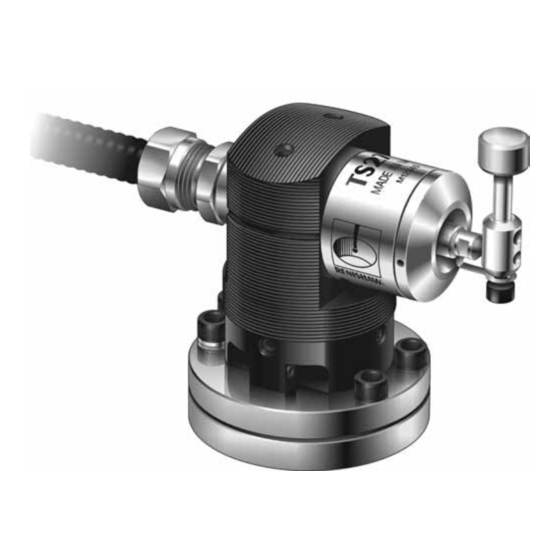
    Maschinen- MI 8-4 Interface steuerung MI 8 Interface Maschinentisch T-Nuten Der Messtaster TS27R wird an CNC-Bearbeitungs- 1. Tastereinsatz zentren zur Werkzeugeinstellung eingesetzt. 2. Halter für Tastscheibe oder Tastplatte Für die Längenmessung und Bruchkontrolle wird 3. Sicherungsband das Werkzeug in der Spindelachse (Z-Achse) gegen den Tastereinsatz gefahren.
  • Seite 43: Betriebshinweise

    Zweites Antasten – Vorschubgeschwindigkeit Werkzeugeinstellungen ausreichend. Drehzahl 800 U/min, Vorschub 4 mm/min. EMPFOHLENE VORSCHUBGESCHWINDIGKEIT SOFTWARE PROGRAMME FÜR DREHENDE WERKZEUGE Renishaw bietet Softwarerroutinen zur Fräser müssen gegen die Schnittrichtung drehend Werkzeugmessung für unterschiedliche angetastet werden. Maschinensteuerungen an. Im Datenblatt Erstes Antasten – Spindeldrehzahl...
  • Seite 44: Spezifikation

    SPEZIFIKATION INTERFACEVERSIONEN Das MI 8-4 Interface wird in der Antastrichtung Bei vertikalem Anbau geeignet zur Bedienungsanleitung H-2000-5008 Antastung in ±X, ±Y, und –Z ausführlich beschrieben. Das MI 8 Wiederholgenauigkeit 1 µm bei 2 Sigma (2σ)* Interface wird ausführlich in der Bedienungsanleitung H-2000-5015 Antastkraft 1,3 N bis 2,4 N (130 gf bis 240 gf)
  • Seite 45: Abmessungen

    ABMESSUNGEN (mm) ÜBERLAUFWEG ÜBERLAUFWEG 5,5 mm Minimum 10° in jeder Achse (bezogen auf Tastermitte) X/Y X/Y TASTEREINSATZ MESSTASTER DREHPUNKT VERSCHRAUBUNG FÜR ANACONDA SCHUTZSCHLAUCH MASCHINENTISCH Teilkreis Ø54 T-NUTSTEIN Ø63,5 Zwei Bohrungen (nicht im Lieferumfang enthalten) für Spannstifte Max. Schraubengröße M12 Ø6,13 mm Ø5,95 mm 45°...
  • Seite 46: Installation

    SPANNSTIFTE (siehe Seite 3-4) Die T-Nuten-Befestigung als Standardbefestigung genügt den normalen Anforderungen. Wenn der Schutz- Messtaster TS27R öfter gelöst und entfernt werden soll, schlauch ist es günstiger, die beiden zusätzlichen Spannstifte (im Lieferumfang enthalten) zu nutzen. Dazu sind zwei Löcher entsprechend der Skizze in den Maschinentisch zu bohren.
  • Seite 47: Verdrahtungsschema Ts27R Mit Mi 8 Interface

    VERDRAHTUNGSSCHEMA TS27R MIT MI 8 INTERFACE MI 8 INTERFACE CNC STEUERUNG B7 SSR I/O Versorgung Tastsignal (potentialfreier B6 SSR Messeingang (G31) SSR-Ausgang) B5 Schirm Schirm Gelb/Grün OPTIONAL ● B1 Inhibit M Befehl Treiber B2 Inhibit 0 V ● ● Gelb/Grün Spannungs- ●...
  • Seite 48 Sperreingang B1 und B2 und Masseverbindung zum Anschluss einer externen erfolgt über die LED (B3-B4) finden Sie im Befestigungs- MI 8-Handbuch H-2000-5015 schraube des TS27R ● ● Externe LED + B3 ● Externe LED – B4 Maschinen-Masse Der 100 nF Kondensator leitet Störspitzen ab bzw.
  • Seite 49: Verdrahtungsschema Ts27R Mit Mi

    VERDRAHTUNGSSCHEMA TS27R MIT MI 8-4 CNC STEUERUNG MI 8-4 INTERFACE ● ● +V d.c. Versorgung Tastsignal A10 +V (Versorgung für Tastsignal) ● ● Messtastereingang (G31) A11 Ausgang Tastsignal ● ● –V d.c. Versorgung Tastsignal A12 -V (Versorgung für Tastsignal) Schirm ●...
  • Seite 50 Kondensator Mehr Information finden ● Sie im MI 8-4 Handbuch Masseverbindung H-2000-5008 Spindel- erfolgt über die messtaster- Befestigungs- OPTIONAL Interface schraube des TS27R ● Eingang + ● Eingang für ● Eingang – Spindel- messtaster Maschinen-Masse ● Schirm Der 100 nF Kondensator leitet Störspitzen ab bzw.
  • Seite 51: Montage Tastereinsatz Und Sicherungsband

    3-10 MONTAGE TASTEREINSATZ UND SICHERUNGSBAND 2 mm Sechskantschlüssel 2,6 Nm Tastereinsatz Sollbruchstück Halter Sicherungsband 2 mm Sechskantschlüssel 1,1 Nm ANZUGSMOMENT SICHERUNGSBAND Um das Sollbruchstück nicht zu beschädigen, Falls der Tastereinsatz bis zur Kollision ausgelenkt muss beim Anziehen/Lösen der Schrauben mit wird, bricht das Sollbruchstück und schützt so den dem Montagegriff gegengehalten werden (siehe Messtaster vor Beschädigung.
  • Seite 52: Tastereinsatz Und Halter

    TASTEREINSATZ UND HALTER Den Tastereinsatz mit dem Halter auf das HINWEIS Sollbruchstück setzen und leicht mit der Schraube B Frühere Versionen des TS27R besitzen ein anziehen. anderes Sollbruchstück und Gewindestifte mit Das Sicherungsband mit Schraube C am Halter Ringschneide. Nur Teile benutzen, die mit diesem befestigen.
  • Seite 53: Tastereinsätze

    3-12 TASTEREINSATZ AUSRICHTEN ACHTUNG: Sollbruchstück nicht beschädigen Tastplatte Tastscheibe L3 und L4 2,5 mm AF 0,8 Nm H, L1 und L2 Schraube mit 4 mm AF Unterlagscheibe 5 Nm TASTEREINSÄTZE Tastscheibe Ø12,7 mm hierdurch gehoben/gesenkt. Sobald die Einstellung Tastplatte 19,05 mm × 19,05 mm stimmt, beide Schrauben L1 und L2 anziehen.
  • Seite 54: Tastplatte Ausrichten

    3-13 TASTPLATTE AUSRICHTEN L3 und L4 Unbedingt den Montagegriff Einstellung der beim Anziehen der Schrauben 2 mm AF oberen Fläche zum Gegenhalten benutzen. 1,1 Nm 2,5 mm AF Ansonsten kann das zur groben 0,8 Nm Sollbruchstück brechen. achsparallelen Einstellung ZUSÄTZLICHE EINSTELLUNG der seitlichen FÜR TASTPLATTE Antastflächen...
  • Seite 55: Service Und Wartung

    Es ist sicherzustellen, dass der Messtaster fest Eine Demontage und Reparatur ist sehr aufwendig und sicher montiert ist. und muss von einem autorisierten Renishaw- Das Messtastersystem erfordert geringe Service-Zentrum durchgeführt werden. Wartungsarbeiten, da es für den permanenten Senden Sie das Mess-System an den Lieferanten Einsatz in CNC-Bearbeitungszentren konzipiert zurück, falls es während der Garantiezeit repariert,...
  • Seite 56: Wartung Der Dichtung

    3-15 WARTUNG DER DICHTUNG Hakenschlüssel 4 Nm 2 mm AF 2,6 Nm Sollbruchstück Frontring mit O-Ring Sicherungsband 1. Tastereinsatz und Halter abnehmen (siehe 5. Die innenliegende flexible Viton-Dichtung auf Seite 3-11). Anzeichen von Undichtigheit oder Beschädigung prüfen. Im Falle von 2.
  • Seite 57: Teile-Liste

    TS27R Messtaster komplett mit Tastscheibe Ø12,7 mm, und Tastscheibe 2 Sollbruchstücken und Interface MI 8-4 TS27R mit MI 8-4 A-2008-0396 TS27R Messtaster komplett mit Tastplatte 19 mm, 2 Sollbruchstücken und Tastplatte und Interface MI 8-4 TS27R mit MI 8 A-2008-0367 TS27R Messtaster komplett mit Tastscheibe Ø12,7 mm,...
  • Seite 58 Elenco parti di ricambio ......4-16 SICUREZZA L’installazione del sistema TS27R è un’operazione riservata ad un tecnico specializzato ed in osservanza delle precauzioni di sicurezza del caso. Prima di accingersi al lavoro, accertarsi che la macchina sia in condizioni di sicurezza e che la tensione di alimentazione alla macchina ed all’interfaccia MI 8/MI 8-4 sia...
  • Seite 59 © 1995 – 2005 Renishaw plc. Tutti i diritti riservati. Modifiche Questo documento non può essere copiato o La Renishaw si riserva il diritto di apportare modifiche alle specifiche delle apparecchiature riprodotto nella sua interezza o in parte, né senza preavviso.
  • Seite 60: Sistema Sonda Ts27R

    Interfaccia MI 8-4 a CN Interfaccia MI 8 Scanalatura a ‘T’ della La sonda TS27R viene usata per la tavola macchina regolazione degli utensili sui centri di lavorazione a CN. 1. Stilo Per la misurazione della lunghezza e il 2.
  • Seite 61: Funzionamento

    PROGRAMMI SOFTWARE VELOCITÀ DI AVANZAMENTO DELL’UTENSILE IN ROTAZIONE La Renishaw ha a disposizione una serie di programmi per la regolazione degli utensili adatti a Far ruotare gli utensili di taglio in senso contrario diverse macchine (richiedete l’elenco direttamente a alla direzione di taglio.
  • Seite 62: Specifiche

    UNITÀ DI INTERFACCIA SPECIFICHE L’unità MI 8-4 è trattata a fondo nel Direzione del Montaggio normale per il rilevamento manuale d’uso H-2000-5008. L’altra rilevamento sugli assi macchina ±X, ±Y e –Z interfaccia MI 8 è trattata nel manuale d’uso H-2000-5015. Ripetibilità...
  • Seite 63 DIMENSIONI mm OLTRECORSA OLTRECORSA ASSE Z ASSI X/Y Minimo 10° 5,5 mm al sui due assi centro dello stilo STILO PUNTO DI ROTAZIONE DELLO STILO RACCORDO TUBO COPRICAVO TAVOLA MACCHINA Ø54 P BULLONE A ‘T’ Ø63,5 Due fori per A carico del cliente ®...
  • Seite 64: Installazione

    Inserire le spine nei fori e quindi riporre la base della La schermatura del cavo è connessa alla sonda. macchina mediante un condensatore da 100 nF posto all’interno della TS27R per CAVO evitare loop di massa. Controllare che la Cavo a quattro fili 7/0,2 in guaina isolata in poliuretano e schermatura del cavo sia collegata al schermato lungh.
  • Seite 65 DIAGRAMMA DELLE CONNESSIONI CONSIGLIATE TRA LA SONDA TS27R CON INTERFACCIA MI 8 ED IL CONTROLLO CNC INTERFACCIA MI 8 CONTROLLO CNC ● ● B7 SSR Alimentazione I/O Uscita stato sonda (relè a stato solido Ingresso skip (G31) ● ● B6 SSR a tensione zero) ●...
  • Seite 66 ● al controllo CNC e sulle Possibile percorso connessioni di ingresso/uscita B3 e B4, fare riferimento al di massa dalle viti manuale dell’utente MI 8, della base a TS27R H-2000-5015 ● ● LED esterno + B3 ● Massa di riferimento della macchina LED esterno –...
  • Seite 67 DIAGRAMMA DELLE CONNESSIONI CONSIGLIATE TRA LA SONDA TS27R CON INTERFACCIA MI 8-4 ED IL CONTROLLO CNC INTERFACCIA MI 8-4 CONTROLLO CNC +V c.c. da alimentazione I/O ● ● A10 uscita isolata alimentazione + ● Ingresso skip (G31) ● A11 uscita stato sonda (ripartizione di alimentazione) -V c.c.
  • Seite 68 ● riferimento al manuale dell’utente MI 8-4, Possibile percorso Interfaccia H-2000-5008 di massa dalle viti della sonda OPZIONALE della base a TS27R di ispezione ● Ingresso + A4 ● Sistema di ispezione ● Ingresso – A5 Massa di riferimento della macchina ●...
  • Seite 69: Valori Di Coppia

    4-10 INSTALLAZIONE DELLO STILO E DEL RACCORDO Chiave a brugola 2 mm Stilo 2,6 Nm Portastilo Snodo a rottura obbligata Raccordo Chiave a brugola 2 mm 1,1 Nm RACCORDO VALORI DI COPPIA In caso di eccessiva sovraccorsa dello stilo lo Stringere tutte le viti ai valori di coppia indicati, snodo a rottura obbligata si spezza nel punto più...
  • Seite 70: Snodo A Rottura Obbligata

    Posizionare stilo e portastilo sullo snodo a rottura obbligata e stringere leggermente il grano B. Le versioni precedenti della sonda TS27R includevano grani a testa tonda e uno snodo di Inserire la vite C nel raccordo fino al portastilo. A tipo diverso.
  • Seite 71: Livellamento Dello Stilo

    4-12 LIVELLAMENTO DELLO STILO ATTENZIONE: non sottoporre lo snodo a rottura obbligata a sforzi eccessivi Stilo quadro L3 e L4 Stilo a disco Chiave a brugola 2,5 mm 0,8 Nm Lato Dietro Davanti Vite con Lato H, L1 e L2 rondella Chiave a brugola 4 mm...
  • Seite 72: Allineamento Dello Stilo Quadro

    4-13 ALLINEAMENTO DELLO STILO QUADRO L3 e L4 Tenere sempre la barra di sostegno in LIVELLAMENTO NEL posizione per contrastare la torsione Chiave a brugola SENSO DELLA ed evitare di sottoporre lo snodo a 2 mm LARGHEZZA rottura obbligata a sforzi eccessivi. 1,1 Nm Chiave a brugola REGOLAZIONE...
  • Seite 73: Servizio E Manutenzione

    Una volta al mese, esaminare la guarnizione interna a diaframma. Se si presenta bucata o danneggiata, rendere l’apparecchio al fornitore per la riparazione. Modificare la frequenza del controllo a seconda delle condizioni d’uso. Guarnizione a palpebra metallica Guarnizione interna a diaframma MODULO SONDA TS27R...
  • Seite 74: Manutenzione Del Diaframma

    4-15 MANUTENZIONE DEL DIAFRAMMA Chiave a ‘C’ 4 Nm Chiave a brugola 2 mm 2,6 Nm Snodo a rottura Pannello obbligata anteriore con guarnizione Raccordo 1. Rimuovere lo stilo e il portastilo (vedere a pagina 4-11). 5. Esaminare attentamente il diaframma e rilevare la presenza di buchi o di danni.
  • Seite 75: Elenco Parti Di Ricambio

    Corpo TS27R, modulo sonda, snodo a rottura obbligata (× 2), stilo a punta con MI 8 quadra 19 mm ed interfaccia MI 8. TS27R (stilo a disco) A-2008-0368 Corpo TS27R, modulo sonda, snodo a rottura obbligata (× 2) e stilo a disco Ø12,7 mm. TS27R A-2008-0388 Corpo TS27R, modulo sonda, snodo a rottura obbligata (×...
  • Seite 76 Renishaw plc +44 (0)1453 524524 New Mills, Wotton-under-Edge, +44 (0)1453 524901 Gloucestershire, GL12 8JR uk@renishaw.com United Kingdom www.renishaw.com For worldwide contact details, please visit our main web site at www.renishaw.com/contact *H-2000-5018-06*...

Inhaltsverzeichnis