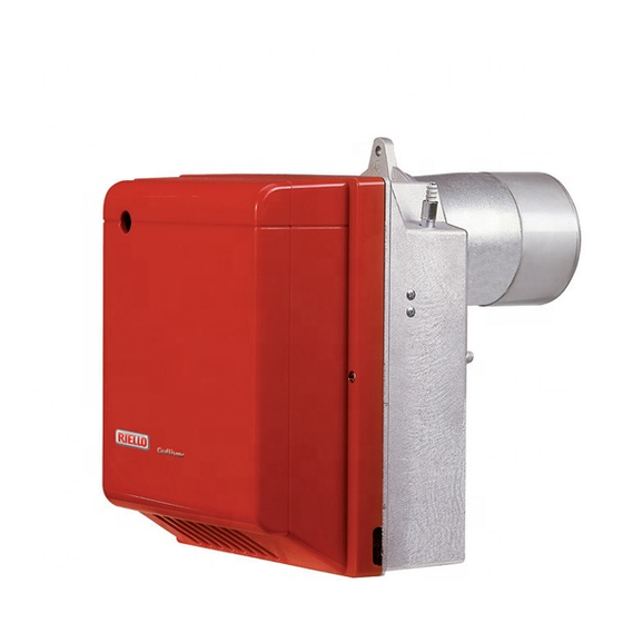
Herunterladen Inhalt Inhalt Diese Seite drucken

Werbung

Verfügbare Sprachen

Verfügbare Sprachen

Montage und Bedienungsanleitung
Installation, use and maintenance instructions
Instrucciones de instalación, montaje y funcionamiento
安装 , 使用以及维护说明书
Öl-Gebläsebrenner
D
Light oil burners
GB
Quemadores de gasóleo
E
轻油燃烧器
CN
Einstufiger betrieb
One stage operation
Funcionamiento a 1 llama
一段火运行
CODE - CÓDIGO
编码
3739650 - 3739655
MODELL - MODEL
MODELO - 型号
RG4S
TYP - TYPE
TIPO - 类型
396T1
2902960 (4) - 05/2016

Werbung

Inhaltsverzeichnis
loading

Inhaltszusammenfassung für Riello RG4S Typ 396T1

  • Seite 1 Montage und Bedienungsanleitung Installation, use and maintenance instructions Instrucciones de instalación, montaje y funcionamiento 安装 , 使用以及维护说明书 Öl-Gebläsebrenner Light oil burners Quemadores de gasóleo 轻油燃烧器 Einstufiger betrieb One stage operation Funcionamiento a 1 llama 一段火运行 MODELL - MODEL TYP - TYPE CODE - CÓDIGO MODELO - 型号...
  • Seite 3: Inhaltsverzeichnis

    INHALT BESCHREIBUNG DES BRENNERS . . . BETRIEB ......1.1 Mitgeliefertes Zubehör ....4.1 Einstellung der Brennerleistung.
  • Seite 4: Technische Merkmale

    TECHNISCHE MERKMALE 2.1 TECHNISCHE DATEN 396 T1 ÷ ÷ Durchsatz - Brennerleistung 20 kg/h – 118,5 237 kW Brennstoff Heizöl-EL (nach DIN 51603, ÖNORM C1109), max. Viskosität bei 20°C: 6 mm ± Stromversorgung Einphase, 50Hz 230 V Motor Stromaufnahme 2 A – 2730 U/min –...
  • Seite 5: Installation

    INSTALLATION 3.1 BRENNERMONTAGE Die Schraube und die beiden Muttern am Flansch (1) montieren, (siehe Abb. 3). ➤ Falls erforderlich, die Bohrungen der Isolierdichtung (4) erweitern, (siehe Abb. 4). ➤ Mit den Schrauben (5) und (falls erforderlich) den Muttern (2) den Flansch (1) an der Kesseltür (3) mit ➤...
  • Seite 6: Ölversorgungsanlage

    3.3 ÖLVERSORGUNGSANLAGE WICHTIGER HINWEIS: ■ Die Pumpe ist werksseitig für den Zweirohr-Betrieb eingerich- tet. Wird ein Pumpen-Einrohrbetrieb für notwendig erachtet, so ist der Zapfen (2) zu lösen und die By-Pass Schraube (3) zu entfernen. Danach ist der Zapfen wieder anzuschließen, (siehe Abb.
  • Seite 7: Elektrisches Verdrahtungsschema

    3.4 ELEKTRISCHES VERDRAHTUNGSSCHEMA ANMERKUNGEN: WICHTIGER HINWEIS – Leiterdurchmesser 1 mm NULLEITER NICHT MIT DER PHASE VERWECHSELN – Die vom Installateur ausgeführten elektrischen Verbindungen müssen den Lokalen Bestim- 50Hz 230V mungen entsprechen. PE L PRÜFUNG Die Regelabschaltung des Brenners kann man überprüfen, indem man die Thermo- Hauptschalter state öffnet.
  • Seite 8: Betrieb

    BETRIEB 4.1 EINSTELLUNG DER BRENNERLEISTUNG In Konformität mit der Wirkungsgradrichtlinie 92/42/EWG müssen die Anbringung des Brenners am Heizkessel, die Einstellung und die Inbetriebnahme unter Beachtung der Betriebsanleitung des Heizkessels ausgeführt werden, einschließlich Kontrolle der Konzentration von CO und CO in den Abgasen, der Abgastemperatur und der mittleren Kesseltemperatur.
  • Seite 9: Brennkopfeinstellung

    4.3 BRENNKOPFEINSTELLUNG (siehe Abb. 12, Seite 6) Sie ist vom Öldurchsatz abhängig und wird ausgeführt, indem man die Einstellschraube (6) im Uhrzeiger- sinn oder entgegen dem Uhrzeigersinn soweit dreht, bis die auf der Einstellspindel markierte Raste (7) mit der Kante am Düsenstock (1) übereinstimmt. In der Abbildung ist der Brennkopf auf einen Durchsatz von 3,50 GPH bei 12 bar eingestellt.
  • Seite 10: Pumpeneinstellung

    ■ EINSTELLUNG DER VOLLAST (siehe Abb. 14, Seite 7) LUFTKLAPPENEINSTELLUNG Die Kontermutter (3) lösen und durch Drehen der Schraube (1) die Anzeige (2) auf die gewünschte Stellung ein- stellen. Dann die Kontermutter (3) wieder festdrehen. PUMPENEINSTELLUNG Wird serienmäßig auf 12 bar eingestellt. Der Manometer zur Druckkontrolle wird anstatt des Verschlusses (4, Abb.
  • Seite 11: Störungen / Abhilfe

    STÖRUNGEN / ABHILFE Nachfolgend finden Sie einige denkbare Ursachen und Abhilfemöglichkeiten für Störungen, die den Betrieb des Brenners beeinflussen oder einen nicht ordnungsgemäßen Betrieb des Brenners verursachen könnten. In den meisten Fällen führt eine Störung zum Aufleuchten der Kontrolleuchte in der Entstörtaste des Steu- ergeräts (3, Abb.
  • Seite 13: Burner Description

    INDEX BURNER DESCRIPTION ... . WORKING ..... . . 1.1 Burner equipment ....4.1 Combustion adjustment.
  • Seite 14: Technical Data

    TECHNICAL DATA 2.1 TECHNICAL DATA TYPE 396 T1 – – Output - Thermal power 20 kg/h 118.5 237 kW Light oil, max. viscosity at 20°C: 6 mm 2 /s Fuel ± Electrical supply Single phase, 50Hz 230 V Motor Run current 2 A –...
  • Seite 15: Boiler Fixing

    INSTALLATION 3.1 BOILER FIXING Put on the flange (1) the screw and two nuts, (see fig. 3). ➤ Widen, if necessary, the insulating gasket holes (4), (see fig. 4). ➤ Fix the flange (1) to the boiler door (3) using screws (5) and (if necessary) the nuts (2) interposing the ➤...
  • Seite 16: Hydraulic Systems

    3.3 HYDRAULIC SYSTEMS WARNING: The pump is designed to allow working with two pipes. In order to obtain one pipe working it is necessary to unscrew the pin (2), remove the by-pass screw (3) and then screw again the pin (2), (see fig. 8). It is necessary to install a filter on the fuel supply line.
  • Seite 17: Electrical Wiring

    3.4 ELECTRICAL WIRING NOTES: WARNING section . – Wires of 1 mm DO NOT EXCHANGE NEUTRAL WITH PHASE – The electrical wiring carried out by the installer must be in compliance with the rules in force in 50Hz 230V the Country. PE L TESTING Check the shut-down of the burner by open-...
  • Seite 18: Combustion Adjustment

    WORKING 4.1 COMBUSTION ADJUSTMENT In conformity with Efficiency Directive 92/42/EEC the application of the burner on the boiler, adjustment and testing must be carried out observing the instruction manual of the boiler, including verification of the CO and CO concentration in the flue gases, their temperatures and the average temperature of the water in the boiler. To suit the required appliance output, choose the proper nozzle and adjust the pump pressure, the setting of the combustion head, and the air damper opening in accordance with the following schedule.
  • Seite 19: Combustion Head Setting

    4.3 COMBUSTION HEAD SETTING (see fig. 12, page 6) It depends on the output of the burner and is carried out by rotating clockwise or counterclockwise the setting screw (6) until the set-point marked on the regulating rod (7) is level with the outside plane of the nozzle-holder assembly (1).
  • Seite 20: Burner Start-Up Cycle

    HIGH-FLAME SETTING (see fig. 14, page 7) AIR-DAMPER ADJUSTMENT Loosen the nut (3), turn the screw (1), until the indicator (2) is in the required position. Then, lock the nut (3). PUMP-ADJUSTMENT This is set at 12 bar at the factory. The pressure gauge must be mounted in place of plug (4, fig.
  • Seite 21 FAULTS / SOLUTIONS Here below you can find some causes and the possible solutions for some problems that could cause a fail- ure to start or a bad working of the burner. A fault usually makes the lock-out lamp light which is situated inside the reset button of the control box (3, fig.
  • Seite 23: Descripción Del Quemador

    ÍNDICE DESCRIPCIÓN DEL QUEMADOR ..1.1 Material suministrado en dotación ..FUNCIONAMIENTO ....4.1 Regulación de la combustión ..DATOS TÉCNICOS .
  • Seite 24: Datos Técnicos

    DATOS TÉCNICOS 2.1 DATOS TÉCNICOS TIPO 396 T1 ÷ ÷ Caudal - Potencia térmica 20 kg/h – 118,5 237 kW ÷ Combustible Gasóleo, viscosidad 4 6 mm /s a 20 °C Alimentación eléctrica Monofásico, ± 50Hz 230 V Motor Corriente absorbida 2 A –...
  • Seite 25: Fijación A La Caldera

    INSTALACIÓN 3.1 FIJACIÓN A LA CALDERA Introducir en la brida (1) el tornillo y las dos tuercas, (véase fig. 3). ➤ Alargar, si es necesario, los orificios de la junta aislante (4), (véase fig. 4). ➤ Fijar a la puerta de la caldera (3) la brida (1) mediante los tornillos (5) y (si es necesario) las tuercas (2) ➤...
  • Seite 26: Cebado De La Bomba

    3.3 INSTALACIÓNES HIDRÁULICAS ATENCIÓN: La bomba está preparada para funcionar con un sistema de dos tubos. Para el funcionamiento con un sistema de un tubo es preciso el perno (2), quitar el tornillo de by-pass (3), y luego enroscar otra vez el perno (2) (véase fig. 8). Es necesario instalar un filtro alimentación del combustible.
  • Seite 27: Conexiones Eléctricas

    3.4 CONEXIONES ELÉCTRICAS NOTAS: ATENCIÓN ➤ La sección de los conductores debe ser de mín. 1 mm (Salvo indicaciones diferentes de normas y leyes locales). NO INTERCAMBIAR EL NEUTRO CON LA FASE ➤ Las conexiones eléctricas efectuadas por el instalador de- ben respetar la normativa vigente en el país.
  • Seite 28: Regulación De La Combustión

    FUNCIONAMIENTO 4.1 REGULACIÓN DE LA COMBUSTIÓN En conformidad con la Directiva de Rendimiento 92/42/CEE la aplicación del quemador a la caldera, la regulación y la prueba deben realizarse respetando el manual de instrucciones de la caldera, incluyendo el control de la con- centración de CO y CO en los humos, su temperatura y la temperatura media del agua de la caldera.
  • Seite 29 4.3 REGULACIÓN DEL CABEZAL, (véase fig. 12, pág 6) Es en función de la potencia del quemador y se realiza rotando en sentido horario o anti horario en tornillo de regulación (6) hasta que la muesca de la brida de regulación (7) coincida con el plano exterior del conjunto portaboquilla (1).
  • Seite 30 REGULACIÓN ALTA LLAMA (véase fig. 14, pág. 7) REGULACIÓN REGISTRO DE AIRE Afloje la tuerca (3), gire el tornillo (1) y lleve el indicador (2) a la posición deseada. Después bloquee la tuerca (3). REGULACIÓN BOMBA En fábrica se calibra a 12 bar. El manómetro para controlar la presión se monta en el lugar del tapón (4, fig.
  • Seite 31: Anomalías / Soluciones

    ANOMALÍAS / SOLUCIONES Se enumeran algunas causas y posibles soluciones a una serie de anomalías que podrían producirse y provo- car el no funcionamiento o funcionamiento irregular del quemador. Una anomalía del funcionamiento en la mayor parte de los casos, provoca el encendido de la señalización dentro del pulsador de desbloqueo de la caja de control (3, fig.
  • Seite 33 目录 燃烧器描述 ..... . . 工作 ......1.1 燃烧器附件...
  • Seite 34 技术参数 2.1 技术参数 类型 396 T1 热出力 – – 20 kg/h 118.5 237 kW 燃料 轻油 , 在 20 °C 时粘度 4 – 6 mm 电源 单相 , ± 50Hz 230 V 马达 运行电流 2 A – 2730 rpm – 286 rad/s 6.3 µF 电容...
  • Seite 35 安装 3.1 锅炉安装 将螺栓和螺母放在法兰 (1) 上 , ( 参见图 . 3). ➤ 如有必要,对石棉垫扩孔 (4), ( 参见图 . 4). ➤ 用螺栓 (5) 和螺母 (2) 将法兰 (1) 安装到炉门 (3) 上, 必须将石棉垫 (4) 放在中间 , ( 参见图 . 2). ➤ 安装后,确保燃烧器如 图 5 所示,燃烧器微微向上倾斜 . ➤...
  • Seite 36 3.3 液压系统 警告 : 设计时泵是按双管运行的。如单管运行,须拧下回油螺钉 (2), 移开 旁路螺钉 (3) 后再拧紧螺钉 (2). ( 参见图 .8). 在供油管路上必须装滤网 . 启动燃烧器之前, 确保回油管无堵塞 . 过大的背压会使泵的密封损坏 D5527 L (m) I. D. I. D. (m) 图 . 7 8 mm 10 mm 图 . 8 供油管 D5745 回油管...
  • Seite 37 3.4 电气连接 注意 : 警告 – 电线截面积:1 mm 不要将火线与零线接反 – 连线的安装必须符合所在国家的强制规定 . 50Hz 230V PE L 试验 : – 断开温控器开关,检查燃烧器是否停机 . 主开关 – 遮黑光电管,检查燃烧器是否锁定 . 计时器 (230V - 0.1A max.) 安全温控器 温控器 远程锁定信号 (230V - 0.5A max.) 7 针插头 7 孔插座 光电管...
  • Seite 38 工作 4.1 燃烧调节 根据效率标准 92/42/EEC, 调试燃烧器必须参考锅炉的使用说明 , 这一工作包括调整烟气中的 CO 和 CO , 烟温 及锅炉中的平均水温。 要达到所需要的出力,应按照下表选择合适的喷嘴,调整泵压,设定燃烧头和风门 . 表中的数值由 CEN 锅炉测得 ( 按照 EN 267). 参考条件:12.5% CO 2 ,在海平面,油温和室温为 20 °C. 风门调节 喷嘴 泵压 燃烧器输出 燃烧头设置 小火 大火 角度 设定点 设定点 设定点 kg/h ±...
  • Seite 39 4.3 燃烧头设定 ( 参见图 . 12,P.6) 根据燃烧器的出力 , 通过顺时针和逆时针转动设定螺丝 (6) 来进行 , 直到设定的调节杆 (7) 上的刻度点与喷嘴座 (1) 的外边缘对齐 . 在简图中 , 燃烧器的设定对应于 3.50 GPH 油压为 12 bar 时的出力 . ➤ 如图所示 , 调节杆 (7) 上的设定点 2.5 与喷嘴座 (1) 的外边缘对齐 . 4.4 电极的调整 ( 参见图...
  • Seite 40 大火的设定 ( 参见图 . 14, P 7) 风门调节 松开螺母 (3), 转动螺钉 (1), 直到指示器 (2) 在所需的位置 . 然后锁定螺母 (3). 泵压调节 出厂设定为 12 bar . 压力表必须安装在接口处 (4, 图 . 8, P 4). 如有必要重新设定压力或调节这个压力 , 可调节压力调节螺钉 (5, 图 . 8,P 4). 燃烧器关机后 , 风门会自动关闭 , 除非烟囱处的最大负压力超过 0.5mbar. 4.6 燃烧器启动程序...
  • Seite 41 故障 / 解决方法 下面是造成启动故障或燃烧器非正常运行等问题的原因及相应的解决方法 . 故障通常会造成位于控制盒 (3, 图 . 1, P. 1) 复位按钮键中的锁定指示灯亮 . 当锁定灯亮时 , 只有按复位按钮燃烧器才会重新启动 , 此后如果燃烧器运行正常 , 锁定可以归因于暂时故障 . 如果继续锁定 , 一定要查找原因 , 并加以解决 . 故障 可能的原因 解决方法 检查 7 针插头中的 L1-N 线之间的电压是 否存在 . 无电源 . 检查保险丝的状况...
  • Seite 44 RIELLO S.p.A. I-37045 Legnago (VR) Tel.: +39.0442.630111 http:// www.riello.it http:// www.riello.com Änderungen vorbehalten! - Subject to modifications - Con la posibilidad de modificación - 保留更新的权利...

Inhaltsverzeichnis