Inhaltsverzeichnis
Werbung
Verfügbare Sprachen
Verfügbare Sprachen
Quicklinks
URBAN 125/200cc
Grazie per la fi ducia accordata e buon divertimento. Con questo
libretto abbiamo voluto darLe le informazioni necessarie per un
corretto uso e una buona manutenzione della Sua moto.
I dati e le caratteristiche indicate sul presente manuale non impegnano la
BETAMOTOR S.p.A che si riserva il diritto di apportare modifi che e migliora-
menti ai propri modelli in qualsiasi momento e senza preavviso.
I
1
Werbung
Kapitel
Inhaltsverzeichnis

Verwandte Anleitungen für Beta URBAN 125 cc


Inhaltszusammenfassung für Beta URBAN 125 cc
- Seite 1 URBAN 125/200cc Grazie per la fi ducia accordata e buon divertimento. Con questo libretto abbiamo voluto darLe le informazioni necessarie per un corretto uso e una buona manutenzione della Sua moto. I dati e le caratteristiche indicate sul presente manuale non impegnano la BETAMOTOR S.p.A che si riserva il diritto di apportare modifi...
- Seite 2 AVVERTENZA Si raccomanda, dopo la prima o seconda ora di utilizzo in fuori- strada, di controllare tutti i serraggi con particolare attenzione a: • corona • supporti pedane • pinza freno anteriore • pinza freno posteriore • portatarga • cavallotti manubrio •...
-
Seite 3: Inhaltsverzeichnis
Avvertenze sull’uso .................. 5 Guida ecologica ..................5 Guida sicura ..................6 CAP. 1 INFORMAZIONI GENERALI ........... 7 Dati identifi cazione veicolo ..............8 Fornitura ....................8 Carico ....................9 Pneumatici .................... 9 Conoscenza del veicolo ................ 10 Chiavi ....................12 Commutatore / bloccasterzo .............. - Seite 4 CAP. 4 REGOLAZIONI ..............65 Regolazione freni ................66 Regolazione frizione ................66 Regolazione minimo ................67 Regolazione fl usso benzina ..............67 Regolazione gioco gas ................. 67 Controllo e regolazione gioco sterzo............68 Tensionamento catena ................69 Fascio luminoso ................... 70 CAP.
-
Seite 5: Avvertenze Sull'uso
AVVERTENZE SULL’USO DEL VEICOLO • Il veicolo deve essere obbligatoriamente corredato di: targa, libretto di circolazione, bollo ed assicurazione. • È vietato il trasporto di animali e oggetti non resi solidali al veicolo, che sporgono dall’ingombro del veicolo stesso e che superino il carico previsto dal Costruttore. •... -
Seite 6: Guida Sicura
GUIDA SICURA • Rispettare il Codice Stradale • Indossare sempre casco omologato ed allacciato • Mantenere sempre pulita la visiera protettiva • Indossare indumenti senza estremità penzolanti • Non viaggiare con in tasca oggetti acuminati o fragili • Regolare correttamente lo specchietto retrovisore •... -
Seite 7: Cap. 1 Informazioni Generali
INDICE ARGOMENTI CAP. 1 INFORMAZIONI GENERALI Dati identifi cazione veicolo Fornitura Carico Pneumatici Conoscenza del veicolo Chiavi Commutatore / bloccasterzo Serratura casco Cruscotto e comandi Indicazioni su LCD Dati tecnici Schema elettrico Dispositivi elettrici Valvola AIS... - Seite 8 DATI IDENTIFICAZIONE VEICOLO I dati di identifi cazione A sono impressi sul canotto dello sterzo nel lato destro. I dati di identifi cazione B del motore sono impressi nella zona indicata in fi gura. ATTENZIONE: l’alterazione dei numeri di identifi cazione è...
- Seite 9 CARICO • Carico massimo (conducente + passeggero): 280 Kg. • Non trasportare assolutamente oggetti voluminosi o troppo pesanti, che potrebbero pregiudicare la stabilità del veicolo. • Non trasportare oggetti che sporgano dal veicolo o che coprano i dispositivi d’illuminazione e di segnalazione. PNEUMATICI Pneumatico Anteriore...
-
Seite 10: Conoscenza Del Veicolo
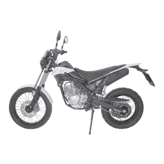
CONOSCENZA DEL VEICOLO... - Seite 11 Elementi principali: 1 - Filtro aria 2 - Serbatoio carburante 3 - Tappo carburante 4 - Silenziatore 5 - Ammortizzatore po ste riore 6 - Faro anteriore 7 - Indicatori di direzione anteriori 8 - Fanale posteriore 9 - Indicatori di direzione posteriori 10 - Cavalletto laterale 11 - Specchi retrovisori 12 - Pedane passeggero...
-
Seite 12: Chiavi
CHIAVI E SERRATURE Il veicolo viene fornito con due chiavi en- trambi, da utilizzare per il commutatore/ bloccasterzo e per la serratura casco. ATTENZIONE: Non conservare la chiave di scorta all’interno del veicolo, ma in luogo sicuro ed a portata di mano. Consigliamo di registrare sul presente manuale (o altrove) il numero di codice impresso sulle chiavi. -
Seite 13: Cruscotto E Comandi
CRUSCOTTO E COMANDI 1 - LCD 10 - Manopola acceleratore 2 - Tasto MODE 11 - Pulsante accensione 3 - Spia indicatori direzione 12 - Pulsante stop motore 4 - Spia accensione luci abbaglianti 13 - Pulsante indicatori di direzione 5 - Spia indicatore folle 14 - Pulsante clacson 6 - Spia cavalletto abbassato... -
Seite 14: Istruzioni Di Settaggio E Funzionamento Contachilometri
ISTRUZIONI DI FUNZIONAMENTO CONTACHILOMETRI Serie Urban 125-200 cc INDICE DEGLI ARGOMENTI STRUMENTAZIONE DI BORDO FUNZIONI STRUMENTAZIONE Velocità istantanea Distanza totale (TOTAL) Distanza parziale (TD) Cronometro (LAP) Velocità massima (MAX) Standby Livello carica batteria Orologio 2.8.1 Regolazione orologio GESTIONE ALLARMI Allarme tensione batteria SPIE DI SEGNALAZIONE E RETROILLUMINAZIONE Spia Indicatori di direzione Spia Abbaglianti... - Seite 15 1. STRUMENTAZONE DI BORDO Tachimetro Icona batteria TOTAL: chilometri totali percorsi TD: totalizzatore parziale TIME: orologio LAP: cronometro Pulsante Mode Spia cavalletto laterale Velocità istantanea 10 Spia Frecce 11 Spia luce abbaglianti 12 Spia folle...
-
Seite 16: Funzioni Strumentazione
2. FUNZIONI STRUMENTAZIONE 2.1 Velocità istantanea L'informazione viene sempre visualizzata sul digit 10÷12 (fi g. 1 e fi g. 2). Se l'unità di misura selezionata è Km/h (valore di default), viene visualizzato il logo relativo; agendo sul pulsante ed Fig. 1 accedendo al menu di Set-Up, è... -
Seite 17: Distanza Parziale (Td)
2.3 Distanza parziale (TD) Questa funzione descrive il funziona- mento/visualizzazione del totalizzatore parziale automatico di bordo. Tale funzione viene sempre rappresentata utilizzando i digit 1÷5 e la scritta TD (fi g. 5). Il dato visualizzato rappresenta la distanza percorsa dal veicolo espressa in miglia o in Km (secondo l'unità... -
Seite 18: Cronometro (Lap)
2.4 Cronometro (LAP) Questa funzione descrive il funzionamen- to/visualizzazione del cronometro. L'informazione viene visualizzata utilizzan- do i digit 1÷5 e la scritta LAP. Per accedere al menu del cronometro, bisogna tenere premuto il pulsante in corrispondenza della schermata come mostrato in fi gura 6 fi no alla comparsa del cronometro (fi... - Seite 19 Disattivazione: è possibile fermare il cronometro nel seguente modo: 1) in automatico se la velocità = 0 Se la velocità diventa = 0, il cronometro si ferma, anche se l'attivazione è stata data da pulsante. Azzeramento: è possibile azzerare il cronometro tramite una pressione lunga (>5 sec.) del pulsante.
-
Seite 20: Velocità Massima (Max)
2.5 Velocità massima (MAX) Questa funzione descrive il funzionamen- to/visualizzazione della funzione velocità massima. L'informazione viene visualizzata utilizzan- do i digit 2÷5 e la scritta MAX, come mostrato in fi g. 9. Il parametro identifi ca la velocità mas- sima raggiunta dal veicolo, espressa in Km/h o in mph secondo l'unità... -
Seite 21: Livello Carica Batteria
2.7 Livello carica batteria L'informazione viene visualizzata ricorren- do alla barra grafi ca nella parte inferiore sinistra, così come mostrato in fi gura 11. La barra grafi ca, aggiornata ogni 4 se- condi, viene gestita secondo la seguente Fig. 11 tabella (tolleranza ±0,1 V): Tensione (Volt) Segmenti attivi... -
Seite 22: Regolazione Orologio
2.8.1 Regolazione orologio La regolazione dell'orologio è possibile solo a veicolo fermo mantenendo pre- muto il pulsante per circa 5 secondi in corrispondenza nella funzione standby. La regolazione sarà possibile quando resteranno attivi solo i segmenti relativi all'orologio, mentre tutti gli altri segmenti vengono spenti (fi... - Seite 23 In questo caso, durante la regolazione, comparirà sul digit 10 e 11 la scritta AM oppure sul digit 11 e 12 la scritta PM come mostrato in fi gura 14. N.B. Durante la permanenza nel menu di Set-Up l'orologio NON viene aggiornato.
-
Seite 24: Gestione Allarmi
3. GESTIONE ALLARMI 3.1. Allarme tensione batteria Ogni volta che il valore di tensione rile- vato diventa minore di 10,0 V (±0,1 V), il sistema attiva la routine di allarme per segnalare la possibilità che, in seguito ad avviamento del veicolo, il cruscotto perda le sue impostazioni. -
Seite 25: Retroilluminazione Lcd E Quadrante
4.5 Retroilluminazione LCD e quadrante La retroilluminazione del cristallo è di colore orange. La retroilluminazione sempre accesa se il blocco chiave è in posizione ON. 5. MENU' DI SET-UP L'ingresso nel menu di Set-Up è possibile solo a veicolo fermo premendo il pulsante per circa 5 secondi in corrispondenza della funzione TOTAL. - Seite 26 5.1 Modifi ca unità di misura Saranno visualizzati solo i simboli Km/h e mph con l'unità selezionata che verrà mostrata lampeggiante (con f=1Hz, Duty=50%) (fi g. 16). Una breve pressione del pulsante cambia l'unità selezionata, mentre una pressione Fig. 16 lunga permette di passare alla regolazio- ne successiva oppure di uscire dal menu di Set-Up.
-
Seite 27: Successione Delle Funzioni Rappresentate
Successione delle funzioni rap- presentate Lo scroll delle funzioni è sempre possibile, sia a veicolo fermo che in movimento, agendo sul pulsante, secondo la sequenza indicata nella tabella sottostante: TOTAL distanza percorsa totale distanza percorsa parziale tempo sul giro velocità massima STDBY regolazione orologio... -
Seite 28: Start-Up (Avviamento Del Sistema)
7. START-UP (AVVIAMENTO DEL SISTEMA) All'accensione della strumentazione il sistema visualizza per l'utente una serie di informazioni che, per semplicità ven- gono rappresentate su schermate (pagine) successive: ● I pagina (ad ogni collegamento con la batteria veicolo): Versione e data di rilascio del software (per circa 3 secondi) (fi... - Seite 29 8. SLEEP-MODE E WAKE-UP SLEEP MODE - Il microcontrollore entra nella fase di sleep, caratterizzata da basso assorbimento di corrente quando il sottochiave è portato sulla posizione OFF. Per raggiungere questo scopo, durante la fase di sleep qualsiasi attività svolta normalmente dalla strumentazione viene sospesa, il display e la sua retroillumi- nazione vengono spenti e rimane attivo...
-
Seite 30: Dati Tecnici Generici
DATI TECNICI CARICO MASSIMO conducente + passeggero ...............280 (kg) PESO VEICOLO in ordine di marcia (a secco) URBAN 200 .........103 (kg) in ordine di marcia (a secco) URBAN 125 ........101 (Kg) DIMENSIONI lunghezza totale ................2143 mm larghezza totale ................820 mm altezza totale ................1170 mm interasse ..................1372 mm altezza sella .................836 mm... -
Seite 31: Sospensione Anteriore
SOSPENSIONE ANTERIORE forcella idraulica con steli di Ø 37 mm. Quantità olio per stelo: destro ..................310 ± 5 cc sinistro ..................310 ± 5 cc Tipo olio ................SHELL EBH 16 Livello olio ..........142 mm dal bordo superiore del tubo con forcella a fi... - Seite 32 MOTORE URBAN 125 tipo........Monocilindrico, inclinato in avanti, 4 tempi, SOHC alesaggio x corsa ..............54x54 mm cilindrata (cm ) ................124 cm rapporto di compressione ..............10:1 carburatore ............Ø26-38 MIKUNI UCAL 5Nh lubrifi cazione ..............Forzata con pompa alimentazione ..
- Seite 33 MOTORE URBAN 200 tipo.......... Monocilindrico a quattro tempi SUZUKI H402 alesaggio x corsa ..............66x58,2 mm cilindrata (cm ) ................199 cm rapporto di compressione ..............9,4:1 carburatore ............... MIKUNI BST31 42AD lubrifi cazione ..............con olio in coppa alimentazione ..........a benzina (con numero di ottano minimo 95 senza piombo) mediante carburatore raffreddamento ............
-
Seite 34: Schema Elettrico Urban 125
SCHEMA ELETTRICO URBAN 125... - Seite 35 SCHEMA ELETTRICO URBAN 125 INDICATORE ANTERIORE DESTRO (LAMPADA 12V-10W) PULSANTE STOP ANTERIORE GRUPPO COMANDI DESTRO ARRESTO MOTORE PULSANTE AVVIAMENTO SPIA CAVALLETTO SPIA FOLLE SPIA ABBAGLIANTI SPIA FRECCE DISPLAY SENSORE GIRI RUOTA PROIETTORE LAMPADA BILUCE (12V-5560W) LAMPADA POSIZIONE 12V-5W PULSANTE CLACSON PULSANTE FLASH DEVIATORE LUCI COMMUTATORE LAMPEGGIATORI...
-
Seite 36: Schema Elettrico Urban 200
SCHEMA ELETTRICO URBAN 200... - Seite 37 SCHEMA ELETTRICO URBAN 200 INDICATORE ANTERIORE DESTRO (LAMPADA 12V-10W) PULSANTE STOP ANTERIORE GRUPPO COMANDI DESTRO ARRESTO MOTORE PULSANTE AVVIAMENTO SENSORE GIRI RUOTA DIODO 1A SPIA FOLLE SPIA ABBAGLIANTI SPIA FRECCE DISPLAY SPIA CAVALLETTO PULSANTE CLACSON PULSANTE FLASH DEVIATORE LUCI COMMUTATORE LAMPEGGIATORI GRUPPO COMANDO SINISTRO PULSANTE FRIZIONE INDICATORE ANTERIORE SINISTRO (LAMPADA 12V-10W)
-
Seite 38: Dispositivi Elettrici
DISPOSITIVI ELETTRICI BATTERIA Si accede alla batteria A rimuovendo la sella, come descritto nella sezione “Rimo- zione delle carrozzeria” a pagina 58. Rimuovere il coperchio B svitando la vite C, sganciare l’elastico D scollegare i cavi e rimuovere la batteria. ATTENZIONE: Per evitare danni all’impianto elettrico, non scollegare mai i cavi con il motore... -
Seite 39: Regolatore Di Tensione
INTERMITTENZA L’intermittenza G si trova sotto il serba- toio ed è raggiungibile rimuovendo la fi ancatina destra sotto al serbatoio come descritto a pagina 59. BOBINA A.T. - RELE AVVIAMENTO - RELE CAVALLETTO - FUSIBILE In posizione centrale, sul lato sinistro del veicolo si trovano: la bobina H, il relè... -
Seite 40: Valvola Ais
VALVOLA AIS Si chiama AIS ed è un sistema d’immis- sione d’aria che consente di completare la combustione di quella parte di idro- carburi incombusti, residuo del ciclo termodinamico. Per accedere alla valvola A è necessario rimuovere la protezione destra sotto il serbatoio come descritto a pagina 58... -
Seite 41: Cap. 2 Utilizzo Del Veicolo
INDICE ARGOMENTI CAP. 2 UTILIZZO DEL VEICOLO Controlli e manutenzione prima e dopo l’utilizzo in fuoristrada Lubrifi canti e liquidi consigliati Rodaggio Avviamento del motore Arresto del motore Rifornimento carburante... - Seite 42 CONTROLLI E MANUTENZIONE PRIMA E DOPO L’UTILIZZO IN FUORISTRADA Onde evitare spiacevoli inconvenienti durante il funzionamento del veicolo è con- sigliabile effettuare, sia prima che dopo l’utilizzo, alcune operazioni di controllo e manutenzione. Infatti pochi minuti dedicati a queste operazioni, oltre a rendere la guida più...
-
Seite 43: Specifiche Tecniche
LUBRIFICANTI E LIQUIDI CONSIGLIATI Per un migliore funzionamento ed una più lunga durata del mezzo si raccomanda di utilizzare preferibilmente i prodotti elencati in tabella: TIPO DI PRODOTTO SPECIFICHE TECNICHE OLIO MOTORE BARDAHL XTM 15W 50 OLIO FRENI BARDAHL BRAKE FLUID DOT4 OLIO PER FORCELLE SHELL EBH 16 GRASSO PER TIRANTERIE... -
Seite 44: Avviamento Del Motore
AVVIAMENTO DEL MOTORE • Posizionare il rubinetto del serbatoio Aperto carburante in posizione APERTO (vedi Chiuso Riserva disegno accanto). • Ruotare la chiave nel commutatore in senso orario ed assicurarsi che la spia del folle, posta sul cruscotto, sia accesa (vedi richiamo 5 a pagina 13). -
Seite 45: Starter
STARTER L’attivazione dello starter facilita l’avvia- mento a motore freddo, per inserire tale dispositivo procedere come segue: • Azionare la leva start D premendola verso l’nterno. • Attendere circa 2 minuti per scaldare il motore, senza ruotare la manopola gas, quindi riportare la leva start D nella posizione iniziale. -
Seite 46: Rifornimento Carburante
RIFORNIMENTO CARBURANTE •Spegnere il motore. • Rimuovere il tappo A. Nota: La capacità del serbatoio è di circa 6 litri di cui 1 di riserva. ATTENZIONE: La benzina è estremamente infi ammabile. Eventuali trabocchi di benzina sulla car- rozzeria o su altre parti, devono essere prontamente rimossi. -
Seite 47: Cap. 3 Controlli E Manutenzione
INDICE ARGOMENTI CAP. 3 CONTROLLI E MANUTENZIONE Olio motore e fi ltro olio Tubo raccolta fumi Olio pompa freni, spurgo freni Olio forcelle Filtro aria Candela Freni: anteriore, posteriore Batteria Rimozione carrozzeria Pulizia del veicolo e controlli Manutenzione programmata Lunga inattività del veicolo... - Seite 48 OLIO MOTORE E FILTRO OLIO UR- BAN200 Controllo Tenere il veicolo in posizione verticale rispetto al terreno. A motore freddo controllare, attraverso la spia livello olio A, il livello dell’olio che non deve mai scendere sotto la spia. Per ripristinare il livello, procedere al rabbocco attraverso il tappo di carico B.
- Seite 49 • Inserire il coperchio fi ltro olio, dopo aver montato molla ed O-Ring e serrare i tre dadi di fi ssaggio C. • Introdurre la giusta quantità di olio: - cambio olio ....... 850 ml - con cambio fi ltro ....950 ml - revisione ......
-
Seite 50: Olio Motore E Fi Ltro Olio Urban125
OLIO MOTORE E FILTRO OLIO URBAN125 Controllo Tenere il veicolo in posizione verticale rispetto al terreno. A motore freddo controllare la presenza dell’olio. Rabbocco Per ripristinare il livello procedere al rabbocco attraverso il tappo A Sostituzione Eseguire sempre la sostituzione dell’olio a motore caldo, facendo attenzione a non toccare il motore e l’olio stesso onde evitare scottature. -
Seite 51: Tubo Raccolta Fumi
TUBO RACCOLTA FUMI Il tubo raccolta fumi A è situato sulla parte sinistra del veicolo vicino all’ammortiz- zatore, esce dalla parte inferiore del manicotto di aspirazione e raccoglie i gas prodotti dall’olio motore. Nel caso si riscontrasse la presenza di olio all’interno del tubo, questo deve essere svuotato, togliendo il tappo all’estremità... - Seite 52 Spurgo freno anteriore Per lo spurgo aria dal circuito del freno anteriore procedere come segue: • Togliere il cappuccio di gomma A dalla valvola B. • Aprire il tappo della vaschetta olio C. • Inserire un’estremità di un tubicino nella valvola B, e l’altra all’interno di un contenitore.
-
Seite 53: Olio Forcelle
OLIO FORCELLE Steli La descrizione relativa alla sostituzione dell’olio delle forcelle riveste un carat- tere puramente informativo. Infatti è consi gliabile rivolgersi ad un’offi cina autorizzata BETAMOTOR per effettuare questa operazione. Per la sostituzione procedere nel modo seguente: Allentare la vite A di serraggio dello stelo. -
Seite 54: Filtro Aria
FILTRO ARIA Si accede al gruppo fi ltro A rimuovendo la sella, come descritto nella sezione “Rimo- zione della carrozzeria” a pagina 58. • Rimuovere il coperchio B svitando la vite C. • Sollevare il supporto batteria come indicato in fi gura, •... -
Seite 55: Candela
CANDELA Effettuare l’operazione uti- lizzando guanti protettivi onde evitare scottature. Mantenere la candela in buono stato contribuisce alla diminuzione dei consumi e all’ottimale funzionamento del motore. È preferibile rimuovere la candela a motore caldo (ovviamente spento) in quanto i depositi carboniosi e la colo- razione dell’isolamento forniscono im- portanti indicazioni sulla carburazione, sulla lubrifi... -
Seite 56: Freno Anteriore
FRENO ANTERIORE Controllo Per verifi care lo stato di usura del freno anteriore è suffi ciente visionare la pinza dalla parte anteriore, dove è possibile intravedere le estremità delle due pasti- glie che dovranno presentare almeno uno strato di 2 mm di ferodo. Nel caso lo strato fosse inferiore procedere imme- diatamente alla loro sostituzione (vedi sezione 5 “Sostituzioni”... -
Seite 57: Batteria
BATTERIA Verifi care lo stato di carica della batteria, misurando la tensione con batteria a ri- poso “Veicolo spento” con un voltmetro. Il voltaggio non deve essere inferiore a 12,8V. Non è necessario controllare il livello dell’elettrolita o rabboccare con acqua. Tenere puliti i poli della batteria e se necessario, ingrassarli leggermente con grassi privi di acidi. -
Seite 58: Rimozione Carrozzeria
RIMOZIONE DELLA CARROZZERIA Per effettuare agevolmente i controlli o interventi di manutenzione è necessario rimuovere alcune parti della carrocceria. ATTENZIONE: L’errato rimontaggio di questi componenti può causare l’improvviso distacco durante la marcia con la conseguente perdita di controllo del motociclo. Smontaggio sella Per la rimozione della sella è... - Seite 59 Smontaggio serbatoio carburante Dopo aver rimosso la sella, svitare la vite H di fi ssaggio del serbatoio al telaio, rimuovere il tubo del rubinetto carburante e togliere il serbatoio, sfi landolo verso la parte po- steriore. Smontaggio fi ancatine laterali Per rimuovere le due fi...
- Seite 60 Smontaggio portatarga E possibile rimuovere il portatarga poste- riore A completo di fanaleria e indicatori di direzione, dopo aver rimosso la sella e la plastica sotto-sella (vedi pagina prece- dente), dopodichè: • Svitare le tre viti e relativi dadi di fi ssag- gio B del portatarga telaio posteriore.
- Seite 61 Sostituzione pignone catena La descrizione relativa alla sostituzione del pignone catena riveste un carattere puramente informativo. Infatti è consi gliabile rivolgersi ad un’of- fi cina autorizzata BETAMOTOR per effet- tuare questa operazione. • Far avanzare la ruota fi no a fi ne corsa, allentando i dadi I (su entrambi i lati) e i registri catena L in modo da poter allentare la catena.
-
Seite 62: Pulizia Del Veicolo E Controlli
PULIZIA DEL VEICOLO E CONTROLLI Per ammorbidire lo sporco e il fango depositato sulle superfi ci verniciate usare un getto di acqua a bassa pressione. Una volta ammorbiditi, fango e sporcizia devono essere tolti con una spugna soffi ce per carrozzeria imbevuta di molta acqua e “sham- poo”... -
Seite 63: Manutenzione Programmata
MANUTENZIONE PROGRAMMATA AVVERTENZA: In caso di interventi da eseguire sulla moto rivolgersi alla catena di Assistenza Autorizzata BETAMOTOR. -
Seite 64: Lunga Inattività Del Veicolo
LUNGA INATTIVITÀ DEL VEICOLO In previsione di un lungo periodo di inattività del veicolo, ad esempio durante la stagione invernale, è necessario adottare alcuni semplici accorgimenti a garanzia di un buon mantenimento: • Eseguire un’accurata pulizia del veicolo URBAN200 in tutte le sue parti. •... -
Seite 65: Cap. 4 Regolazioni
INDICE ARGOMENTI CAP. 4 REGOLAZIONI Regolazione freni Regolazione frizione Regolazione minimo Regolazione gioco gas Controllo e regolazione gioco sterzo Tensionamento catena Fascio luminoso... - Seite 66 REGOLAZIONE FRENI Freno anteriore Il freno anteriore è del tipo a disco con comando idraulico per cui non necessita di alcun intervento di regolazione. Freno posteriore Il freno posteriore è del tipo a disco con comando idraulico per cui non necessita di alcun intervento di regolazione.
-
Seite 67: Regolazione Gioco Gas
REGOLAZIONE MINIMO URBAN200 URBAN200 Per eseguire correttamente questa operazione, si consiglia di effettuarla a motore caldo, collegando un contagiri elettronico al cavo candela. Intervenire poi sulla vite di registro A tarando il mi- nimo (n° giri motore 1400 ± 100). REGOLAZIONE MINIMO URBAN125 Per eseguire correttamente questa operazione si consiglia di effettuarla a... -
Seite 68: Controllo E Regolazione Gioco Sterzo
CONTROLLO E REGOLAZIONE GIOCO STERZO Verifi care periodicamente il gioco del cannotto di sterzo muovendo avanti e indietro le forcelle come illustrato in fi gura. Qualora si avverta del gioco, procedere alla regolazione operando nel modo seguente: • Svitare le 4 viti A •... -
Seite 69: Tensionamento Catena
TENSIONAMENTO CATENA Per una più lunga durata della catena di trasmissione è opportuno controllare periodicamente la sua tensione. Tenerla sempre pulita dalla sporcizia depositata e lubrifi carla. Se il gioco della catena supera i 20 mm procedere al suo tensionamento. •... -
Seite 70: Fascio Luminoso
FASCIO LUMINOSO • La regolazione del fascio luminoso avviene manualmente dopo aver allentato le viti A poste sui lati del gruppo ottico • L’orientamento del fascio luminoso va verifi cato periodicamente. La regolazione è soltanto verticale • Porre il veicolo (in piano, ma non sul cavalletto) a 10 m da una parete verticale •... -
Seite 71: Cap. 5 Sostituzioni
INDICE ARGOMENTI CAP. 5 SOSTITUZIONI Sostituzione pastiglie freni Sostituzione lampade faro anteriore Sostituzione lampade faro posteriore Sostituzione lampade indicatori di direzione Caratteristiche lampade... -
Seite 72: Sostituzione Pastiglie Freni
SOSTITUZIONE PASTIGLIE FRENI La descrizione relativa alla sostituzio- ne delle pastiglie, riveste un carattere puramente informativo; infatti è consi- gliabile rivolgersi ad un’offi cina autoriz- zata BETAMOTOR per effettuare questa operazione. Freno anteriore Per la sostituzione delle pastiglie anterio- ri occorre procedere nel seguente modo: Smontare la pinza svitando le due viti A •... - Seite 73 Freno posteriore Per la sostituzione delle pastiglie po- steriori occorre procedere nel seguente modo: • Rimuovere Il grano di sicurezza A •Svitare il perno di sostegno pastignie B •Rimuovere le pastiglie C. •Per il rimontaggio procedere in senso inverso, prestando particolare attenzio- ne al corretto riposizionamento delle pastiglie nella propria sede.
- Seite 74 SOSTITUZIONE LAMPADA DEL FARO ANTERIORE Per la sostituzione delle lampade faro anteriori occorre procedere nel seguente modo: • Rimuovere le due viti A di fi ssaggio del gruppo ottico completto al supporto. • Scollegare il connettore elettrico B • Sollevare la cuffi a in gomma C •...
-
Seite 75: Sostituzione Lampada Luce Targa
SOSTITUZIONE GRUPPO FANALE POSTERIORE Per la sostituzione dell gruppo fanale posteriore A occorre procedere nel se- guente modo: • Rimuovere il portatarga come indicato nella sezione “Rimozione della carroz- zeria” a pagina 60 • Staccare tutte le connessioni elettriche • Svitare le due viti B poste sotto il para- fango •... -
Seite 76: Sostituzione Lampade Indicatori Di Direzione
SOSTITUZIONE LAMPADE INDICATORI DI DIREZIONE Per la sostituzione delle lampadine indi- catori di direzione occorre procedere nel seguente modo: •Svitare la vite A e rimuovere il traspa- rente. • Togliere la lampadina difettosa e sosti- tuirla con una nuova. Nota: Tulle le lampade devono essere sostituite con altre di uguali caratteristiche (Vedi tabella sotto). -
Seite 77: Cap. 6 Cosa Fare In Caso Di Emergenza
INDICE ARGOMENTI CAP. 6 COSA FARE IN CASO DI EMERGENZA INDICE ALFABETICO... - Seite 78 INCONVENIENTE CAUSA RIMEDIO - Impianto di alimentazione car- Effettuare la pulizia dell’impianto Il motore non si avvia burante ostruito (tubi, serbatoio benzina, rubinetto) - Filtro aria eccessivamente sporco Operare come indicato a pag. 56 - Non arriva corrente alla candela Effettuare la pulizia o la sostituzione della candela.
- Seite 79 Avviamento ..................44 Candela .................... 55 Chiavi e serrature ................. 12 Commutatore / bloccasterzo ..............12 Controlli dopo la pulizia ................ 61 Controlli e manutenzione prima e dopo utilizzo in fuoristrada ....... 42 Controllo e sostituzione pastiglie freno ............. 72 Cruscotto e comandi ................
- Seite 81 URBAN 125/200 cc Thanks for you preference, and have a good time! This hand- book contains the information you need to properly operate and maintain your motorcycle. The data and specifi cations provided in this manual does not constitute an engagement on the part of BETAMOTOR S.p.A.
- Seite 82 IMPORTANT We recommend checking all the tightenings after the fi rst one or two hours’ ride over rough ground. Special attention should be paid to the following parts: • rear sprocket • footrest supports • front brake caliper • rear disk brake caliper •...
- Seite 83 Operating notes ................... 5 Ecologic guide ..................5 Riding safety ..................6 CHAPTER 1 GENERAL INFORMATION ........7 Vehicle identifi cation data ............... 8 Delivery ....................8 Load ....................9 Tyres ....................9 Familiarizing with your vehicle .............. 10 Keys ....................12 Ignition switch / Steering lock ...............
- Seite 84 CHAPTER 4 ADJUSTMENTS ............ 65 Adjusting the brakes ................66 Adjusting the clutch ................66 Adjusting the slow running ..............67 Fuel fl ow adjustment ................67 Adjusting the throttle play ..............67 Checking and adjusting the steering play ..........68 Tensioning the chain ................
-
Seite 85: Operating Notes
OPERATING NOTES • The vehicle must be accompanied by: number-plate, registration document, tax disc and insurance. • Do not carry any animals or objects which are not securely fastened to the vehicle, or exceed the vehicle’s overall dimensions or the maximum load specifi ed by the manufacturer. -
Seite 86: Riding Safety
RIDING SAFETY • Observe the Highway Code. • Always put on and fasten a homologated helmet. • Always keep the helmet visor clean. • Avoid wearing garments with hanging ends. • Do not keep sharp or brittle objects in your pockets while riding. •... -
Seite 87: Chapter 1 General Information
CONTENTS CHAPTER 1 GENERAL INFORMATION Vehicle identifi cation data Delivery Load Tyres Familiarizing with your vehicle Keys Ignition switch / Steering lock Helmet lock Instrument panel and controls Speedometer setting and operating istructions Specifi cations Wiring diagram Electrical devices AIS Valve... - Seite 88 VEHICLE IDENTIFICATION DATA Frame identifi cation data A are stamped on the right side of the steering head tube. Engine identifi cation data B are stamped in the area shown in the fi gure. WARNING Tampering with the identifi cation numbers is severely punished by law.
- Seite 89 LOAD • Maximum load (rider + passenger): 280 kg. • To avoid making the vehicle unstable, do not carry bulky or heavy objects. • Do not carry objects that stick from the vehicle or cover the lighting and signalling devices. •...
- Seite 90 FAMIALIARIZING WITH THE VEHICLE...
-
Seite 91: Familiarizing With The Vehicle
FAMILIARIZING WITH THE VEHICLE: 1 - Air fi lter 2 - Fuel tank 3 - Filler cap 4 - Silencer 5 - Rear damper 6 - Faro anteriore 7 - Front turn signal lamp. 8 - Tail lamp 9 - Rear turn signal lamp. 10 - Side stand 11 - Rearview mirror 12 - Passenger footrest... -
Seite 92: Keys And Locks
KEYS AND LOCKS The vehicle is supplied with two keys for the ignition switch/steering lock and the helmet lock. WARNING Do not keep the spare keys in the vehicle. Keep the keys in a safe and easy-to-reach place. The code number stamped on the keys should be copied on this manual (or elsewhere) so it can be used to ask for duplicates should both keys be lost. -
Seite 93: Instrument Panel And Controls
INSTRUMENT PANEL AND CONTROLS 1 - LCD 10 - Throttle twist grip 2 - MODE Pushbutton 11 - Starting button 3 - Traffi cator lights tell tale lamp 12 - Engine stop button 4 - High beam tell tale lamp 13 - Direction indicators pushbutton 5 - Neutral tell tale lamp 14 - Horn button... - Seite 94 ODOMETER OPERATING INSTRUCTIONS Series Urban 125-200 cc CONTENTS ONBOARD INSTRUMENTS INSTRUMENT FUNCTIONS Instantaneous speed Total distance (TOTAL) Partial distance (TD) Chronometer (LAP) Maximum speed (MAX) Standby Battery charge level Clock 2.8.1 Clock adjustment ALARM MANAGEMENT Allarme tensione batteria WARNING LIGHTS AND BACKLIGHTING Direction indicator lights Headlight indicator Neutral indicator light...
-
Seite 95: Onboard Instruments
1. ONBOARD INSTRUMENTS Tachometre Battery hycon TOTAL: total kilometers driven TD: partial result register TIME: clock LAP: chronometer Mode button Side stand tell tale lamp Instantaneous speed 10 Direction indicator tell tale lamp 11 High beam tell tale lamp 12 Neutral tell tale lamp... -
Seite 96: Instrument Functions
2. INSTRUMENT FUNCTIONS 2.1 Instantaneous speed The speed is always displayed with digits 10 -12 (fi g. 1 and fi g. 2). If the selected unit of measurement is Km/h (default unit), the relevant logo is displa- yed; using the push-button and accessing Fig. -
Seite 97: Partial Distance (Td)
2.3 Partial distance (TD) This function describes the operation/ display of the onboard automatic partial totalizator. This function is always shown using digits 1-5 and the abbreviation TD (fi g. 5). The datum displayed represents the dis- tance covered by the vehicle, expressed in miles or Km (depending on the unit of measurement selected), with 0.1 resolu- Fig. -
Seite 98: Chronometer (Lap)
2.4 Chronometer (LAP) This function describes the operation/ display of the chronometer. The information is displayed using digits 1-5 and the abbreviation LAP. To access the chronometer menu, press and hold down the button that corresponds to the screen, as shown in fi gure 6, until the chronometer appears (fi... - Seite 99 Deactivation: the chronometer can be stopped in the following way: 1) automatically, if the speed is = 0 If the speed is = 0, the chronometer stops, even if it has been activated using the button. Resetting: The chronometer can be reset by pressing and holding down the button (>...
-
Seite 100: Maximum Speed (Max)
2.5 Maximum speed (MAX) This function describes the operation/ display of the maximum speed function. The information is displayed using digits 2-5 and the abbreviation MAX, as shown in fi g.9. The parameter identifi es the vehicle’s maximum speed reached, expressed in Km/h or in mph, depending on the unit Fig. -
Seite 101: Battery Charge Level
2.7 Battery charge level The information is displayed using the digital bar graph in the lower left part, as shown in fi g. 11. The bar graph, updated every 4 seconds, is organised according to the following Fig. 11 table (tolerance ±0.1 V): Voltage (Volt) Active segments Until 9,99 Volt... -
Seite 102: Clock Adjustment
2.8.1 Clock adjustment The clock can only be adjusted when the vehicle is stopped, keeping the button pressed for approx. 5 sec in correspon- dence with the standby function. Adjustment is possible once only the segments relating to the clock are active, while all the other segments are switched off (fi... - Seite 103 In this case, during adjustment, AM will appear on digits 10 and 11 or PM will appear on digits 11 and 12 as shown in fi gure 14. Note: While the Set-up menu is open the clock is NOT updated. Note: Once in the adjustment menu: - if 20 sec.
-
Seite 104: Alarm Management
3. ALARM MANAGEMENT 3.1. Battery voltage alarm Every time the detected voltage value falls below 10.0 V (±0.1 V), the system activates the alarm procedure to signal that the dashboard may lose its settings, following the vehicle’s start-up. Fig. 15 The signalling causes the battery symbol and the outline of the digital bar graph to fl... -
Seite 105: Lcd And Dial Backlighting
4.5 LCD and dial backlighting The colour of the crystal backlight is orange. The backlight is always lit if key lock is in the ON position. 5. SET-UP MENU The Set-up menu can only be accessed when the vehicle is stopped (speed = 0 Km/h) by pushing, for approx. -
Seite 106: Changing The Unit Of Measurement
5.1 Changing the unit of measurement Only the symbols Km/h and mph will be displayed, and the unit selected will be shown fl ashing (with f=1Hz, Duty=50%) (fi g. 16). A short press of the button will cause the selected unit to change while a long press Fig. -
Seite 107: Sequence Of Functions Represented
6.1 Sequence of functions represented It is always possible to scroll through the functions, whether the vehicle is stationary or moving, using the button according to the sequence shown in the table below: TOTAL total distance covered partial distance covered Lap time maximum speed STDBY clock adjustment... -
Seite 108: Start-Up (System Start-Up)
7. START-UP (SYSTEM START-UP) When the instrument is switched on, the system displays a range of information for the user which, to make things easier, is represented on the following screens (pages): ● 1 st page (at every connection with vehicle battery): Software version and date of issuing (for approx. -
Seite 109: Sleep-Mode And Wake-Up
8. SLEEP-MODE AND WAKE-UP SLEEP MODE - The microcontroller enters the sleep phase, characterised by low power consumption when the shift position switch is in the OFF position. To conserve power during sleep mode, every operation normally carried out by the instrumentation is suspended;... -
Seite 110: Maximum Load
SPECIFICATIONS MAXIMUM LOAD rider + passenger ................. 280 kg VEHICLE’S KERB (DRY) WEIGHT URBAN 200 ........103 kg VEHICLE’S KERB (DRY) WEIGHT URBAN 125 ........101 kg DIMENSIONS overall length ................2,143 mm overall width ................820 mm overall height ................1,170 mm wheelbase ................ -
Seite 111: Front Suspension
FRONT SUSPENSION Hydraulic fork with Ø 37 mm. Amount of oil per stem: left ..................310 ± 5 cc right ..................310 ± 5 cc Oil type ................SHELL EBH16 or LIQUI MOLY RECING SUSPENSION OIL SAE 10W Oil level ............142 mm from tube upper rim with fork at end of travel and no spring Trail .................. - Seite 112 ENGINE URBAN 125 Type ........ Single-cylinder, forward-inclined, four-stroke, SOHC Bore x stroke ................54X54 mm Displacement ................124 cm Compression ratio ................10:1 Carburettor ............ MIKUNI UCAL 5Nh Ø 26-38 Lubrication ................oil in sump Fuel system ..petrol (unleaded, with a minimum octane number of 95), by carburettor Cooling system ..............
- Seite 113 ENGINE URBAN 200 Type ..........single-cylinder, four-stroke SUZUKI H402 Bore x stroke ................66 x 58.2 Displacement ................199 cc Compression ratio ................. 9.4 : 1 Carburettor ............... MIKUNI BST31 42AD Lubrication ................oil in sump Fuel system ..petrol (unleaded, with a minimum octane number of 95), by carburettor Cooling system ..............
- Seite 114 SCHEMA ELETTRICO URBAN 125...
- Seite 115 WIRING DIAGRAM URBAN 125 R.H. BLINKER (BULB 12V-10W) FRONT STOP PUSH BUTTON RIGHT CENTRAL UNIT ENGINE STOP STARTING BUTTON TELL TALE LAMP CENTRAL STAND NEUTRAL INDICATOR LIGHT HEADLIGHT TELL TALE LAMP TRAFFICATOR LIGHTS TELL TALE LAMP DISPLAY FRONT SENSOR WHEEL HEADLAMP (TWIN-LIGHT BULB 12V-5560W) SIDE LIGHT 12V-5W HORN BUTTON...
- Seite 116 WIRING DIAGRAM URBAN 200...
- Seite 117 WIRING DIAGRAM URBAN 200 R.H. FRONT BLINKER (BULB 12V-10W) FRONT STOP PUSH BUTTON RIGHT CENTRAL UNIT ENGINE STOP STARTING BUTTON FRONT SENSOR WHEEL DIODE 1A NEUTRAL INDICATOR LIGHT HEADLIGHT TELL TALE LAMP TRAFFICATOR LIGHTS TELL TALE LAMP DISPLAY TELL TALE LAMP CENTRAL STAND HORN BUTTON FLASH BUTTON HEADLIGHT SELECTOR...
-
Seite 118: Electrical Devices
ELECTRICAL DEVICES BATTERY To have access to the battery A, remove the saddle, as described in “Removal of body parts” on page 58. Remove the cover B by loosening the screw C, release the strap D, disconnect the cables and remove the battery. WARNING To prevent damage to the electrical system, never disconnect the cables... -
Seite 119: Voltage Regulator
FLICKERING The fl ickering system G is under the tank; to have access to it, remove the right side underneath the tank, as described on page 59. HV REEL – STARTER RELAY – STAND RELAY - FUSE The reel H, the starter relay I, the stand relay L and the fuse M are centrally located on the left side of the motorbike. -
Seite 120: Ais Valve
AIS VALVE It is called AIS valve and is an air infl ow system that completes the combustion of that part of un-burnt hydrocarbons that are the by-product of the thermodynamic cycle. To have access to the valve A, remove the right guard under the tank, as descri- bed on page 58... -
Seite 121: Chapter 2 Operation
CONTENTS CHAPTER 2 OPERATION Checks and maintenance before and after off-road use Recommended lubricants and fl uids Running-in Starting the engine Shutting off the engine Refuelling... -
Seite 122: Drive Chain
CHECKS AND MAINTENANCE OPERATIONS BEFORE AND AFTER OFF-ROAD USE To avoid trouble during operation, it is advisable to perform a few checks and maintenance operations before and after riding. In addition to making your vehicle safer, a few minutes spent carrying out these operations will enable you to save time and money. -
Seite 123: Engine Oil
RECOMMENDED LUBRICANTS AND FLUIDS To maximize the vehicle’s performance and ensure many years of trouble-free ope- ration, we recommend using the following products: PRODUCT TYPE SPECIFICATIONS ENGINE OIL BARDAHL XTM 15W 50 BRAKE OIL BARDAHL BRAKE FLUID DOT4 FORK OIL SHELL EBH 16 TIE ROD GREASE BARDAHL Outboard Grease NLGI2... - Seite 124 SHOW TO START THE ENGINE • Turn the fuel tank tap to OPEN (see Open Closed Reserve drawing across). • Turn the key switch clockwise and make sure the neutral warning light on the switchboard is On (see ref. 3 on page 13).
-
Seite 125: Shutting Off The Engine
STARTER The starter is used to start the motorbike more easily even when the engine is cold; to use this device, proceed as follow: • Pull inward the starting lever D. • Wait about 2 minutes to warm up the engine, without turning the gas grip, then bring the starter lever D to the initial position. -
Seite 126: Refuelling
REFUELLING • Switch off the engine. • Remove cap A. Note The fuel tank capacity is approximately 6 litres, including 1 litres reserve. WARNING: Gasoline is extremely fl ammable. Immediately remove any leak of gasoline from the body or any other part. Before refuelling, turn off the engine. -
Seite 127: Chapter 3 Checks And Maintenance
CONTENTS CHAPTER 3 CHECKS AND MAINTENANCE Engine oil and oil fi lter Fume collecting tube Brake pump oil - Bleeding the brakes Fork oil Air fi lter Spark plug Front and rear brakes Battery Removing the bodywork Notes for trial use Cleaning and checking the vehicle Scheduled maintenance Prolonged inactivity... - Seite 128 ENGINE OIL AND OIL FILTER URBAN 200 Check Keep the vehicle in an upright position. Check the oil level through oil level sight A when the engine is cold. The oil level must never fall below the sight. If neces- sary, top up after removing fi...
- Seite 129 • Fit the oil fi lter cover after fi tting the spring and the O-ring, and then tighten the three fastening nuts C. •Fill in with the right amount of oil: - Oil replacement 850 ml - With fi lter replacement 950 ml - Overhaul 1300 ml...
- Seite 130 ENGINE OIL AND OIL FILTER URBAN125 Check Keep the vehicle in an upright position. The engine is cold, check for the pres- ence of oil. Topping up To restore the level, remove cap A and top up. Renewal Always renew the oil when the engine is hot.
-
Seite 131: Fume Collecting Pipe
FUME COLLECTING PIPE Fume collecting tube A is located on the left side of the vehicle next to the shock absorber. It comes out of the lower part of the Intake sleeve and is designed to collect the fumes produced by the engine oil. - Seite 132 Bleeding the front brake Follow these steps to bleed the front brake circuit: • Remove rubber cap A from valve B. • Remove the oil reservoir cap C. • Insert one end of a small tube into valve B and place the other end in a container.
-
Seite 133: Fork Oil
FORK OIL Right-hand rods The procedure for changing the oil in the forks is provided only for information. We recommend having the operation performed by a BETAMOTOR authorized workshop. Follow these steps to renew the oil: 1) Loosen rod clamping screw A. 2) Remove the lower plug (Allen screw in the legging) and upper plug B. -
Seite 134: Air Fi Lter
AIR FILTER To have access to the fi lter unit A, remove the saddle, as described in “Removal of body parts” on page 58. • Remove the cover B by loosening the screw C. • Lift the battery holder, as shown in the fi... -
Seite 135: Spark Plug
SPARK PLUG To avoid burns, put on protective gloves before performing the operation. Keeping the spark plug in good condi- tion makes for reduced consumption and optimum engine performance. It is advisable to remove the spark plug when the engine is hot (and naturally off) because the carbon formation and the colour of the insulator provide important information on carburetion, lubrication,... -
Seite 136: Rear Brake
FRONT BRAKE Check To check the wear of the front brake, visually inspect the brake pad ends by looking at the brake caliper from the front. The brake linings should be at least 2 mm thick. If the linings are thinner, replace the pads immediately. - Seite 137 BATTERY Check the charge of the battery by measuring the voltage with a voltmeter while the battery is at rest (engine off). The voltage must not be less than 12.8 V. There is no need to check the level of the electrolyte or top up with water.
- Seite 138 HOW TO REMOVE BODY PARTS Some parts of the body may have to be removed for easier inspections or maintenance. WARNING: If these parts are improperly reassembled, they might suddenly come off while driv- ing, and the driver might lose control of the motorbike.
- Seite 139 How to remove the fuel tank Remove the saddle, then loosen the screw H which secures the tank to the frame, remove the pipe of the fuel tap and take off the tank by pulling it out of the back. How to remove the side frames To remove the two side frames L under the tank on both sides of the motorbike,...
- Seite 140 How to remove the plate holder To remove the back plate holder A inclu- ding the lights and indicators, fi rst remove the saddle (see previous page), then: •loosen the three screws and the fi xing nuts B of the back plate holder. •disconnect the electric connections of the back lights and remove the plate holder A.
- Seite 141 Replacing the front sprocket A description of the procedure for replac- ing the front chain sprocket is provided for information purposes only. The opera- tion should always be performed by an authorized BETAMOTOR dealer. • - Turn the wheel until it reaches the stop, while loosening the nuts I (on both sides) and the chain adjusters L, so as to be able to loosen the chain.
-
Seite 142: Cleaning And Checking The Vehicle
CLEANING AND CHECKING THE VEHICLE Use a low-pressure water jet to soften the dirt and mud accumulated on the paintwork, then remove them with a soft bodywork sponge soaked in water and shampoo (2-4 percent shampoo in water). Rinse generously with water and wipe dry with chamois leather. -
Seite 143: Scheduled Maintenance
SCHEDULED MAINTENANCE Note For any service requirements, please contact Betamotor’s Authorized Service Network. -
Seite 144: After Prolonged Inactivity
PROLONGED INACTIVITY A few simple operations should be performed to keep the vehicle in good condition whenever it is to remain inactive for a long period (e.g. during the winter): • Thoroughly clean the vehicle. URBAN200 • Reduce the tyre pressures by approxi- mately 30 percent, and if possible raise the tyres off the ground. -
Seite 145: Chapter 4 Adjustments
CONTENTS CHAPTER 4 ADJUSTMENTS Adjusting the brakes Adjusting the clutch Adjusting the slow running Adjusting the throttle play Checking and adjusting the steering play Tensioning the chain Adjusting the headlight... -
Seite 146: Adjusting The Brakes
ADJUSTING THE BRAKES Front brake The front brake is a hydraulically oper- ated disc brake, and therefore requires no adjustment. Back brake The back brake is a hydraulically-opera- ted disk brake, so it needs no adjustment. ADJUSTING THE CLUTCH The only operation that may be required is the adjustment of the position of clutch lever E. -
Seite 147: Adjusting The Slow Running
ADJUSTING THE SLOW RUNNING URBAN200 URBAN200 The slow running should be adjusted when the engine is hot. Connect an elec- tronic revolution counter to the spark plug cable. Tune up using adjusting screw A (idle speed = 1,400 ± 100 rpm). ADJUSTING THE SLOW RUNNING URBAN125 The slow running should be adjusted... -
Seite 148: Checking And Adjusting The Steering Play
CHECKING AND ADJUSTING THE STEERING PLAY Periodically check the play of the steer- ing head tube by moving the forks backwards and forwards as shown in the fi gure. If any play is felt, carry out the adjustment by following these steps: •... -
Seite 149: Tensioning The Chain
TENSIONING THE CHAIN To ensure the drive chain a longer life, it is advisable to periodically check its tension. Always maintain the chain clean and lubricated. If the chain play exceeds 20 mm, tension the chain by following these steps: •Loosen the nuts A on both branche of the big fork. -
Seite 150: Adjusting The Headlight
ADJUSTING THE HEADLIGHT • The headlight beam is adjusted manually after loosening the screws on either side of the headlight with an Allen key. • Periodically check the direction of the beam. The beam can only be adjusted verti- cally. •... -
Seite 151: Chapter 5 Replacements
CONTENTS CHAPTER 5 REPLACEMENTS Replacing the brake pads Replacing the headlight bulb Replacing the rear light bulb Replacing the turn indicator bulbs Bulbs characteristics... -
Seite 152: Replacing The Brake Pads
REPLACING THE BRAKE PADS The procedure for replacing the brake pads is provided only for information. We recommend having the operation performed by a BETAMOTOR authorized workshop. Front brake To replace the front pads, proceed as follows: • Loosen the two screws A and remove the brake caliper. - Seite 153 Back brake To replace the back pads, proceed as follows: •remove the safety dowel A •loosen the pad holder pin B •remove the pads C. •to fi t it all back in, proceed in reverse, taking care of properly placing the pads in their housings.
-
Seite 154: Replacing The Headlight Bulb
REPLACING THE HEADLIGHT BULB To replace the front lights, proceed as follows: - remove the two screws A that secure the light unit to the light holder. - disconnect the electric connector B. - lift the rubber casing C. - release the spring D. - remove the faulty light and fi... -
Seite 155: Replacing The Rear Light Bulb
REPLACING THE REAR LIGHT BULB To replace the back light unit A, proceed as follows: • Remove the plate holder as described in the section, “Removal of body parts” on page 60. • Disconnect all electric connections. • Loosen the two screws B under the fender. -
Seite 156: Replacing The Turn Indicator Bulbs
REPLACING THE TURN INDICATOR BULBS To replace the indicator lights, proceed as follows: •Loosen screw A and remove the lens. • Remove the faulty light and replace with a new one. Note: Any replacement lamp must meet the same specifi cations as the original ones (see Table below). -
Seite 157: Chapter 6 Troubleshooting
CONTENTS CHARTER 6 TROUBLESHOOTING INDEX... - Seite 158 PROBLEM CAUSE REMEDY Engine does not start - Fuel system clogged (fuel lines, Clean the system. fuel tank, fuel cock). - Air fi lter dirty. Proceed as described on page 56. - No current supplied to spark Clean or replace the spark plug. If the plug.
- Seite 159 Air fi lter .................... 54 Brake pump oil .................. 51 Brakes, adjustment ................66 Brakes, bleeding ................51 Brake pad check and replacement ............72 Bulbs, replacement ................74 Chain, tensioning ................69 Checks after cleaning ................61 Checks and maintenance before and after off-road use ......42 Clutch, adjustment ................
- Seite 161 URBAN 125/200 cc Merci de votre confi ance et bon divertissement. Ce livret vous donnera les informations nécessaires pour une utilisation cor- recte et un bon entretien de votre moto. Les informations et les caractéristiques indiquées dans ce manuel n’engagent pas BETAMOTOR S.p.A.
- Seite 162 AVERTISSEMENT Il est recommandé, au bout de la première ou de la seconde heure d’utilisation en tout-terrain, de contrôler tous les serrages avec une attention particulière pour: • Couronne • Supports de cale-pieds • Étrier de frein avant • pinza freno posteriore •...
- Seite 163 Conseils d’utilisation ................5 Conduite écologique ................5 Conduire en sécurité ................6 CHAP. 1 GÉNÉRALITÉS ..............7 Données d’identifi cation du véhicule ............8 Equipement ................... 8 Charge ....................9 Pneumatiques..................9 Connaissance du véhicule ..............10 Clés ....................12 Commutateur / verrouillage de la direction ..........
- Seite 164 CHAP. 4 RÉGLAGES ..............65 Réglage des freins ................66 Réglage de l’embrayage ............... 66 Réglage du ralenti ................67 Réglage du débit d’essence ..............67 Réglage du jeu à la poignée des gaz ............67 Contrôle et réglage du jeu à la direction ........... 68 Tension de la chaîne ................
-
Seite 165: Conseils Pour L'utilisation Du Véhicule
CONSEILS POUR L’UTILISATION DU VÉHICULE • Le véhicule doit être obligatoirement pourvu de: plaque d’immatriculation, carter grise, vignette et assurance. • Il est interdit de transporter des animaux ou objets qui ne soient pas rendus solidaires du véhicule, qui dépassent l’encombrement du véhicule et la charge utile prévue par le constructeur;... -
Seite 166: Conduire En Sécurité
CONDUIRE EN SÉCURITÉ • Respecter le code de la route • Toujours porter un casque homologué et attaché • Toujours garder propre la visière de protection • Porter des vêtements sans pans fl ottants • Ne pas rouler avec des objets pointus ou fragiles dans les poches •... -
Seite 167: Chap. 1 Généralités
TABLE DES MATIÈRES CHAP. 1 GÉNÉRALITÉS Données d’identifi cation du véhicule Equipement Charge Pneumatiques Connaissance du véhicule Clés et serrures Commutateur / verrouillage de la direction Serrure du casque Tableau de bord et commandes indications sur ecran LCD Caractéristiques techniques Schéma électrique Equipement électrique Soupape AIS... -
Seite 168: Données D'identifi Cation Du Véhicule
DONNÉES D’IDENTIFICATION DU VÉHICULE Les données d’identification A sont imprimées sur la colonne de direction côté droit. Les données d’identifi cation B du moteur sont imprimées dans la zone indiquée sur la fi gure. ATTENTION: l’altération des numéros d’identifi cation est sévèrement punie par la loi. -
Seite 169: Charge
CHARGE • Charge maximum (conducteur + passager): 280 kg • Ne pas transporter absolument d’objets volumineux ou trop lourds qui pourraient nuire à la stabilité du véhicule. • Ne pas transporter d’objets qui dépassent du véhicule ou qui couvrent les dispositifs d’éclairage et de signalisation. -
Seite 170: Connaissance Du Véhicule
CONNAISSANCE DU VEHICULE... - Seite 171 Eléments principaux: 1 - Filtre De Conduite 2 - Reservoir carb. 3 - Bouchon réservoir essence 4 - Silencieux 5 - Amortisseur AR. 6 - Projecteur 7 - Clignotant AV. 8 - Feu AR. 9 - Clignotant AR. 10 - Béquille lat. 11 - Retroviseur 12 - Repose-pied passager 13 - Fourche...
-
Seite 172: Serrure Du Casque
CLÉS La moto est fournie avec deux clés; les deux clés sont à utiliser pour le commu- tateur/verrou de direction et pour la serrure casque. ATTENTION: Ne pas conserver la clé de réserve à l’intérieur du véhicule mais dans un lieu sûr et à... -
Seite 173: Tableau De Bord Et Commandes
ABLEAU DE BOARD ET COMMANDES 1 - LCD 10 - Poignée accélérateur 2 - Bouton MODE 11 - Bouton mise en marche 3 - Témoin clignotants 12 - Bouton arrêt moteur 4 - Témoin feux de route 13 - Bouton clignotants 5 - Témoin point neutre 14 - Bouton klaxon 6 - Témoin béquille... - Seite 174 MODE D’EMPLOI COMPTEUR KILOMÈTRIQUE Série Urban 125-200 cc SOMMAIRE TABLEAU DE BORD CARACTÉRISTIQUES DE FONCTIONNEMENT Vitesse instantanée Total distance (TOTAL) Partial distance (TD) Chronometer (LAP) Maximum speed (MAX) Standby Niveau de charge batterie Clock 2.8.1 Clock adjustment ALARM MANAGEMENT Alarme tension batterie VOYANTS DE SIGNALISATION ET RÉTRO-ÉCLAIRAGE Voyant clignotants Voyant feux de route...
-
Seite 175: Tableau De Bord
1. TABLEAU DE BORD Tachymètre Icône de la batterie TOTAL: total kilomètres parcourus TD: totalisateur partiel TIME: horloge LAP: chronomètre Bouton Mode Voyant Béquille latérale Vitesse instantanée 10 Voyant clignotants 11 Voyant feux de route 12 Voyant point mort... -
Seite 176: Caractéristiques De Fonctionnement
2. CARACTÉRISTIQUES DE FON- CTIONNEMENT 2.1 Fonction vitesse instantanée L’information est toujours affi chée sur les numéraux digitaux 10÷12 (fi g. 1 et fi g. 2). Si l’unité de mesure sélectionnée est Km/h (valeur par défaut), le logo correspon- Fig. 1 dant s’affi... - Seite 177 2.3 Distance partielle (TD) Cette fonction décrit le fonctionnement/ affi chage du totalisateur partiel automa- tique de bord. Cette fonction est toujours représentée en utilisant les numéraux digitaux 1÷5 et l’inscription TD (fi g. 5). La donnée affi chée représente la distan- ce parcourue du véhicule exprimée en mille ou en Km (selon l’unité...
- Seite 178 2.4 Chronomètre (LAP) Cette fonction décrit le fonctionnement/ affi chage du chronomètre. L’information s’affi che en utilisant les nu- méraux digitaux 1÷5 et l’inscription LAP. Pour accéder au menu du chronomètre, il faut laisser le bouton pressé au niveau de la page d’écran comme indiqué sur la fi...
- Seite 179 Désactivation: il est possible d’arrêter le chronomètre de cette façon : 1) automatiquement si la vitesse = 0 Si la vitesse devient = 0, le chronomètre s’arrête, même si l’activation provient du bouton. Mise à zéro: est possible de mettre à zéro le chronomètre au moyen d’une pression longue (>5 sec.) du bouton.
-
Seite 180: Standby
2.5 Vitesse maximum (MAX) Cette fonction décrit le fonctionnement/ affi chage de la fonction vitesse maximum. L’information s’affi che en utilisant les nu- méraux digitaux 2÷5 et l’inscription MAX, comme indiqué sur la fi g. 9. Le paramètre identifi e la vitesse maximum atteinte par le véhicule, exprimée en Km/h ou en mph selon l’unité... -
Seite 181: Niveau De Charge Batterie
2.7 Niveau de charge batterie L’information s’affi che sur la partie inférieu- re gauche de la barre graphique, comme indiqué sur la fi gure 11. La barre graphique, mise à jour toutes les 4 secondes, est gérée comme ce tableau Fig. -
Seite 182: Réglage Horloge
2.8.1 Réglage horloge Le réglage de l’horloge est possible uni- quement lorsque le véhicule est à l’arrêt en maintenant le bouton pressé pendant environ 5 secondes au niveau de la fonction standby. Le réglage sera possible quand seuls les segments relatifs à l’horloge resteront activés, alors que tous les autres segments seront éteints (fi... - Seite 183 Dans ce cas, durant le réglage, sur le numéro digital 10 et 11 apparaîtra l’inscription AM ou sur le numéro digital 11 et 12 l’inscription PM comme indiqué sur la fi gure 14. N.B. Durant la présence dans le menu de Set-Up l’horloge N’EST PAS mise à...
-
Seite 184: Gestion Des Alarmes
3. GESTION DES ALARMES 3.1. Alarme tension batterie Chaque fois que la valeur de tension relevée est inférieure à 10,0 V (±0,1 V), le système active une alarme de routine pour signaler la possibilité qu’après le démarrage du véhicule, le tableau de bord perde ses programmations. -
Seite 185: Rétro-Éclairage Lcd Et Cadran
4.5 Rétro-éclairage LCD et cadran Le rétro-éclairage du cristal est de couleur orange. Le rétro-éclairage est toujours allumé si le commutateur à clé est sur la position ON. 5. MENÚ SET-UP L’entrée dans le menu de Set-Up est possible uniquement avec le véhicule à l’arrêt (vit=0 Km/h) en appuyant pendant environ 5 secondes sur le bouton au niveau de la fonction TOTAL. -
Seite 186: Modifi E Unité De Mesure
5.1 Modifi e unité de mesure Uniquement les symboles Km/h et mph seront affi chés avec l’unité sélectionnée qui clignotera (avec f=1Hz, Duty=50%) (fi g. 16). Une pression brève du bouton permet de changer l’unité sélectionnée, une pression Fig. 16 longue permet de passer au réglage successif ou de sortir du menu de Set-Up. -
Seite 187: Succession Des Fonctions Représentées
6.1 Succession des fonctions représentées Le défi lement des fonctions est toujours possible, que ce soit avec le véhicule à l’arrêt ou en marche, en appuyant sur le bouton, en suivant la séquence indiquée dans le tableau ci-dessous: TOTAL distance parcourue totale distance parcourue partielle temps sur le tour vitesse maximum... -
Seite 188: Start-Up (Démarrage Du Système)
7. START-UP (DÉMARRAGE DU SYSTÈME) Au démarrage de l’instrument, le système affi che une série d’informations pour l’utilisateur qui, pour simplifi er, sont repré- sentées sur les pages d’écran successives: ● I^ page (à chaque branchement avec la batterie du véhicule): Version et date de délivrance du logiciel (pendant environ 3 secondes) (fi... -
Seite 189: Sleep-Mode Et Wake-Up
8. SLEEP-MODE ET WAKE-UP SLEEP MODE – El microcontrolador entra en la fase sleep, caracterizada por la baja absorción de corriente cuando el bajo llave es llevado a la posición OFF. Para lograr este objetito, durante la fase sleep, cualquier actividad desarrollada normalmente por el instrumental se suspen- de, la pantalla y su iluminación posterior se apagan y queda activa solamente la... -
Seite 190: Caractéristiques Techniques
CARACTÉRISTIQUES TECHNIQUES CHARGE MAXIMUM Conducteur + passager ..............280 (kg) POIDS DU VÉHICULE En ordre de marche (à sec) URBAN200 ..........103 (kg) En ordre de marche (à sec) URBAN125 ..........101 (kg) DIMENSIONS Longueur hors tout ................2143 mm Largeur hors tout ................820 mm Hauteur hors tout .................1170 mm Empattement ................1372 mm Hauteur de selle ................836 mm... -
Seite 191: Suspension Avant
SUSPENSION AVANT Fourche hydraulique avec tubes de Ø 37 mm. Quantité huile par tige: droit ..................310 ± 5 cc gauche ................... 310 ± 5 cc Type d’huile ................SHELL EBH16 Niveau d’huile .......... 142 mm du bord supérieur du tube avec fourche en fi... - Seite 192 MOTEUR URBAN 125 Type ......... Monocylindrique, incliné en avant, 4 temps, SOHC Alésage x course ............... 54x54 mm Cylindrée (cm ) ................124 cm Rapport de compression ..............10.1 Carburateur ............MIKUNI UCAL 5N Ø26-38 Graissage ..............par huile dans carter Alimentation ..à essence (indice d’octane minimum 95 sans plomb) par carburateur Refroidissement ............par circulation d’aire Bougie ................
- Seite 193 MOTEUR URBAN 200 Type ........... monocylindre à quatre temps SUZUKI H402 Alésage x course ..............66x58,2 mm Cylindrée (cm ) ................199 cm Rapport de compression ..............9,4:1 Carburateur ............... MIKUNI BST31 42AD Graissage ..............par huile dans carter Alimentation ..à essence (indice d’octane minimum 95 sans plomb) par carburateur Refroidissement ............par circulation d’aire Bougie .................NGK DR8 EA Embrayage ............
- Seite 194 SCHÉMA ÉLECTRIQUE URBAN 125...
- Seite 195 SCHÉMA ÉLECTRIQUE URBAN 125 CLIGNOTANT D. (AMPOULE 12V-10W) POUSSOIR STOP AV GROUPE COMM. D. ARRÊT MOTEUR POUSSOIR DE DÉMARRAGE TEMOIN BÉQUILLE TÉMOIN DU “POINT MORT” TÉMOIN PHARE TÉMOIN CLIGNOTANTS DISPLAY CAPTEUR TOUR ROUE PROJECTEUR AV. À DEUX FEUX (12V-5560W) FEU DE POSITION 12V-5W POUSSOIR POUR AVERTISSEUR POUSSOIR FLASH COMMUTATEUR FEUX...
- Seite 196 SCHÉMA ÉLECTRIQUE URBAN 200...
- Seite 197 SCHÉMA ÉLECTRIQUE URBAN 200 CLIGNOTANT D. (AMPOULE 12V-10W) POUSSOIR STOP AV GROUPE COMM. D. ARRÊT MOTEUR POUSSOIR DE DÉMARRAGE CAPTEUR TOUR ROUE DIODE 1A TÉMOIN DU “POINT MORT” TÉMOIN PHARE TÉMOIN CLIGNOTANTS DISPLAY TEMOIN BÉQUILLE POUSSOIR POUR AVERTISSEUR POUSSOIR FLASH COMMUTATEUR FEUX COMMUTATEUR CLIGNOTANTS GROUPE COMMUTATEURS G.
-
Seite 198: Équipement Électrique
ÉQUIPEMENT ÉLECTRIQUE BATTERIE Pour accéder à la batterie A enlever la selle, comme décrit dans la section “Démontage du châssis” à la page 58. Enlever le couvercle B en dévissant la vis C, décrocher l’élastique D, décon- necter les câbles et en la batterie. ATTENTION: Afi... - Seite 199 Un fusible brûlé doit être remplacé uni- quement par un autre fusible équivalent. Si le nouveau fusible devait se brûler après son installation, il est conseillé de s’adresser à un atelier autorisé BETA- MOTOR. Le fusible a une capacité de 15 Ampère. ATTENTION: Il ne faut pas du tout installer un fusible avec puissance supérieure ou essayer de...
- Seite 200 SOUPAPE AIS La soupape AIS est un système d’injection d’air qui permet d’achever la combustion d’hydrocarbures non brûlés, à savoir le résidu du cycle thermodynamique. Pour accéder à la soupape A il faut en- lever la protection droite sous le réservoir comme décrit à...
-
Seite 201: Chap. 2 Utilisation Du Véhicule
TABLE DES MATIÈRES CHAP. 2 UTILISATION DU VÉHICULE Contrôles et entretien avant et après l’utilisation en tout-terrain Lubrifi ants et liquides conseillés Rodage Démarrage du moteur Arrêt du moteur Approvisionnement en carburant... -
Seite 202: Contrôles Et Entretien Avant Et Après L'utilisation En Tout-Terrain
CONTRÔLES ET ENTRETIEN AVANT ET APRÈS L’UTILISATION EN TOUT-TERRAIN Pour éviter des problèmes ennuyeux pendant le fonctionnement du véhicule, il est préférable d’effectuer aussi bien avant qu’après l’utilisation, quelques opérations de contrôle et d’entretien. En effet, quelques minutes consacrées à ces opérations, en plus de rendre la conduite plus sûre, peuvent vous faire économiser du temps et de l’argent. - Seite 203 LUBRIFIANTS ET LIQUIDES CONSEILLES Pour un meilleur fonctionnement et une plus grande longévité de la moto, il est recommandé d’utiliser de préférence les produits du tableau: TYPE DE PRODUIT CARACTÉRISTIQUES HUILE MOTEUR BARDAHL XTM 15W 50 LIQUIDE DE FREINS BARDAHL BRAKE FLUID DOT4 HUILE DE FOURCHE SHELL EBH 16 GRAISSE POUR TRANSMISSION...
-
Seite 204: Demarrage Du Moteur
DEMARRAGE DU MOTEUR • Positionner le robinet du réservoir du Ouvert Fermé Réserve carburant en position OUVERT (voir dessin annexé). • Tourner la clé du commutateur dans le sens des aiguilles d’une montre et s’assurer que le témoin du point mort, placé... -
Seite 205: Arrêt Du Moteur
STARTER L’activation du starter facilite le démar- rage avec moteur froid, pour enclencher ce dispositif procéder comme indiqué ci-dessous: • Tirer le levier starter D vers l’intérieur. • Attendre environ 2 minutes pour chauffer le moteur, sans tourner la poignée du gaz, enfi... -
Seite 206: Approvisionnement En Carburant
APPROVISIONNEMENT EN CARBURANT • Couper le moteur • Retirer le bouchon A. Nota: La capacité du réservoir est d’environ 6 litres dont 1 de réserve. Attention: Le carburant est extrêmement infl ammable. D’éventuels débordements du carburant sur le châssis ou sur d’autres parties de la moto doivent être éliminées immé- diatement. -
Seite 207: Chap. 3 Contrôles Et Entretien
TABLE DES MATIÈRES CHAP. 3 CONTRÔLES ET ENTRETIEN Huile moteur et fi ltre à huile Tuyau de récupération des fumées Liquide de frein, purge du circuit Huile de fourche Filtre à air Bougie Freins: avant, arrière Batterie Dépose de la carrosserie Notes pour le trial Nettoyage du véhicule et contrôles Entretien programmé... - Seite 208 HUILE MOTEUR ET FILTRE A HUILE URBAN Contrôle Tenir le véhicule en position verticale par rapport au sol. Moteur à froid, contrôler le niveau d’huile par le hublot témoin A. Le niveau ne doit jamais descendre au dessous du hublot. Pour rétablir le niveau, faire l’appoint par l’embout B de remplissage.
- Seite 209 • Remettre le couvercle du fi ltre à huile après montage du ressort et du joint torique et serrer les 3 écrous de fi xation • Introduire la juste quantité d’huile: - changement huile 850 ml - avec changement fi ltre 950 ml - révision 1300 ml...
- Seite 210 HUILE MOTEUR ET FILTRE A HUILE URBAN 125 Contrôle Tenir le véhicule en position verticale par rapport au sol. Moteur à froid, contrôler la présence d’huile. Appoin Pour rétablir le niveau, procéder au rem- plissage à travers le bouchon A. Vidange Toujours faire la vidange à...
-
Seite 211: Tuyau De Récupération Des Fumées
TUYAU DE RÉCUPÉRATION DES FUMÉES Le tuyau récolte gaz A est placé sur le côté gauche de la moto près de l’amor- tisseur, il sort de la partie inférieure de la manchon admission et il récolte les gaz produits par l’huile moteur. En présence d’huile à... - Seite 212 Purge du frein avant Pour la purge de l’air du circuit de frein avant, procéder ainsi: • Retirer le capuchon en caoutchouc A de la valve B. • Ouvrir le bouchon du réservoir de liquide C. • Enfi ler l’extrémité d’un tuyau dans la valve B et l’autre dans un récipient.
-
Seite 213: Huile De Fourche
HUILE DE FOURCHE Tubes droit La description relative au renouvellement de l’huile des fourches est simplement à titre d’information. Il est en effet conseillé de s’adresser à un garage agréé BETAMOTOR pour effectuer cette opération. Pour le remplacement, procéder de la manière suivante: 1) Desserrer la vis A de serrage du tube. - Seite 214 FILTRE À AIR Il est possible d’accéder au groupe fi ltre A en enlevant la selle, comme décrit dans la section “Démontage du châssis” à la page 58. • Enlever le couvercle B en dévissant la vis C. • Soulever le support de la batterie com- me indiqué...
- Seite 215 BOUGIE Effectuer l’opération en utili- sant des gants de protection pour éviter des brûlures. Une bougie en bon état contribue à la diminution de la consommation et au parfait fonctionnement du moteur. Il est préférable de retirer la bougie lorsque le moteur est en température (évidemment coupé) car les dépôts de calamine et la coloration de l’isolant fournissent des...
-
Seite 216: Frein Arrière
FREIN AVANT Contrôle Pour vérifi er l’état d’usure du frein avant , il suffi t de regarder l’étrier par l’avant, là où il est possible d’entrevoir les extrémités des deux plaquettes qui doivent présenter au moins 2 mm de garniture. Dans le cas où... - Seite 217 BATTERIE Vérifi er la charge de la batterie avec un voltmètre en mesurant la tension avec la batterie au repos: moteur coupé. Le voltage ne doit pas être inférieur à 12,8 V. Il n’est pas nécessaire de contrôler le niveau de l’électrolyte ni de remplir avec de l’eau.
-
Seite 218: Demontage Du Chassis
DEMONTAGE DU CHASSIS Pour effectuer aisément les contrôles ou les opérations d’entretien il faut enlever certaines pièces du châssis. ATTENTION: Le remontage erroné de ces pièces peut causer leur détachement soudain pendant la marche ce qui entraîne la perte de contrôle de la moto. - Seite 219 Démontage du réservoir de carburant Après avoir enlevé la selle, dévisser la vis H de fi xation du réservoir au châssis, enlever le tuyau du robinet du carburant et enlever le réservoir en le faisant glisser vers l’arrière. Démontages joues latérales Pour enlever les deux joues latérales L placées sous le réservoir sur les deux côtés de la moto il est suffi...
- Seite 220 Démontage plaque d’immatri- culation Il est possible de démonter la plaque d’immatriculation arrière A complète de feux et des clignotants après avoir ôté la selle (voir la page précédente); après avoir effectué ces opérations: • Dévisser les trois vis de fi xation B avec les relatifs écrous de la plaque d’imma- triculation du châssis arrière.
- Seite 221 Remplacement du pignon de chaîne La description relative au remplacement du pignon chaîne a le but de fournir des renseignements utiles. Toutefois il est recommandé de s’adresser à un atelier autorisé BETAMOTOR pour effectuer cette opération. • Faire avancer la roue jusqu’à la butée de fi...
-
Seite 222: Nettoyage Du Véhicule Et Contrôles
NETTOYAGE DU VÉHICULE ET CONTRÔLES Pour ramollir la saleté et la boue accumulées sur les peintures, utiliser un jet d’eau à basse pression. Une fois ramollis, la boue et la saleté doivent être enlevées avec une éponge douce pour carrosserie imprégnée de beaucoup d’eau et shampooing (2-4% de shampooing dans l’eau). -
Seite 223: Entretien Programmé
ENTRETIEN PROGRAMMÉ Avertissement: En cas d’intervention à effectuer sur la moto, s’adresser au réseau d’Assistance Agréé Betamotor. -
Seite 224: Longue Inactivité Du Véhicule
LONGUE INACTIVITÉ DU VÉHICULE En prévision d’une longue période d’inactivité du véhicule, par exemple durant la saison d’hiver, il est nécessaire de prendre quelques mesures simples qui garantissent un bon maintien. • Effectuer un nettoyage soigné de toutes URBAN200 les parties du véhicule ; •... -
Seite 225: Chap. 4 Réglages
TABLE DES MATIÈRES CHAP. 4 RÉGLAGES Réglage des freins Réglage de l’embrayage Réglage du ralenti Réglage du jeu à la poignée des gaz Contrôle et réglage du jeu à la direction Tension de la chaîne Faisceau lumineux... -
Seite 226: Réglage Des Freins
RÉGLAGE DES FREINS Frein avant Le frein avant est du type à disque à commande hydraulique, il n’y a donc pas de réglages prévus. Frein arrière Le frein arrière est à disque avec com- mande hydraulique, par conséquent il n’a besoin d’aucune opération de réglage. - Seite 227 RÉGLAGE DU RALENTI URBAN 200 URBAN200 Pour effectuer correctement cette opé- ration, il est conseillé de la réaliser à moteur chaud, en branchant un compte- tour électronique au câble de bougie. Intervenir ensuite sur la vis de réglage A et étalonner le ralenti (régime moteur 1400 ±...
- Seite 228 CONTRÔLE ET RÉGLAGE DU JEU A LA DIRECTION Vérifi er périodiquement le jeu à la di- rection en faisant jouer la fourche en avant et en arrière comme le montre la fi gure. En cas de jeu, procéder au réglage en opérant de la manière suivante: •...
- Seite 229 TENSION DE LA CHAINE Per una più lunga durata della catena di trasmissione è opportuno controllare periodicamente la sua tensione. Tenerla sempre pulita dalla sporcizia depositata e lubrifi carla. Se il gioco della catena supera i 20 mm procedere al suo tensionamento. •...
-
Seite 230: Faisceau Lumineux
FAISCEAU LUMINEUX • Le réglage du faisceau lumineux se fait manuellement après avoir dévissé les vis Allen qui se trouve sur les côtés de l’optique. • L’orientation du faisceau lumineux doit être vérifi ée fréquemment. Le réglage est uniquement vertical. •... -
Seite 231: Chap. 5 Remplacements
TABLE DES MATIÈRES CHAP. 5 REMPLACEMENTS Remplacement des plaquettes de frein Remplacement de l’ampoule de phare avant Remplacement de l’ampoule de phare arrière Remplacement des ampoules des clignotants Caractéristiques ampoules... - Seite 232 REMPLACEMENT DES PLAQUETTES DES FREINS La description relative au remplacement des plaquettes est purement à titre d’information. En effet, il préférable de s’adresser à un garage Agréé Betamotor pour effectuer l’opération. Frein avant Pour remplacer les plaquettes avant il faut procéder de la façon suivante: •...
-
Seite 233: Frein Arriere
FREIN ARRIERE Frein arrière Pour remplacer les plaquettes arrière il faut procéder de la façon suivante: • Enlever l’élément de sécurité A •Dévisser le doigt de support des pla- quettes B •Enlever les plaquettes C. •Pour le remontage procéder dans le sens inverse, faisant bien attention au repositionnement correct des plaquettes dans leur siège... - Seite 234 REMPLACEMENT DE L’AMPOULE DU PHARE AVANT Pour remplacer les lampes du feu avant il faut procéder de la façon suivante: • Enlever les deux vis A de fi xation du groupe optique complet au support. • Déconnecter le connecteur électrique B •...
- Seite 235 REMPLACEMENT DE L’AMPOULE DU PHARE ARRIÈRE Pour remplacer le groupe feu arrière A il faut procéder de la façon suivante: • Enlever la plaque d’immatriculation comme indiqué dans la section “Dé- montage du châssis” à la page 60 • Déconnecter toutes les connexions électriques •...
- Seite 236 REMPLACEMENT DES AMPOULES DES CLIGNOTANTS Pour remplacer les lampes des cligno- tants il faut procéder de la façon suivante: • Dévisser la vis A et enlever le cabo- chon. • Enlever la lampe défectueuse et la remplacer par une lampe nouvelle. Remarque: Toutes les lampes doivent être rem- placées par d’autres lampes ayant les...
-
Seite 237: Chap. 6 Que Faire En Cas D'urgence
TABLE DES MATIÈRES CHAP. 6 QUE FAIRE EN CAS D’URGENCE ? INDEX ALPHABÉTIQUE... - Seite 238 PROBLÈME CAUSE REMÈDE Le moteur ne démarre - Circuit d’alimentation en car- Effectuer le nettoyage du circuit burant obstrué (canalisations, réservoir d’essence, robinet) - Filtre à air trop encrassé Opérer comme indiqué à page 56 - Le courant n’arrive pas à la bou- Effectuer le nettoyage ou le remplace- ment de la bougie.
- Seite 239 Approvisionnement en carburant.............. 46 Bougie ....................55 Caractéristiques techniques ..............30 Clés ....................12 Contacteur principal/verrouillage direction ..........12 Contrôles après le nettoyage ..............61 Contrôles et entretien avant et après l’utilisation tout-terrain ......42 Démarrage ..................44 Direction: contrôle et réglage ..............68 Données d’identifi...
- Seite 241 URBAN 125/200 cc Vielen Dank für Ihr Vertrauen und viel Spaß. Mit dieser Bedienungsanleitung möchten wir Ihnen die notwen- digen Informationen für einen richtigen Gebrauch und eine gute Wartung Ihres Motorrads geben. Alle Angaben zu Technik und Ausstattung sind unverbindlich. Die Betamotor S.p.A.
- Seite 242 HINWEIS Wir raten Ihnen nach der ersten bzw. zweiten Betriebsstunde mit Geländefahrt alle Sicherheits-Anzugsmomente zu überprüfen und dabei besonders auf folgende Bauteile zu achten: • Zahnkranz • Fußrastenbefestigung • Vorderer Bremssattel • Bremszange • Kennzeichenträger • Bügelbolzen für Lenkstangenbefestigung • Kotfl ügelbefestigung •...
- Seite 243 Hinweise zum Gebrauch des Fahrzeugs ............. 5 Umweltfreundliches Fahren ............... 5 Sicheres Fahren .................. 246 KAPITEL 1 ALLGEMEINE ANGABEN ..........7 Rahmen- und Motornummer ..............8 Auslieferung ..................8 Zuladung ....................9 Reifen ....................9 Wichtigste Fahrzeugteile ................ 10 Schlüssel ..................... 12 Zünd-/ Lenkerschloß...
- Seite 244 KAPITEL 4 EINSTELLUNGEN ............65 Einstellen der Bremsen ................66 Einstellen der Kupplung ................66 Leerlaufeinstellung ................. 67 Einstellung Benzinfl uss ................67 Einstellen des Gaszuges ................ 67 Kontrolle und Einstellen Lenkerspiels ............68 Spannen der Kette ................69 Einstellen des Scheinwerfers ..............70 KAPITEL 5 AUSTAUSCHEN/ AUSWECHSELN VON TEILEN ...71 Auswechseln der Bremsbeläge ..............
-
Seite 245: Hinweise Zum Gebrauch Des Fahrzeugs
HINWEISE ZUM GEBRAUCH DES FAHRZEUGS • Das Fahrzeug muß vorschriftsmäßig mit folgendem ausgestattet sein: Nummernschild, Fahrzeugschein, Fahrzeugsteuer- und Versicherungsmarke. • Das Fahren und der Transport mit Tieren und nicht fest am Fahrzeug befestigten oder am Fahrzeug überstehenden Gegenständen ist verboten. Die vom Hersteller angegebene Nutzlast darf nicht überschritten werden. -
Seite 246: Sicheres Fahren
SICHERES FAHREN • Die Straßenverkehrsordnung beachten. • Stets einen zugelassenen Sturzhelm tragen und diesen festschnallen. • Das Schutzvisier am Helm immer sauber halten. • Enganliegende Kleidung tragen. • Niemals mit spitzen oder zerbrechlichen Gegenständen in den Taschen fahren. • Die Rückspiegel richtig einstellen. •... -
Seite 247: Kapitel 1 Allgemeine Angaben
INHALTSVERZEICHNIS KAPITEL 1 ALLGEMEINE ANGABEN Rahmen- und Motornummer Auslieferung Zuladung Reifen Wichtigste Fahrzeugteile Vorbereitung für TRIAL-Lage Schlüssel Zünd-/ Lenkerschloß Helmschloß Armaturenbrett und Bedienungselemente Anzeigen am LCD Technische Daten Elektrische Schaltpläne Elektrische Anlage Ventil AIS... -
Seite 248: Rahmen- Und Motornummer
RAHMEN- UND MOTORNUMMER Die Rahmennummer A ist auf der rechten Seite des Lenkrohrs eingepräg. Die Motornummer B befi ndet sich in dem in der Abbildung gezeigten Bereich. ACHTUNG: Eine Änderung an Rahmen- und Motor- nummern ist gesetzlich verboten und wird schwer bestraft. - Seite 249 ZULADUNG • Maximale Zuladung (Fahrer + Beifahrer): 280 Kg. • Auf keinen Fall sehr große oder schwere Gegenstände transportieren, die die Fahrzeugstabilität beeinträchtigen könnten. • Niemals Gegenstände transportieren, die über das Fahrzeug überstehen oder Beleuchtung und Blinker bedecken. • Der Sturzhelm kann mit der Öffnung nach oben verstaut werden. REIFEN Reifen Vorne...
-
Seite 250: Wichtigste Fahrzeugteile
WICHTIGSTE FAHRZEUGTEILE... - Seite 251 Wichtigste fahrzeugteile: 1 - Filter 2 - Kraftstofftank 3 - Tankverschluss 4 - Schalldämpfer 5 - Stossdämpfer hinten 6 - Scheinwerfer 7 - Blinkleuchte vorne 8 - Rückleuchte 9 - Blinkleuchten hinten 10 - Seitenständer 11 - Rückspiegel 12 - Fußraste für sozius 13 - Gabel 14 - Fussrasten 15 - Sitzbank...
-
Seite 252: Zünd-/ Lenkerschloss
SCHLÜSSEL Das Fahrzeug wird mit zwei Schlüsseln ausgeliefert, die beide für das Zündschloss/ Lenkerschloss und für das Helmschloss be- nutzt werden können ACHTUNG: Den Ersatzschlüssel nicht im Fahrzeug, sondern an einem sicheren und leicht zu- gänglichen Ort aufbewahren. Wir raten Ihnen die auf den Schlüsseln eingeprägte Kennziffer in die Bedienungsanleitung (oder woanders) einzutragen. -
Seite 253: Armaturenbrett Und Bedienungselemente
ARMATURENBRETT UND BEDIENUNGSELEMENTE 1 - LCD 10 - Gasgriff Taste MODE 11 - Anlasserschalter 3 - Blinker-Kontrolllampe 12 - Schalter zum Ausschalten des Motors 4 - Fernlichtkontrolle 13 - Blinkerschalter 5 - Leerlaufpunkt-Kontrolllampe 14 - Hupenschalter 6 - Kippständer-Kontrolllampe 15 - Licht-Wechselschalter 7 - Zündschloss 16 - Lichthupe 8 - Kupplungshebel... - Seite 254 BEDIENUGSANLEITUNG KILOMETERZÄHLER Modellreihe Urban 125-200 cc INHALTSVERZEICHNIS INSTRUMENTENAUSRÜSTUNG FUNKTIONS-MERKMALE Funktion Ist-Geschwindigkeit Gesamt-Fahrtstrecke (TOTAL) Teil-Fahrtstrecke (TD) Chronometer (LAP) Höchstgeschwindigkeit (MAX) Standby Batterieladezustand 2.8.1 Einstellen der Uhr ALARMVERWALTUNG Alarm Öl KONTROLLLAMPEN UND HINTERGRUNDBELEUCHTUNG Blinkerkontrolle Fernlichtkontrolle Leerlaufkontrolle Kippständer-Kontrolllampe Hintergrundbeleuchtung LCD und Skalenscheibe SETUP-MENU Ändern der Maßeinheit TASTE Abfolge der dargestellten Funktionen...
-
Seite 255: Instrumentenausrüstung
1. INSTRUMENTENAUSRÜSTUNG Tachometer Batterie-Symbol TOTAL: Gesamt-Kilometerstand TD: Teilstrecken-Kilometerstand TIME: Uhr LAP: Chronometer Taste Mode Kippständer-Kontrolllampe Ist-Geschwindigkeit 10 Blinkerkontrolle 11 Fernlichtkontrolle 12 Leerlaufkontrolle... -
Seite 256: Funktions-Merkmale
2. FUNKTIONS-MERKMALE 2.1 Funktion Ist-Geschwindigkeit Diese Information wird immer an den Ziffern 10 ÷ 12 (Abbildung 1 und Ab- bildung 2) angezeigt. Ist als Maßeinheit km/h (Voreinstellung) gewählt worden, wird das entsprechende Abbildung 1 Symbol angezeigt. Mit Druck auf die Taste und Öffnen des Setup-Menu kann die Maßeinheit geändert und auf mph eingestellt werden (Abbildung 2). -
Seite 257: Teil-Fahrtstrecke (Td)
2.3 Teil-Fahrtstrecke (TD) Diese Funktion beschreibt die Funktion/ Anzeige des automatischen Teilstrecken- zählers am Fahrzeug. Die Information wird immer an den Zif- fern 1 ÷ 5 zusammen mit der Schrift TD angezeigt (siehe Abbildung 5). Der angezeigte Wert ist der Wert für die vom Fahrzeug gefahrene Teilstrecke. -
Seite 258: Chronometer (Lap)
2.4 Chronometer (LAP) Diese Funktion beschreibt die Funktion/ Anzeige des Chronometers. Die Information wird an den Ziffern 1 ÷ 5 zusammen mit der Schrift LAP angezeigt. Um das Menu für das Chronometer zu öff- nen, auf den Menupunkt (siehe Abbildung 6) einstellen und dann die Taste solange gedrückt halten, bis das Chronometer angezeigt wird (Abbildung 7 –... - Seite 259 Deaktivierung: Das Chronometer kann auf folgende Art angehalten werden: 1) Automatisch, wenn Geschwindigkeit Wenn die Geschwindigkeit = 0 wird, wird das Chronometer angehalten, auch wenn es über die Taste eingeschaltet worden ist. Nullstellen: Das Chronometer kann mit einem langen Druck (>5 Sek.) auf die Taste auf Null gestellt werden.
-
Seite 260: Höchstgeschwindigkeit (Max)
2.5 Höchstgeschwindigkeit (MAX) Diese Funktion beschreibt die Funktion/ Anzeige der Funktion Höchstgeschwin- digkeit. Die Information wird an den Ziffern 2 ÷ 5 zusammen mit der Schrift MAX angezeigt (siehe Abbildung 9). Dieser Parameter zeigt die vom Fahrzeug erreichte Höchstgeschwindigkeit an. Wertangabe in km/h oder mph, je nach Abbildung 9 ausgewählter Maßeinheit. -
Seite 261: Batterieladezustand
2.7 Batterieladezustand Die Information wird durch die Grafi - kbalken unten links angezeigt (siehe Abbildung 11). Der Grafi kbalken, der alle 4 Sekunden aktualisiert wird, wird nach folgender Abbildung 11 Tabelle verwaltet (Toleranz ±0,1 V): Spannung (Volt) Aktive Segmente Bis zu 9,99 Volt Von 10,00 V bis 10,49 V Von 10,50 V bis 10,99 V Von 11,00 V bis 11,49 V... -
Seite 262: Einstellen Der Uhr
2.8.1 Einstellen der Uhr Die Einstellung der Uhr kann nur bei angehaltenem Fahrzeug vorgenommen werden. Dazu muss die Taste in Funktion Standby für ungefähr 5 Sek. gedrückt gehalten werden. Die Einstellung kann vorgenommen wer- den, wenn nur noch die Segmente für die Uhr eingeschaltet bleiben und alle anderen Segmente ausgeschaltet sind (Abbildung 13). -
Seite 263: Anmerkung
In diesem Fall erscheint an den Ziffern 10 und 11 während der Einstellung die Schrift AM oder an den Ziffern 11 und 12 die Schrift PM (siehe Abbildung 14). ANMERKUNG: Solange das Setup-Menu geöffnet ist, wird die Uhrzeit NICHT aktualisiert. ANMERKUNG: Nach dem Öffnen des Einstellungs-Menus: - Nach Ablauf von 20 Sek. -
Seite 264: Alarmverwaltung
3. ALARMVERWALTUNG 3.1. Alarm Batteriespannung Jedes Mal, wenn der erfasste Spannung- swert unter 10,0 V (±0,1 V) abfällt, aktiviert das System eine Alarmroutine, um anzuzeigen, dass bei einem Start des Fahrzeugs die Möglichkeit besteht, dass das Armaturenbrett seine Einstellungen Abbildung 15 verliert. -
Seite 265: Setup-Menu
5. SETUP-MENU Das Setup-Menu kann nur bei angehal- tenem Fahrzeug (Geschw. = 0 Km/h) geöffnet werden. Das muss die Taste bei geöffneter Funktion TOTAL für ungefähr 5 Sekunden gedrückt werden. Damit die im Setup-Menu vorgenomme- nen Änderungen übernommen werden, muss der Anwender die gesamte Abfolge der vorgesehenen Menupunkte zu Ende bringen. -
Seite 266: Ändern Der Maßeinheit
5.1 Ändern der Maßeinheit Es werden nur die Symbole km/h und mph angezeigt. Die ausgewählte Maßeinheit blinkt (mit f=1Hz, Duty=50%) (Abbildung 16). Mit einem kurzen Druck auf die Taste wird die ausgewählte Einheit geändert, mit Abbildung 16 einem langen Druck auf die Taste kann auf die nächste Einstellung umgestellt oder das Setup-Menu beendet werden. -
Seite 267: Abfolge Der Dargestellten Funktionen
6.1 Abfolge der dargestellten Funktionen Das Durchlaufen der Funktionen ist je- derzeit, sowohl bei stehendem als auch bei fahrendem Fahrzeug, möglich. Dazu muss die Taste entsprechend der in der nachstehenden Tabelle angegebenen Reihenfolge gedrückt werden: TOTAL Gesamt-Fahrtstrecke Teil-Fahrtstrecke Rundenzeit Höchstgeschwindigkeit STDBY Einstellen der Uhr... -
Seite 268: Start-Up (Starten Des Systems)
7. START-UP (STARTEN DES SYSTEMS) Beim Einschalten der Instrumente werden für den Anwender eine Reihe von Informa- tionen angezeigt, die zur Vereinfachung an aufeinander folgenden Seiten ange- zeigt werden: ● 1. Seite (bei jedem Anschluss an die Fahrzeug-Batterie): Software-Version und Ausgabedatum (für ungefähr 3 Sekunden) (Abbildung 17). -
Seite 269: Sleep-Mode Und Wake-Up
8. SLEEP-MODE UND WAKE-UP SLEEP MODE – Der Mikroprozessor stellt sich auf Energiesparmodus. Der Ener- giesparmodus zeichnet sich durch eine niedrige Stromausnahme aus, wenn das Zündschloss auf OFF gestellt ist. Um den Energiesparmodus zu erhalten, werden alle, normalerweise von den Instrumenten ausgeführten Aktivitäten eingestellt, das Display und seine Hinter- grundbeleuchtung werden ausgeschaltet... -
Seite 270: Maximale Zuladung
TECHNISCHE DATEN MAXIMALE ZULADUNG Fahrer + Beifahrer ................280 kg FAHRZEUGGEWICHT Fahrbereit (leer) ALP 200 ..............103 kg Fahrbereit (leer) ALP 125 ..............101 kg FAHRZEUGMAßE Gesamtlänge ................2143 mm Gesamtbreite ................820 mm Gesamthöhe ................1170 mm Radstand ...................1372 mm Zitzhöhe ..................836 mm Bodenfreiheit ................288 mm RAHMEN ...Doppelschleifen Rohrrahnen aus Stahl mit Geschloßenen Unterzuegen FASSUNGSVERMÖGEN... -
Seite 271: Radaufhängung Vorne
RADAUFHÄNGUNG VORNE Hydraulische Teleskopgabel Schaftdurchmesser Ø 38 mm. Öl-Menge pro Schaft - rechts ................... 310 ± 5 cc - links ..................310 ± 5 cc Öltyp ...................SHELL EBH16 Ölstand ..........142 mm unterhalb des oberen Rohrrandes bei Gabel an Hubende und ohne Feder Vorlauf ..................82,5 mm RADAUFHÄNGUNG HINTEN Progressiver hydraulischer Einzelstoßdämpfer, einstellbare Federdehnung und Feder-... - Seite 272 Motor URBAN 125 Typ: .........Einzylinder, nach vorne geneigt, 4-Takt, SOHC Bohrung x Hub (mm) ..............54X54 mm Hubraum (cm ) ................124 cm Verdichtung ..................10 : 1 Vergaser ............MIKUNI UCAL 5Nh Ø26-38 Schmierung ............Mit Öl aus der Ölwanne Gemischversorgung ..
- Seite 273 Motor URBAN 200 Typ: ...........Einzylinder-Viertaktmotor SUZUKI H402 Bohrung x Hub (mm) ..............66 x 58,2 Hubraum (cm ) ................199 cm Verdichtung ................... 9,4 : 1 Vergaser ..............MIKUNI BST31 42AD Schmierung ............Mit Öl aus der Ölwanne Gemischversorgung ..Mit Benzin (bleifrei Mindestoktanzahl 95) über Vergaser Kühlung ...................
- Seite 274 SCHEMA ELETTRICO URBAN 125...
- Seite 275 ELEKTRISCHER SCHALTPLAN URBAN125 R. BLINKER (LAMPE12V-10W) STOPSCHALTER RECHTER LENKERSCHALTER ANSCHLAG STARTERKNOPF SPIONSEITENSTANDPLATZ LEERLAUFANZEIGEKONTROLLAMPE FERNLICHTKONTROLLAMPE BÜNKLICHTKONTROLLAMPE DISPLAY SENSOR VORDERER SCHEINWERFER (12V-5560W) LAMPADA12V-5W HUPENDRUCKKNOPF DRUCKKNOPF FLASH UMSCHALTER FERNLICHT/FAHRLICHT BLINKLICHTSCHALTER LINKER LENKERSCHALTER HUPENDRUCKKNOPF ZÜNDSPULE BLINKGEBER L. BLINKER (LAMPE 12V-10W) REGLER 12V KONDENSATOR STARTERMOTOR MASSE DIODENEINHEIT 1A SICHERUNG 15A...
- Seite 276 ELEKTRISCHER SCHALTPLAN URBAN 200...
- Seite 277 ELEKTRISCHER SCHALTPLAN URBAN 200 R. BLINKER (LAMPE12V-10W) STOPSCHALTER RECHTER LENKERSCHALTER ANSCHLAG STARTERKNOPF DREHZAHLSENSOR DIODE 1A LEERLAUFANZEIGEKONTROLLAMPE FERNLICHTKONTROLLAMPE BÜNKLICHTKONTROLLAMPE DISPLAY SPIONSEITENSTANDPLATZ HUPENDRUCKKNOPF DRUCKKNOPF FLASH UMSCHALTER FERNLICHT/FAHRLICHT BLINKLICHTSCHALTER LINKER LENKERSCHALTER KUPPLUNGSCHALTER VORDERE L. BLINKER (LAMPE 12V-10W) BLINKGEBER ZÜNDSPULE REGLER 12V DIODENEINHEIT 6A MOTOR ERDUNG STARTERMOTOR KONDENSATOR 4700µ...
-
Seite 278: Elektrische Anlage
ELEKTRISCHE ANLAGE BATTERIE Die Batterie A ist zugänglich, wenn die Sitzbank, wie im Abschnitt “Ausbau der Karosserie” auf Seite 58 beschrieben, abmontiert werden. Die Schraube C abschrauben und den Deckel B entfernen, das Gummiband D aushaken, die Kabel trennen und dann die Batterie ausbauen. - Seite 279 LINKGEBER Der Blinkgeber G befi ndet sich unterhalb des Tanks. Um an den Blinkgeber ge- langen zu können, das rechte seitliche Karosserieteil unter dem Tank, wie auf Seite 59 beschrieben, ausbauen. ZÜNDSPULE - ANLASSERRELAIS - STÄN- DERRELAIS - SICHERUNG In der Mitte auf der linken Fahrzeugseite befi...
- Seite 280 AIS-VENTIL Das AIS-System ist ein System zur Luftzulei- tung, das eine vollständige Verbrennung der unverbrannten Kohlenwasserstoffe, die sich als Rückstand beim thermo- dynamischen Zyklus gebildet haben, ermöglicht. Um an das Ventil A gelangen zu können, muss die rechte Verkleidung unter dem Tank, wie auf Seite 58 beschrieben, ausgebaut werden.
-
Seite 281: Kapitel 2 Bedienungsvorschriften
INHALTSVERZEICHNIS KAPITEL 2 BEDIENUNGSVORSCHRIFTEN Kontrollen und Wartung vor und nach Einsatz im Gelände Empfohlene Schmiermittel und Flüssigkeiten Einfahren Starten des Motors Abstellen des Motors Tanken... -
Seite 282: Kontrollen Und Wartung Vor Und Nach Einsatz Im Gelände
KONTROLLEN UND WARTUNG VOR UND NACH EINSATZ IM GELÄNDE Um unangenehme Störungen während der Fahrt mit dem Fahrzeug zu vermeiden, sollte das Fahrzeug vor und nach jedem Einsatz kontrolliert und gewartet werden. Die kurze Zeit, die sie für diese Arbeiten aufbringen, wird Ihnen helfen, Geld und Zeit zu sparen. -
Seite 283: Technische Daten
EMPFOHLENE SCHMIERMITTEL UND FLÜSSIGKEITEN Für einen besseren Betrieb und längere Haltbarkeit des Fahrzeugs empfehlen wir Ihnen die in der nachstehenden Tabelle aufgeführten Produkte zu verwenden: PRODUKTTYP TECHNISCHE DATEN MOTORÖL BARDAHL XTM 15W 50 BREMSFLÜSSIGKEIT BARDAHL BRAKE FLUID DOT4 GABELÖL SHELL EBH 16 GELENKE, ZUGSTANGEN BARDAHL Outboard Grease NLGI2 Anmerkung:... -
Seite 284: Den Motor Starten
DEN MOTOR STARTEN •Den Benzintankhahn auf Position OF- Geöffnet Geschlossen Vorratsbehälter FEN stellen (siehe nebenstehende Abbildung). •Den Schlüssel im Zündschloss in Uhr- zeigersinn drehen und prüfen, ob die Leerlaufkontrolle am Armaturenbrett eingeschaltet ist (siehe Verweis 3 auf Seite 13). •Sicherstellen, dass der Notaus-Schalter A am Gasgriff auf ON steht. -
Seite 285: Abstellen Des Motors
CHOKE Die Betätigung des Choke erleichtert den Kaltstart des Motors. Zum Einschalten des Choke wie folgt vorgehen: • Den Choke-Knauf D muss dieser nach innen gedrückt werden. •Um den Motor warmlaufen zu lassen, ungefähr 2 Minuten warten ohne den Gasgriff zu drehen, anschließend den Choke D wieder auf Ausgangsstellung zurückstellen. - Seite 286 TANKEN • Den Motor abstellen. • Den Tankdeckel A öffnen. ACHTUNG: Benzin ist äußerst leicht entfl ammbar. Eventuell auf die Karosserie oder andere Fahrzeugteile getropftes Benzin muss sofort beseitigt werden. Vor dem Tanken den Motor abstellen. Beim Tanken kein Benzin aus dem Tank tropfen lassen.
-
Seite 287: Kapitel 3 Wartung Und Kontrollen
INHALTSVERZEICHNIS KAPITEL 3 WARTUNG UND KONTROLLEN Motoröl und Ölfi lter Leitung Öldampfsammlung Bremsfl üssigkeit, Entlüften der Bremsen Gabelöl Luftfi lter Zündkerze Bremsen: Vorderradbremse, Hinterradbremse Batterie Ausbau von Karosserie- und anderen Fahrzeugteilen Hinweise für Trial Fahrzeugpfl ege und Kontrollen Wartungsprogramm Längeres Stilllegen des Fahrzeugs... -
Seite 288: Motoröl Und Ölfilter Urban
MOTORÖL UND ÖLFILTER URBAN 200 Kontrolle Das Fahrzeug auf einen waagerechten Untergrund stellen. Bei kaltem Motor den Ölstand am Kontrollfenster A überprüfen. Der Ölstand darf nie unterhalb des Kon- trollfensters absinken. Das Motoröl durch die Einfüllöffnung B nachfüllen. Nachfüllen Vorm Nachfüllen von Motoröl überprüfen, dass der Ölstand die Markierung MAX nicht übersteigt A. - Seite 289 und den Filterdeckel mit den drei Muttern befestigen C. • Die richtige Ölmenge einfüllen: - Ölwechsel 850 ml - mit Filterwechsel 950 ml - Revision 1300 ml • Die Öl-Einfüllschraube B wieder schlie- ßen. • Den Motor starten und einige Minuten laufen lassen.
- Seite 290 MOTORÖL UND ÖLFILTER URBAN 125 Kontrolle Das Fahrzeug auf einen waagerechten Untergrund stellen. Bei kaltem Motor Den Ölstand prüfen. Nachfüllen Zum Nachfüllen Öl über die Einfüllöff- nung A einfüllen. Ölwechsel Das Motoröl muß bei warmem Motor gewechselt werden. Beim Ölwechsel den Motor nicht berühren, Verbrennungsgefahr.
-
Seite 291: Öldampf-Sammelleitung
ÖLDAMPF-SAMMELLEITUNG Die Öldampf-Sammelleitung A befi ndet sich auf der linken Fahrzeugseite in der Nähe des Stoßdämpfers. Sie wird aus der Unterseite des Filtergehäuses herausgeführt und sammelt die Motoröldämpfe. Sobald sich Öl in dieser Leitung befi ndet, muß diese geleert werden. Dazu den Verschluß... - Seite 292 Entlüften der Vorderradbremse Zum Entlüften der Vorderradbremse wie folgt vorgehen: • Die Gummikappe A vom Entlüftungsven- til B abnehmen. • Den Deckel vom Bremsfl üssigkeitsbehäl- ter abnehmen. • Einen Schlauch auf das Entlüftungsventil B aufsetzen, das andere Schlauchende in einen Behälter leiten. •...
- Seite 293 GABELÖL Rechter Gabelschaft Die Beschreibung zum Wechseln des Gabelöl hat rein informativen Charakter. Wir empfehlen Ihnen sich zum Austausch des Gabelöl an den BETAMOTOR- Kundendienst zu wenden. Zum Austausch des Gabelöls wie folgt vorgehen: 1) Die Befestigungsschraube A des Ga- belschafts lösen.
- Seite 294 LUFTFILTER Die Filtereinheit A ist zugänglich, wenn die Sitzbank, wie im Abschnitt “Ausbau der Karosserie” auf Seite 58 beschrieben, abmontiert werden. • Die Schraube C abschrauben und den Deckel B entfernen. • Den Batteriehalter anheben (siehe Abbildung). • Die Filterhalterung D aushaken. •...
-
Seite 295: Zündkerze
ZÜNDKERZE Um Verbrennungen zu ver- meiden, müssen bei dieser Arbeit Schutzhandschuhe getragen werden. Eine gut gepfl egte Zündkerze senkt den Benzinverbrauch und sorgt für einen optimalen Betrieb des Motors. Die Zündkerze sollte möglichst bei war- mem (und natürlich abgestelltem) Motor ausgewechselt werden, da die Schlak- keablagerungen und die Verfärbung des Isolationsteils wichtige Hinweise auf... - Seite 296 VORDERRADBREMSE Kontrolle Um den Verschleißzustand der Vorder- radbremse zu überprüfen, reicht es aus den Bremssattel von der Vorderseite her zu betrachten. Von dort aus sieht man die beiden Bremsbeläge, die eine Belagstär- ke von mindestens 2 mm haben müssen. Bei geringerer Belagstärke müssen die Bremsbeläge sofort ausgewechselt wer- den (siehe Abschnitt 5 “Auswechseln”...
- Seite 297 BATTERIE Den Ladezustand der Batterie überprüfen. Dazu die Batteriespannung bei abgestell- tem Fahrzeug und nicht laufendem Motor mit einem Spannungsmeter messen. Die Batteriespannung darf nicht weniger als 12,8V betragen. Der Batteriefl üssigkeitsstand braucht nicht kontrolliert zu werden. Ein Nachfüllen mit Wasser ist nicht erforderlich.
-
Seite 298: Ausbau Der Karosserie
AUSBAU DER KAROSSERIE Um Kontroll- und Wartungsarbeiten ein- facher vornehmen zu können, müssen einige Karosserieteile ausgebaut werden. ACHTUNG: Ein falscher Wiedereinbau dieser Bautei- le kann zum plötzlichen Lösen während der Fahrt und dadurch verursachtem Verlust über die Fahrzeugkontrolle führen. Ausbau der Sitzbank Zum Ausbau der Sitzbank die beiden Schrauben A und die Befestigung B und die Befestigung unter der Sitzbank... -
Seite 299: Ausbau Benzintank
Ausbau Benzintank Nach dem Ausbau der Sitzbank, die Befestigungsschraube H des Tanks am Rahmen abschrauben, die Leitung vom Benzinhahn abnehmen und den Tank zum Ausbau nach hinten herausziehen. Ausbau der Seitenteile Zum Ausbau der beiden Seitenteile L unter dem Tank auf beiden Fahrzeug- seiten müssen die beiden Schrauben I abgeschraubt werden. -
Seite 300: Ausbau Ständer
Ausbau Nummernschildhalter Nach dem Ausbau der Sitzbank, (siehe vorherige Seite) kann der hintere Num- mernschildhalter A komplett mit Rücklicht- einheit und Blinkern ausgebaut werden. •Die drei Schrauben und die entsprechen- den Befestigungsmuttern B des hinteren Nummernschildhalters am Rahmen abschrauben. •Die elektrischen Anschlüsse am Rücklicht trennen und den Nummernschildhalter A abmontieren. -
Seite 301: Austausch Des Kettenritzels
Austausch des Kettenritzels Die Beschreibung zum Wechsel des Ket- tenritzels hat rein informativen Charakter. Für diese Arbeit sollten Sie sich an eine BETAMOTOR-Vertragswerkstatt wenden. • Zum Lockern der Kette die Muttern I (auf beiden Seiten) und die Ketten- Stellvorrichtung L lösen und das Rad bis zum Anschlag nach vorne schieben. -
Seite 302: Fahrzeugpflege Und Kontrollen
FAHRZEUGPFLEGE UND KONTROLLEN Zum Aufweichen von Schmutz und Schlamm auf den lackierten Oberfl ächen einen Wasserstrahl mit niedrigem Druck benutzen. Ist der Schmutz aufgeweicht, muß er mit einem weichen Schwamm mit viel Wasser und Autoshampoo (2-4% Shampoo im Wasser) entfernt werden. Anschließend mit viel klarem Wasser nachspülen und mit einem Wildledertuch abledern. - Seite 303 WARTUNGSPROGRAMM Hinweis: Wenden Sie sich für Arbeiten am Motorrad an das BETAMOTOR-Kundendienstnetz.
-
Seite 304: Längeres Stilllegen Des Fahrzeugs
LÄNGERES STILLLEGEN DES FAHRZEUGS Soll der Motorroller längere Zeit stillgelegt werden, z. B. während des Winters, müssen zur richtigen Aufbewahrung einige einfache Vorkehrungen getroffen werden: • Das Fahrzeug und alle Fahrzeugteile URBAN200 gründlich reinigen. • Den Reifendruck um ungefähr 30% senken, die Räder möglichst vom Boden anheben. -
Seite 305: Kapitel 4 Einstellungen
INHALTSVERZEICHNIS KAPITEL 4 EINSTELLUNGEN Einstellen der Bremsen Einstellen der Kupplung Leerlaufeinstellung Einstellen des Gaszuges Kontrolle und Einstellen des Lenkerspiels Spannen der Kette Einstellen des Scheinwerfers... -
Seite 306: Einstellen Der Bremsen
EINSTELLEN DER BREMSEN Vorderradbremse Die Vorderradbremse ist eine Scheiben- bremse mit hydraulischer Betätigung. Diese Bremse muss nicht nachgestellt werden. Hinterradbremse Die Hinterradbremse ist eine Scheiben- bremse mit hydraulischer Betätigung. Diese Bremse muss nicht nachgestellt werden. EINSTELLUNG DER KUPPLUNG Die einzige Einstellung an der Kupplung ist die Einstellung der Position des Kupp- lungshebels E. -
Seite 307: Einstellen Des Gaszuges
LEERLAUFEINSTELLUNG URBAN200 URBAN200 Um den Leerlauf richtig einzustellen, muß diese Arbeit bei warmem Motor ausgeführt werden. Einen elektronischen Drehzahlmesser an das Zündkabel an- schließen. Die Leerlaufdrehzahl über die Leerlauf-Einstellschraube A auf einen Wert von 1.400 ± 100 U/min einstellen. LEERLAUFEINSTELLUNG URBAN125 Um den Leerlauf richtig einzustellen, muß... -
Seite 308: Kontrolle Und Einstellen Des Lenkerspiels
KONTROLLE UND EINSTELLEN DES LENKERSPIELS Das Spiel am Lenkrohr regelmäßig über- prüfen. Dazu das Vorderrad bremsen und das Fahrzeug wie in der Abbildung gezeigt nach vorne und hinten bewegen. Wird ein Spiel am Lenkrohr festgestellt, muß wie folgt vorgegangen werden: •... -
Seite 309: Spannen Der Kette
SPANNEN DER KETTE Damit die Antriebskette länger hält, muß die Kettenspannung in regelmäßigen Abständen überprüft werden. Die Kette stets sauber halten und schmie- ren. Hängt die Kette mehr als 20 mm durch, muß die Kette gespannt werden. •Die Muttern A an beiden Schwingen- armen lösen. -
Seite 310: Einstellen Des Scheinwerfers
EINSTELLEN DES SCHEINWERFERS • Die Einstellung des Scheinwerfers erfolgt von Hand, nachdem die beiden Inbus- schrauben an den Scheinwerferseiten gelöst wurden. • Der Scheinwerfer muß in regelmäßigen Abständen eingestellt werden. Der Schein- werfer kann nur in der Höhe verstellt werden. •... -
Seite 311: Kapitel 5 Austauschen/ Auswechseln Von Teilen
INHALTSVERZEICHNIS KAPITEL 5 AUSTAUSCHEN/ AUSWECHSELN VON TEILEN Auswechseln der Bremsbeläge Auswechseln der Scheinwerferlampen Auswechseln der Rücklichtlampe Auswechseln der Blinkerlampen Auswechseln der Armaturenbrettlampen Charakteristische Lampen... -
Seite 312: Auswechseln Der Bremsbeläge Vorderradbremse
AUSWECHSELN DER BREMSBELÄGE VORDERRADBREMSE Die Beschreibung zum Auswechseln der Bremsbeläge hat rein informativen Charakter. Wir empfehlen Ihnen sich zum Auswechseln der Bremsbeläge an den BETAMOTOR-Kundendienst zu wenden. Vorderradbremse Zum Auswechseln der Bremsbeläge an der Vorderradbremse wie folgt vorgehen: • Die beiden Schrauben A abschrauben und den Bremssattel entfernen. - Seite 313 Hinterradbremse Zum Auswechseln der Bremsbeläge an der Hinterradbremse wie folgt vorgehen: •Den Sicherungsstift A entfernen. •Den Haltebolzen der Bremsbeläge B abschrauben. •Die Bremsbeläge C entfernen. •Beim Einbau in umkehrter Reihenfolge vorgehen. Sorgfältig darauf achten, dass die Bremsbeläge wieder richtig in ihren Sitz eingesetzt werden.
-
Seite 314: Auswechseln Der Scheinwerfer- Lampen
AUSWECHSELN DER SCHEINWERFER- LAMPEN Zum Auswechseln der Scheinwerferlam- pen wie folgt vorgehen: •Die beiden Befestigungsschrauben A der Scheinwerfereinheit an der Halte- rung entfernen. •Den Kabelstecker B trennen. •Die Gummikappe C anheben. •Die Feder D aushaken. •Die durchgebrannte Lampe entfernen und eine neue Lampe einsetzen. Beim Einsetzen darauf achten, dass das Lampenglas nicht angefasst wird, um die Lampeneffi... -
Seite 315: Auswechseln Der Rücklichtlampe
AUSWECHSELN DER RÜCKLICHTLAMPE Zum Auswechseln des Rücklichts A wie folgt vorgehen: •Den Nummernschildhalter wie im Ka- pitel “Ausbau der Karosserie” auf Seite 60 beschrieben ausbauen. •Alle elektrischen Anschlüsse trennen. •Die beiden Schrauben B unter dem Kotfl ügel abschrauben. •Die defekte Rücklichteinheit A heraus- ziehen und durch eine neue ersetzen. -
Seite 316: Auswechseln Der Blinkerlampen
AUSWECHSELN DER BLINKERLAMPEN Zum Auswechseln der Blinkerlampen wie folgt vorgehen: • Die Schraube A abschrauben und das Blinkerglas entfernen. • Die defekte Lampe ausbauen und durch eine neue ersetzen. Anmerkung: Alle Lampen müssen durch Lampen mit gleichen Eigenschaften ersetzt werden (Siehe nachstehende Tabelle). -
Seite 317: Kapitel 6 Was Ist Im Notfall Zu Tun
INHALTSVERZEICHNIS KAPITEL 6 WAS IST IM NOTFALL ZU TUN ALPHABETISCHES INHALTSVERZEICHNIS... - Seite 318 STÖRUNG URSACHE ABHILFE Der Motor springt nicht - Benzinversorgung verstopft Die Benzinanlage reinigen (Leitungen, Benzintank, Benzin- hahn) - Luftfi lter stark verschmutzt Wie auf Seite 56 beschrieben vorge- - Kein Strom an der Zündkerze Zündkerze reinigen oder austauschen. Bleibt das Problem bestehen, wenden Sie sich bitte an den Kundendienst Bei voll geöffnetem Gasgriff einige - Motor abgesoffen...
- Seite 319 Armaturenbrett und Bedienungselemente ........... 13 Bremsen: Entlüften ................. 51 Bremsen: Einstellung ................66 Einfahren .................... 43 Elektrischer Schaltplan URBAN125 ............34 Elektrischer Schaltplan URBAN200 ............36 Gabelöl ....................53 Gasgriff: Einstellung ................67 Helmschloß ..................12 Hinterradbremse: Kontrolle und Wechsel der Bremsbeläge ......56 Kettenspannung ..................
- Seite 321 URBAN 125/200 Gracias por la confi anza que nos han concedido y buena diversión. Con este libro hemos querido darle las in- formaciones necesarias para un uso correcto y un buen mantenimiento de Su moto. Los datos y las características indicadas en éste manual no comprometen BETAMOTOR S.p.A que se reserva los derechos a realizar modifi...
- Seite 322 ADVERTENCIA Recomendamos después de la primera o segunda hora de utili- zación en todo terreno, de controlar todos los aprietes especial- ménte a los siguientes: • corona • soportes estribos • pinza freno delantero • pinza freno trasero • porta matr. •...
- Seite 323 Advertencias sobre el uso ............... 5 Conducción ecologica ................5 Conducción segura ................6 CAP. 1 INFORMACIONES GENERALES .........7 Datos identifi cación vehìculo ..............8 Suministro ..................... 8 Carga ....................9 Neumáticos ................... 9 Conocimiento del vehìculo ..............10 Llaves ....................12 Conmutador / bloquéo tubo dirección ............
- Seite 324 CAP. 4 REGULACIONES ............65 Regulación frenos................. 66 Regulación embrague ................66 Regulación ralentì ................67 Ajuste del fl ujo de la gasolina..............67 Regulación juego gas ................67 Comprobación y regulación juego tubo dirección ........68 Tensionamiento cadena ................ 69 Haz luminoso ..................
- Seite 325 ADVERTENCIAS SOBRE EL USO DEL VEHICULO • El vehículo debe ser obligatoriaménte provisto de: placa, libreto de identifi ca- ción, impuesto y seguro. • Está prohibido transportar animales u otros objetos no integrado al vahículo, que “salgan” de las dimenciones máximas ocupadas por el vehículo y que superen la carga prevista pr el constructor.
- Seite 326 CONDUCCION SEGURA • Respetar el código de la circulación • Ponerse siempre el casco homologado y enganchado •Tener siempre limpia la visera protectiva • Ponerse siempre ropa sin extremos colgando • No viajar teniendo en el bolsillo objetos con punta o fragiles •...
- Seite 327 INDICE DE LOS ARGUMENTOS CAP. 1 INFORMACIONES GENERALES Datos identifi cación vehículo Suministro Carga Neumáticos Conocimiento del vehículo Llaves y cerradura Conmutador/bloquéo de la dirección Cerradura casco Tablero y mandos Indicaciones sobre LCD Datos técnicos Esquema eléctrico Dispositivos eléctricos Válvula AIS...
- Seite 328 DATOS IDENTIFICACION VEHICULO Los datos de identifi cación A están im- primidos en el tubo de la dirección del lado derecho. Los datos de identifi cación B del motor están imprimidos en la zona indicada en la fi gura. ATENCION: La lateración de los números de identifi...
- Seite 329 CARGA • Carga max. (conductor + pasajero): 280 Kgs. • No transportar absolutaménte objetos de mucho volumen o muy pesados que podrían perjudicar la estabilidad del vehículo. • No transportar objetos que sobresalgan del vehículo o que cubran los dispositivos de iluminación y de señalización.
- Seite 330 CONOCIMIENTO DEL VEHICULO...
- Seite 331 Elementos principales: 1 - Filtro Linea 2 - Dep. carburante 3 - Tapón del depósito de combustible 4 - Silenciador 5 - Amortig. trasero 6 - Faro delantero 7 - Intermitente delantero 8 - Faro trasero 9 - Intermitente trasero 10 - Caballete lat.
-
Seite 332: Cerradura Casco
LLAVES El vehículo se suministra con dos llaves que se utilizan para el conmutador/ bloqueo del manillar y para la cerradura del casco. ATENCION: No conservar la llave de repuesto en el interior del vehículo, sino en un lugar seguro y a su alcance. Aconsejamos anotar en este manual (o en otro lugar) el número de código imprimido en las llaves. -
Seite 333: Tablero Y Mandos
TABLERO Y MANDOS 1 - LCD 10 - Puño acelerador 2 - Pulsador MODE 11 - Pulsador de encendido 3 - Testigo intermitentes 12 - Pulsador stop motor 4 - Testigo luces de carretera 13 - Pulsador Intermitentes 5 - Testigo punto neutro 14 - Pulsador claxon 6 - Testigo caballete 15 - Conmutador de luces... - Seite 334 INSTRUCCIONES PARA EL FUNCIONAMIENTO DEL CUENTAKILÓMETRO Serie Urban 125-200 cc ÍNDICE DE TEMAS INSTRUMENTAL DE A BORDO CARACTERÍSTICAS FUNCIONALES Velocidad instantánea Distancia total (TOTAL) Distancia parcial (TD) Cronómetro (LAP) Velocidad máxima (MAX) Stand by Nivel de carga de la batería Reloj 2.8.1 Regulación reloj GESTIÓN DE LAS ALARMAS...
- Seite 335 1. INSTRUMENTACIÓN DE ABORDO Tacómetro Icono de la batería TOTAL: kilómetros totales recorridos TD: totalizador parcial TIME: reloj LAP: cronómetro Pulsador Mode Luz testigo pie de apoyo lateral Velocidad instantánea 10 Luz testigo intermitentes 11 Luz testigo luces de carretera 12 Luz testigo punto muerto...
-
Seite 336: Características Funcionales
2. CARACTERÍSTICAS FUNCIONALES 2.1 Función velocidad instantánea La información siempre se visualiza en la cifra del visor 10÷12 (fi g. 1 y fi g. 2). Si la unidad seleccionada es km/h (valor por defecto), se visualiza el logotipo rela- tivo; accionando el pulsador y entrando Fig. -
Seite 337: Distancia Parcial (Td)
2.3 Distancia parcial (TD) Esta función describe el funcionamiento/ visualización del totalizador parcial au- tomático de a bordo. Esta función se representa siempre utili- zando las cifras del visor 1÷5 y la sigla TD (fi g. 5). El dato visualizado representa la distan- cia recorrida por el vehículo expresada en millas o en km (según la unidad de Fig. - Seite 338 2.4 Chronomètre (LAP) Esta función describe el funcionamiento/ visualización del cronómetro. La información es visualizada utilizando las cifras del visor 1÷5 y la sigla LAP. Para entrar en el menú del cronómetro, es necesario tener presionado el pulsador en correspondencia con la pantalla como se muestra en la fi...
- Seite 339 Desactivación: el cronómetro se puede detener del siguiente modo: 1) En automático si la velocidad = 0 Si la velocidad se vuelve = 0, el cronó- metro se detiene, incluso si la activación ha sido dada con el pulsador. Ajuste a cero: es posible realizar el ajuste a cero del cronómetro con una presión prolongada (>5 seg.) del pulsador.
-
Seite 340: Velocidad Máxima (Max)
2.5 Velocidad máxima (MAX) Esta función describe el funcionamiento/ visualización de la función velocidad máxima. La información se visualiza utilizando las cifras del visor 2÷5 y la sigla MÁX, tal como se muestra en la fi g. 9. El parámetro identifi ca la velocidad máxima alcanzada por el vehículo, expresada en km/h o en mph según la Fig. -
Seite 341: Nivel De Carga De La Batería
2.7 Nivel de carga de la batería La información se visualiza recurriendo a la barra gráfi ca en la parte inferior izquier- da tal como se muestra en la fi gura 11. La barra gráfi ca, que se actualiza cada 4 segundos, se gestiona según la siguiente Fig. -
Seite 342: Regulación Reloj
2.8.1 Regulación reloj La regulación del reloj se puede efectuar solamente con el vehículo parado, man- teniendo presionado el pulsador durante 5 segundos en correspondencia con la función stand by. La regulación será posible cuando queden activos sólo los segmentos relativos al reloj, mientras los otros segmentos son apagados (fi... - Seite 343 En este caso, durante la regulación aparecerá en las cifras del visor 10 y 11 la sigla AM o bien en la cifra del visor 11 y 12 la sigla PM como lo muestra la fi gura 14. Nota: Mientras se está en el menú Set-Up el reloj NO es actualizado.
-
Seite 344: Alarma Tensión De La Batería
3. GESTIÓN DE ALARMAS 3.1. Alarma tensión de la batería Cuando el valor de tensión registrado es menor de 10,0 V (±0,1 V), el sistema activa la rutina de alarma para indicar la posibilidad que, una vez arrancado el vehículo, el salpicadero pierda su programación. -
Seite 345: Retroiluminación Lcd Y Cuadrante
4.5 Retroiluminación LCD y cuadrante La iluminación posterior del cristal es de color naranja. La iluminación trasera per- manece siempre encendida si el bloque de la llave está en la posición ON. 5. MENÚ SET-UP Entrar en el menú Set-Up es posible sola- mente si el vehículo está... - Seite 346 5.1 Modifi cación de la unidad de medida Se visualizarán los símbolos km/h y mph con la unidad seleccionada que será mostrada en intermitencia (con f=1Hz, Duty=50%) (fi g. 16). Una presión breve del pulsador cambia la unidad seleccionada, mientras una Fig.
- Seite 347 6.1 Sucesión de las funciones repre- sentadas El scroll de las funciones es siempre posi- ble, tanto con el vehículo parado como en movimiento, accionando el pulsador, según la secuencia indicada en la tabla de abajo: TOTAL distancia total recorrida distancia recorrida parcial tiempo en revolución velocidad máxima...
- Seite 348 7. START-UP (ARRANQUE DEL SISTEMA) Cuando se enciende el instrumental, el sistema visualiza para el usuario una determinada información que por simplicidad se representa en la pantalla (páginas) siguientes: ● I^ página (cada vez que se conecta con la batería del vehículo): Versión y fecha de lanzamiento del software (durante aprox.
- Seite 349 8. SLEEP-MODE Y WAKE-UP SLEEP MODE – El microcontrolador entra en la fase sleep, caracterizada por la baja absorción de corriente cuando el bajo llave es llevado a la posición OFF. Para lograr este objetito, durante la fase sleep, cualquier actividad desarrollada normalmente por el instrumental se suspen- de, la pantalla y su iluminación posterior se apagan y queda activa solamente la...
-
Seite 350: Datos Tecnicos
DATOS TECNICOS CARGA MAXIMA Conductor + pasajero ..............280 (kgs) PESO DEL VEHICULO Peso total en vacío URBAN 200 ............ 103 (kgs) Peso total en vacío URBAN 125 ............ 101 (kgs) DIMENSIONES Longitud total ................2143 mm Anchura total ................820 mm Altura total .................1170 mm Distancia entre ejes ..............1372 mm Altura sillín ..................836 mm... -
Seite 351: Suspension Delantera
SUSPENSION DELANTERA Horquilla hidráulica con barras de Ø 37 mm. Cantidad de aceite por vástago: Derecho ................. 310 ± 5 cc Izquierdo ................310 ± 5 cc Tipo de aceite ...............SHELL EBH16 Nivel del aceite........142 mm del borde superior del tubo la horquilla a fi... - Seite 352 MOTOR URBAN 125 Tipo ......Monocilíndrico, inclinado hacia adelante, 4 tiempos, SOHC Diámetro X carrera ..............54x54 mm Cilindrada (cm ) ................124 cm Relación de compresión ..............10:1 Carburador ............MIKUNI UCAL 5Nh Ø26-38 Lubricación..............con aceite en el carter Alimentación ..
- Seite 353 MOTOR URBAN 200 Tipo ........monocilíndrico de cuatro tiempos SUZUKI H402 Diámetro X carrera ..............66x58,2 mm Cilindrada (cm ) ................199 cm Relación de compresión ..............9,4:1 Carburador ............... MIKUNI BST31 42AD Lubricación..............con aceite en el carter Alimentación ..a de gasolina (con número de octanos mínimo 95 sin plomo) Refrigeración ..............
- Seite 354 ESQUEMA ELÉCTRICO URBAN 125...
- Seite 355 ESQUEMA ELÉCTRICO URBAN 125 INTERMITENTE DEL. D. (BOMBILLA 12V-10W) INTERRUPTOR DELANTERO CONMUTADOR DERECH. PULSADOR PARADA MOTOR BOTÓN ARRANQUE TESTIGOS CABALLETE INDICADOR DE PUNTO MUERTO TESTIGO LUZ DE CARRETERA INDICADOR LUCES INTERMITENTES DISPLAY SENSOR FARO DELANTERO (12V-5560W) LUCE DE POSICIÓN 12V-5W PULSADOR CLAXON PULSADOR FLASH CONMUTADOR LUCES...
- Seite 356 ESQUEMA ELÉCTRICO URBAN 200...
- Seite 357 ESQUEMA ELÉCTRICO URBAN 200 INTERMITENTE DELANTERO DERECHO (BOMBILLA 12V-10W) INTERRUPTOR DELANTERO CONMUTADOR DERECHO PULSADOR PARADA MOTOR BOTÓN ARRANQUE SENSOR DIODOS 1A INDICADOR DE PUNTO MUERTO TESTIGO LUZ DE CARRETERA INDICADOR LUCES INTERMITENTES DISPLAY TESTIGO CABALLETE PULSADOR CLAXON PULSADOR FLASH CONMUTADOR LUCES CONMUTADOR INTERMITENTES CONMUTADOR IZQUIERDO INTERRUPTOR EMBRAGUE...
- Seite 358 DISPOSITIVOS ELECTRICOS BATERÍA Se accede a la batería A retirando el sillín, como se describe en la sección “Desmontaje de la carrocería” de pá- gina 58. Desmontar la tapa B desenroscando el tornillo C, desenganchar el elástico D, desconectar los cables y quitar la batería.
- Seite 359 INTERMITENCIA La intermitencia G se encuentra debajo del depósito y se accede desmontando el carenado derecho debajo del depósito, como se describe en la página 59. BOBINE A.T. - RELÉ DE ARRANQUE - RELÉ CABALLETE - FUSIBLE En el centro, sobre el lado izquierdo del vehículo se encuentran: la bobine H, el relé...
- Seite 360 VÁLVULA AIS Se llama AIS y es un sistema de admi- sión de aire que permite completar la combustión de la parte de hidrocarburos residuos del ciclo termodinámico que no han participado en la combustión. Para acceder a la válvula A se debe desmontar la protección derecha debajo del depósito, como se describe en la página 58...
- Seite 361 INDICE ARGUMENTOS CAP. 2 UTILIZACION DEL VEHICULO Controles y manutención antes y después de la utilización en todo terreno Lubricantes y líquidos aconsejados. Rodaje. Arranque del motor. Parada del motor. Abastecimiento combustible...
- Seite 362 COMPROBACIONES Y MANUTENCION ANTES Y DESPUES DE LA UTILIZACION EN TODO TERRENO Para evitar desagradables inconvenientes durante el funcionamiento del vehículo se aconseja efectuar, sea antes que después del uso, algunas operaciones de control y manutención. En efecto, pocos minutos dedicados a ésta operación, además de obtener una conducción mas segura, pueden hacerle ahorrar tiempo y dinero.
-
Seite 363: Especificaciones Tecnicas
LUBRICANTES Y LIQUIDOS ACONSEJADOS Para conseguir un funcionamiento mejor y alargar la vida del vehículo recomenda- mos utilizar preferiblemente los productos indicados en la tabla: TIPO DE PRODUCTO ESPECIFICACIONES TECNICAS ACEITE MOTOR BARDAHL XTM 15W 50 ACEITE FRENOS BARDAHL BRAKE FLUID DOT4 ACEITE PARA HORQUILLA SHELL EBH 16 GRASA PARA VARILLAJE... -
Seite 364: Arranque Del Motor
ARRANQUE DEL MOTOR • Colocar la válvula del depósito de Abierto Cerrado Depósito combustible en posición ABIERTA (ver el diseño al lado). • Girar la llave del conmutador en sentido horario y asegurarse de que el testigo de punto muerto, que se encuentra en el salpicadero, esté... -
Seite 365: Parada Del Motor
STARTER La activación del starter facilita el arran- que con el motor frío; para activar este dispositivo proceder como se indica a continuación: • Accionar la palanca start D empuján- dola hacia el interior. • Esperar aproximadamente 2 minutos para calentar el motor, sin girar el puño del mando acelerador, luego llevar el starter B a su posición inicial. - Seite 366 ABASTECIMIENTO DEL COMBUSTIBLE • Apagar el motor. • Quitar la tapa A. Nota: La capacidad del tanque es de unos 6 litros de los cuales 1 de reserva. ATENCIÓN: La gasolina es muy infl amable. Eventuales derrames de gasolina en la carrocería o en otras piezas, deben eli- minarse inmediatamente.
- Seite 367 INDICE DE LOS ARGUMENTOS CAP. 3 CONTROLES Y MANUTENCION Aceite y fi ltro aceite Tubo recolección humo Aceite bomba frenos, espurgo frenos Aceite horquilla Filtro aire Bujía Frenos: delantero, trasero Batería Remoción carrocería Nota para trial Limpieza del vehículo y comprobaciones Manutención programada Larga inactividad del vehículo...
- Seite 368 ACEITE MOTOR Y FILTRO ACEITE UR- BAN200 Verifi cación Tener el vehículo en posición vertical con respecto al terreno. Con el motor frio controlar por medio de la mirilla el nivel del aceite A, el nivel del aceite que no debe bajar nunca por debajo de la mirilla.
- Seite 369 • Introducir la correcta cantidad de aceite •Introducir la cantidad de aceite correcta: - cambio de aceite 850 ml - con cambio de fi ltro 950 ml - revisión 1.300 ml • Cerrar nuevamente el tapón de llenado • Apagar el motor y esperar un minuto. •...
- Seite 370 ACEITE MOTOR Y FILTRO ACEITE UR- BAN125 Verifi cación Tener el vehículo en posición vertical con respecto al terreno. Con el motor frio comprobar que haya aceite. Llenado Para restablecer el nivel añadir aceite a través del orifi cio del tapón A. Sustitución Efectuar siempre la sustitución del aceite con el motor caliente, prestan-...
-
Seite 371: Aceite Bomba Frenos, Espurgo Frenos
TUBO RECOLECCIÓN HUMO El tubo para la recolección de humo A está ubicado en la parte izquierda del vehículo cerca del amortiguador, sale por la parte inferior de la caja del fi ltro y recoge el gas producido por el aceite del motor. En caso de presencia de aceite en el interior del tubo, éste debe ser vaciado quitando el tapón en la punta inferior y dejando salir... - Seite 372 Espurgo freno delantero Para quitar aire del circuito del freno de- lantero proceder de la siguiente manera: • Quitar el capuchón de goma A de la válvula B • Abrir el tapón del recipiente de aceite • Introducir una extremidad de un tubo en la válvula B y la otra en el interior de un contenedor.
-
Seite 373: Aceite Horquilla
ACEITE HORQUILLA Barra derecha La descripción relativa a la sustitución del aceite de la horquilla tiene carácter solo informativo. Es aconsejable dirigirse a una ofi cina autorizada BETAMOTOR para efectuar ésta operación. Para la sustitución proceder de la siguien- te manera: 1) Afl... - Seite 374 FILTRO DE AIRE Se accede al grupo fi ltro A desmontando el sillín, como se describe en la sección “Desmontaje de la carrocería” en la página 58. • Quitar la tapa B desenroscando el tornillo C. •Levantar el soporte batería como se indica en la fi...
- Seite 375 BUJIA Realizar la operación utili- zando guantes de protec- ción para evitar quema- duras. Montar una bujía en buen estado contri- buye a disminuir el gasto de combustible y a un optimo rendimiento del motor. Es preferible quitar la bujía con el motor caliente (naturalménte prendido) puesto que los depósitos de carbón y el color del aislamiento dan importantes indicacio-...
- Seite 376 FRENO DELANTERO Comprobación Para verifi car el estado de desgaste del freno delantero es sufi ciente revisar la pinza la la parte delantera por donde es posible ver las pastillas, las cuales deberán tener un espesor de 2 mm de ferodo.
- Seite 377 BATERIA Verifi car el estado de carga de la bate- ría, midiendo la tensión con la batería en descanso “Vehículo apagado” con un voltmetro. Los voltios no deben ser inferior a 12,8 V. No es necesario controlar el nivel del electrólito o añadir agua.
- Seite 378 DESMONTAJE DE LA CARROCERÍA Para facilitar los controles y las interven- ciones de mantenimiento se deben des- montar algunas piezas de la carrocería. ATENCIÓN: El montaje erróneo de estos compo- nentes puede producir su desenganche durante la marcha con la consiguiente pérdida de control de la motocicleta.
- Seite 379 Desmontaje del depósito de combustible Luego de retirar el sillín, desenroscar el tornillo H que fi ja el depósito al chasis, quitar el tubo de la válvula del combus- tible y extraer el depósito hacia la parte trasera Desmontaje de los carenados laterales Para desmontar los dos carenados late- rales L ubicados debajo del depósito en...
- Seite 380 Desmontaje porta-matrícula Se puede desmontar el porta-matrícula trasero A con los faros y los intermitentes, después de haber quitado el sillín, (ver la página anterior), y a continuación: • Desenroscar los tres tornillos y sus co- rrespondientes tuercas de fi jación B del porta-matrícula del chasis trasero.
- Seite 381 Sustitución piñón cadena La descripción relativa a la sustitución del piñón de la cadena tiene carácter exclusivamente informativo. En efecto es recomendable dirigirse a un taller autorizado BETAMOTOR para efectuar esta operación. • Hacer que la rueda avance hasta el fi...
-
Seite 382: Comprobaciones Despues De La Limpieza
LIMPIEZA DEL VEHICULO Y VERIFICACIONES Para ablandar la suciedad y el barro depositado en la superfi cie pintada usar un cho- rro de agua de baja presión. Una vez ablandado el barro y suciedad se deben quitar con una esponja blanda para carrocería empapada con mucha agua y “ champú “ (2-4 % de champú... - Seite 383 MANUTENCION PROGRAMADA Advertencia: En caso de intervenciones en la moto dirigirse a la cadena de Asistencia Autorizada Betamotor.
- Seite 384 LARGA INACTIVIDAD DEL VEHICULO En previsión de una larga inactividad del vehículo, por ejemplo durante el invier- no, es necesario adoptar algunas simples precauciones para garantizar un buen mantenimiento: • Efectuar una completa limpieza del URBAN200 vehículo en todas sus partes. •...
- Seite 385 INDICE ARGUMENTOS CAP. 4 REGULACIONES Regulación frenos Regulación embregue Regulación ralentí Regulación juego gas Comprobación y regulación juego dirección Tensionamiento cadena Haz luminoso...
- Seite 386 REGUALACION FRENOS Freno delantero El freno delantero es de disco con man- do hidráulico por lo tanto no necesita regulaciones. Freno trasero El freno trasero es de disco con mando hidráulico por lo que no necesita ningu- na intervención de regulación. REGULACION DEL EMBRAGUE La única operación que se efectúa en el embrague es es la regulación de la...
- Seite 387 REGULACION RALENTI URBAN 200 URBAN200 Para realizar de manera correcta ésta operación, aconsejamos realizarla con el motor caliente, conectando un cuen- tarevoluciones electrónico al cable de la bujía. Actuar luego en el tornillo de regulación A regulando el ralentí (n° de giros de motor 1400±100).
- Seite 388 COMPROBACION Y REGULACION DEL JUEGO DE LA DIRECCION Verifi car periodicaménte el juego en el tubo de la dirección moviendo hacia adelante y hacia atras la horquilla como mostramos en la fi gura. En el caso se note juego, proceder a la regulación actuando de la siguiente manera: •...
-
Seite 389: Tensionamiento Cadena
TENSIONAMIENTO CADENA Para una mas larga vida de la cadenade transmisión es oportuno controlar pe- riodicaménte su tensión. Si el juego de la cadena supera los 20 mm proceder al tensionamiento. • Afl ojar las tuerca A en brazo de la horquilla •... -
Seite 390: Haz Luminoso
HAZ LUMINOSO • La reguilación del haz luminoso se realiza manualménte después de haber destor- nillado con una llave Allen el tornillo ubicado en los lados del grupo optico. • La otientación del haz luminoso debe ser verifi cado periodicaménte. La regulación es solo vertical. - Seite 391 INDICE DE ARGUMENTOS CAP. 5 SUSTITUCIONES Sustitución pastillas freno Sustitución bombillos faro delantero. Sustitución bombillos piloto trasero. Sustitución bombillos indicadores de dirección. Sustitución bombillos tablero. Lámparas características...
- Seite 392 SUSTITUCION PASTILLAS FRENO DE- LANTERO La descripción relativa a la sustitución de las pastillas es de caracter informativo puesto que es aconsejable dirigirse a un taller autorizado Betamotor para efectuar ésta operación. Freno delantero Para sustituir las pastillas delanteras se debe proceder de la siguiente manera: •...
- Seite 393 Freno trasero Para sustituir las pastillas traseras se debe proceder de la siguiente manera: • Retirar el perno de seguridad A • Desenroscar el perno de soporte de las pastillas B • Desmontar las pastillas C. • Para montar nuevamente proceder en sentido inverso, prestando especial atención a la ubicación correcta de las pastillas en su alojamiento.
- Seite 394 SUSTITUCION LAMPARA DEL FARO DELANTERO. Para sustituir las bombillas delanteras del faro se debe proceder de la siguiente manera: • Quitar los dos tornillos A que fi jan el grupo óptico completo al soporte. • Desconectar el conector eléctrico • Levantar la protección de goma C •...
- Seite 395 SUSTITUCION BOMBILLO DEL PILOTO TRASERO Para sustituir el grupo faro trasero A se debe proceder de la siguiente manera: •Desmontar el porta-matrícula como se indica en la sección “Desmontaje de la carrocería” en la página 60 •Desconectar todas las conexiones eléctricas •...
- Seite 396 SUSTITUCION BOMBILLOS INDICADO- RES DE DIRECCION Para sustituir las bombillas de los intermi- tentes se debe proceder de la siguiente manera: •Destornillar los tornillos A y quitar el transparente. • Quitar la bombilla defectuosa y sustituir- la con una nueva. Nota: Todas las bombillas deben sustituirse por otras de iguales características (Ver la...
- Seite 397 INDICE DE LOS ARGUMENTOS CAP. 6 QUE HACER EN CASO DE MERGENCIA INDICE ALFABETICO...
- Seite 398 INCONVENIENTE CAUSA REMEDIO - Circuito de alimentación combu- El motor no arranca Efectuar la limpieza del circuito stible atascado (tubos, deposito combustible, grifo) - Filtro del aire excesivamente Actuar como indicado en pag. 56 sucio - No llega corriente a la bujía Efectuar la limpieza o la sustitución de la bujía.
- Seite 399 Abastecimiento combustible ..............46 Aceite bomba frenos ................51 Aceite horquilla ..................53 Aceite motor: control y sustitución URBAN200 ........... 48 Aceite motor: control y sustitución URBAN200 ........... 50 Arranque .................... 44 Busca de inconveniente ................. 77 Cerradura casco ................. 12 Conmutador / bloquéo dirección ............
- Seite 400 Edition April 2008...