elco R601 Betriebsanleitung
Inhaltsverzeichnis
Verfügbare Sprachen
Verfügbare Sprachen
Quicklinks
R600
Operation and Installation manual
for authorized technicians only
Betriebsanleitung
für die autorisierte Fachkraft
Bedienings- en Installatiehandleiding
alleen voor bevoegde vakmensen
Notice d'installation et d'emploi
réservée à l'usage des techniciens agréés
Istruzioni per l'uso
solo per il tecnico autorizzato
04/2013
DOC3070 / 12099579
Kapitel
Inhaltsverzeichnis

Verwandte Anleitungen für elco R601


Inhaltszusammenfassung für elco R601
- Seite 1 R600 Operation and Installation manual for authorized technicians only Betriebsanleitung für die autorisierte Fachkraft Bedienings- en Installatiehandleiding alleen voor bevoegde vakmensen Notice d’installation et d’emploi réservée à l’usage des techniciens agréés Istruzioni per l'uso solo per il tecnico autorizzato 04/2013 DOC3070 / 12099579...
- Seite 39 Betriebsanleitung für die autorisierte Fachkraft R 600 04/2013 DOC3070 / 12099579...
- Seite 41 Inhalt Inhalt ..............Sicherheitsbestimmungen Allgemeine Bestimmungen ...... Verwendungszweck ......... Normen und Vorschriften ......Konstruktion Produktbeschreibung ........ Funktionsbeschreibung ......Technische Daten ..............Lieferumfang Standard Ausführung ....... Zubehör ............ Installation Transport ........... Installation ..........Anschlüsse ..........Schaltplan - Kessel ........Schaltplan - Zubehör ......... Inbetriebnahme Wasser- und Hydrauliksystem ....
-
Seite 42: Sicherheitsbestimmungen
Sicherheitsbestimmungen Allgemeine Bestimmungen Verwendungszweck Normen und Vorschriften Allgemeine Bestimmungen Der R600 Kessel ist CE geprüft und Darüber hinaus sind die nationalen Diese Dokumentation enthält wichtige beinhaltet die folgenden europäi- Normen zu beachten: Hinweise bezüglich Sicherheit und Zu- schen Normen: verlässigkeit von Installation, Inbetrieb- −... -
Seite 43: Produktbeschreibung
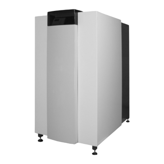
Konstruktion Produktbeschreibung Funktionsbeschreibung Der R600 Heizkessel beinhaltet nach- folgende Hauptkomponenten: Kesselverkleidung Frontabdeckung Höhenverstellbare Füße Schaltfeld Abgasanschluss Luftzufuhranschluss (unter Verkleidung) Gasanschluss Vorlauf Anschluss Rücklauf Anschluss 10 10 HT Rücklauf Anschluss (bei Bypasssystem), Zubehör 11 Befüll-/Entleerhahn 12 Öffnung für Elektrokabel 13 Tragkonstruktion 14 Brenner/1. -
Seite 44: Technische Daten
Technische Daten R601 R602 R603 R604 R605 R606 R607 Nennwärmeleistung 80/60ºC max/min * 142.1/24.0 190.1/40.6 237.2/40.6 285.2/40.6 384.5/79.6 480.6/79.6 545.1/79.6 Nennwärmeleistung 75/60ºC max/min * 142.2/24.0 190.3/40.6 237.4/40.6 285.5/40.6 384.9/79.7 481.1/79.7 545.6/79.7 Nennwärmeleistung 40/30ºC max/min * 150.4/25.5 201.2/43.1 251.0/43.1 301.8/43.1 402.4/83.6 502.9/83.6 570.4/83.6 Feuerungswärmeleistung max/min *... - Seite 45 Technische Daten R601 R602 R603 R604 R605 R606 R607 Öffnung für Elektrokabel 1105 1260 1470 1220 1435 1585 1735 Gasanschluss Vorlauf Anschluss 127.5 127.5 137.5 137.5 187.5 187.5 187.5 Rücklauf Anschluss Luftzufuhranschluss 1480 1480 1500 1500 1500 1500 1500 (unter Verkleidung)
-
Seite 46: Lieferumfang
R601); fängliche Systemlösung zusammenstel- • 2. (HT) Rücklaufanschluss für Split len. Für Details und Preise wenden sie System Anwendung; sich an den Elco Vertrieb. • Kontrollierter Bypass (inkl. Pumpe) inkl. Anschlusskit; • Plattenwärmetauscher (dT=10K/15K oder dT=20K) inkl. Anschlusskit;... - Seite 47 Der R600 ist ein vollausgerüstetes Kompaktheizgerät, welches voreinge- stellt und geprüft ist. Die maximale Breite beträgt 670mm für Modelle R601-R603 und 770mm für Modelle R604-R607. Somit ist es mög- lich alle Modelle durch eine normale Tür in einem Stück zu transportieren.
-
Seite 48: Demontage Verkleidung
Installation Demontage Verkleidung Vor Transport des Kessels die Ab- deckungen demontieren um Beschädi- gungen der Kesselverkleidung zu vermeiden. Die Demontage der Abdeckungen er- folgt wie auf den Fotos dargestellt:... - Seite 49 Installation Installation Installation Der Kessel sollte in einem frostschutz- sicheren Raum aufgestellt werden. Wird der Kessel im Dachboden aufge- stellt, darf dieser nicht der höchste Punkt der Installation sein. Bitte beachten Sie die empfohlenen Abstände gemäss nebenstehender Skizze beim Aufstellen des Kessels. Bei kleineren Abständen werden die Wartungsarbeiten erschwert.
-
Seite 50: Anschlüsse
Installation Anschlüsse Anschlüsse Hydraulische Anschlüsse Nachfolgendes Kapitel beschreibt wie Der R600 muss so in das System ein- die verschiedenen Anschlüsse an den gebunden werden, dass eine dauerhaf- Kessel vorzunehmen sind: te Wasserzirkulation (Zwangsumlauf- • prinzip) zu jeder Zeit gewährleistet ist. Hydraulische Anschlüsse Schließe den Vorlauf (4) und den •... - Seite 51 Installation Anschlüsse Gas Anschluss (1) Beachten sie folgende Empfehlungen: Der Gasanschluss erfolgt durch eine • Verwenden sie nur korrosionsbestän- ausgewiesene Fachkraft. Auch hier diges Material gelten die nationalen und lokalen • Der Durchmesser muss berechnet Normen und Vorschriften. und gemäß den nationalen Vorschrif- ten ausgewählt werden Schließe die Gasleitung leckfrei an den •...
-
Seite 52: Schaltplan - Kessel
Installation Schaltplan - Kessel Rücklauf- Vorlauf- Fühler Fühler... - Seite 53 Installation Schaltplan - Kessel Abgasfühler Anschluss verriegelnd...
-
Seite 54: Schaltplan - Zubehör
Installation Schaltplan - Zubehör Vorlauffühler Mischerantrieb (0.5A max.) Heizkreispumpe (2A max.) Vorlauffühler Mischerantrieb (0.5A max.) Heizkreispumpe (2A max.) - Seite 55 Installation Schaltplan - Zubehör * Brücke entfällt beim Anschluss des Gerätes Max. Wasser- Max. Wasser- Max. Gas- Kesseltemperatur druckwächter druckwächter druckwächter Dichtheits- kontrollgerät Gasventile...
-
Seite 56: Wasser- Und Hydrauliksystem
Inbetriebnahme Wasser– und Hydrauliksystem Der Kessel wird ausschließlich von In diesem Kapitel wird die Inbetriebnah- befugtem Personal in Betrieb genom- me des Kessels mit einer Standardkes- men. Die Garantie erlischt bei Nichtein- selsteuerung beschrieben. Sollte eine haltung dieser Bedingung. Zur Inbe- zweite Systemsteuerung installiert sein, triebnahme ist ein Protokoll auszufül- beachten Sie bitte das entsprechende... -
Seite 57: Gasversorgung
Inbetriebnahme Gasversorgung Kondensatanschluss Abgas- und Zuluftanschlüsse Gasversorgung Prüfen Sie den Anschluss zur Gasver- sorgung zum Kessel auf Dichtheit. Evtl. Lecks sind abzudichten, bevor der Kes- sel gestartet wird. Entlüften Sie Gasleitung und Gasventil. Dies erfolgt an der Messstelle (1) am Gasdruckwächter. -
Seite 58: Vorbereitung Für 1. Inbetriebnahme
Inbetriebnahme Vorbereitung für 1. Inbetriebnahme Vorbereitung für 1. Inbetriebnahme Legende: Ein/Aus Schalter • Öffnen Sie den Gasanschluss; Rücksprungtaste (ESC) • Betätigen Sie den Netztrennschalter, Raumtemperatur- Regulierknopf um den Kessel mit Strom zu versor- Bestätigungstaste (OK) gen; Handbetrieb- Funktionstaste • Schornsteinfeger-Funktionstaste Schalten Sie den Kessel mit dem Ein- Infotaste /Ausschalter (A) ein;... -
Seite 59: Verbrennungswerte
Verbrennungseinstellungen für Verbrennungswerte bei Volllast Erdgas G20 / G25 Starten Sie den Kessel in Reglerstopp- funktion unter Teillast 50%. Wenn der R601-R607 Kessel auf 50 % arbeitet, warten Sie 10.2 ± 0.2 2, max drei Minuten, sodass der Kessel die Verbrennung stabilisieren kann. -
Seite 60: Prüfung Wasserdurchsatz
Durchsatz kann nach der folgenden Formel (siehe unten stehen- de Tabelle für Nenndaten) berechnet werden: = √(∆p / ∆p ) * q tatsächlich Gemessen Nenn Nenn Wasser Durchsatz Daten R601 R602 R603 R604 R605 R606 R607 Nenndurchsatz 10.2 12.2 16.3 20.4 23.1... -
Seite 61: Sicherheitseinrichtungen Prüfen
Inbetriebnahme Funktion der Sicherheitseinrichtungen prüfen Gasdichtheitsprüfung Kessel außer Betrieb setzen Funktion der Sicherheitseinrichtun- Ionisationselektrode (6) gen prüfen Entfernen Sie die elektrische Steckver- Alle Sicherheitseinrichtungen sind auf bindung von der Ionisationselektrode, korrekte Funktion zu prüfen. Zu den während der Kessel läuft. Der Kessel Sicherheitseinrichtungen an Standard- schaltet ab (Nr. -
Seite 62: Inbetriebnahme Protokoll
Inbetriebnahme Inbetriebnahme-Protokoll Inbetriebnahme-Protokoll R600 Projekt Kesseltyp Projekt Seriennummer Adresse Jahr Nennwärmebelastung (Hi) [kW] Datum Nennwärmeleistung (Hi) [kW] Ingenieur System Wasserdruck [bar] Anlage: Dachgeschoss Wasser pH Erdgeschoss Wasserhärte [dºH] Keller Wasserchlorid [mg/l] Andere: ......Wasser-∆T Volllast [ºC] Hydraulik: Weiche Wasser-∆p [kPa] Beschichteter Wärmetauscher Kessel Wasserdurchsatz... -
Seite 63: Bedienung
Bedienung Bedienelemente Legende: Ein/Aus Schalter Rücksprungtaste (ESC) Raumtemperatur- Regulierknopf Bestätigungstaste (OK) Handbetrieb- Funktionstaste Schornsteinfeger-Funktionstaste Infotaste Reset Taste Betriebsarttaste Heizkreis(e) Display Betriebsarttaste Trinkwasser Entlüftungsfunktion (E) Betriebsarttaste Trinkwasser (M) Bestätigungstaste OK (D) Wird die Handtaste länger als 3 Sek. Zum Einschalten der Trinkwasser- Rücksprungtaste ESC (B) bereitung. -
Seite 64: Beschreibung Display Programmierung
Bedienung Beschreibung Display Programmierung Trinkwasserbetrieb wählen Heizbetrieb wählen (Reglerstopfunktion bei Tastendruck > 3 sek.) Display Info Taste Bestätigen Menü verlassen Handbetrieb (Entlüftungsfunktion bei Tasten- Reset druck > 3 sek.) Schornsteinfegerbetrieb Auswählen (Rechts- / Linksdrehung) Programmierung Endbenutzer Inbetriebsetzung Fachmann gewünschtes Menü gewünschte Benutzer-Ebene auswählen auswählen mit Taste OK bestätigen... -
Seite 65: Kurzübersicht Über Die Hauptfunktionen
Bedienung = Bestätigung = Abbruch bzw. zurück zur Kurzübersicht über die Hauptfunktionen Grundanzeige Taste Aktion Vorgehensweise Anzeige / Funktion HK2 gemeinsam mit HK1 Drehknopf links/rechts betätigen Komfortsollwert mit blinkender Temperatur -Angabe gewünschte Raumtempe- Drehknopf erneut drehen blinkende Temperaturanzeige in 0,5 °C-Schritten von 10,0—30 °C ratur einstellen Abspeichern mit Taste OK oder 5 sec. -
Seite 66: Wartung
Wartung Checkliste Ersetzen der Elektroden Der Kessel darf nur von befugtem Per- Checkliste sonal gewartet werden. Folgenden Maßnahmen sind durchzu- führen: Um den korrekten und sicheren Betrieb des Kessels sicherzustellen, sollte die- • Austausch der Zünd- und Ionisations- ser mindestens einmal jährlich über- elektroden;... -
Seite 67: Reinigung Der Kondensatwanne
Wartung Reinigung der Kondensatwanne Reinigen und Auffüllen des Siphons Inspektion der Verbrennungskammer Reinigung der Kondensatwanne • Entfernen Sie den Stopfen vom Ab- gastemperatursensor (1); • Entfernen Sie das innen liegende Abgasrohr (2) des Kessels, um die Kondensatwanne erreichen zu kön- nen;... -
Seite 68: Wasserdruck Und -Qualität
Wartung Wasserdruck und -qualität Verbrennungswerte Gasdichtheitsprüfung Prüfen Sie, ob Wasserdruck und - Prüfen Sie den Verbrennungsvorgang Prüfen Sie alle Dichtverbindungen mit qualität die Anforderungen erfüllen. unter Volllast und Mindestlast und korri- einem zugelassenen Seifen- oder elekt- Eingehende Informationen finden Sie gieren Sie ggf. -
Seite 69: Wartungsprotokoll
Wartung Wartungs-Protokoll Wartungs-Protokoll R600 Projekt Kesseltyp Projekt Seriennummer Adresse Jahr Nennwärmebelastung (Hi) [kW] Datum Nennwärmeleistung (Hi) [kW] Ingenieur System Wasserdruck [bar] Wasser pH Wasserhärte [dºH] Wasserchlorid [mg/l] Wasser-∆T Volllast [ºC] Wasser-∆p [kPa] Kessel Wasserdurchsatz Pumpeneinstellung Sicherheitseinrichtungen [ºC] Vorlauffühler geprüft [ºC] Abgasfühler geprüft Min.-Gasdruckschalter Einstell. - Seite 70 Störungen Im Falle einer Abschaltung erscheint ein Warnzeichen ( ) und ein blinkender Fehlercode auf dem Display. Die Störungsur- sache muss behoben werden, bevor man den Kessel R600 zurücksetzen kann. Die beigefügte Liste zeigt mögliche Abschal- tungen mit Hinweisen auf die Störungsursache. Fehler Fehler Beschreibung Code...
- Seite 71 Störungen Fehler Fehler Beschreibung Code Interner Fehler Parametrierungsfehler Gerät manuell verriegelt Gebläsefehler Luftdruckwächterfehler schließt nicht Fehler Heizkreis-FlowSwitch Luftdruckwächterfehler öffnet nicht Alarmkontakt H1 oder H4 aktiv Alarmkontakt H2 (EM1, EM2 oder EM3) oder H5 aktiv Alarmkontakt H6 aktiv Alarmkontakt H3 oder H7 aktiv Temperaturwächter Heizkreis 1 Temperaturwächter Heizkreis 2 Gerät im Parametriermoduls...
- Seite 72 Störungen Fehler Fehler Beschreibung Code Pufferrücklaufventil Y15 fehlt Pufferspeicher Adressfehler Vorregler / Zubringerpumpe Adressfehler Hydraulische Weiche Adressfehler Schienenvorlauffühler B10 fehlt Vorlauftemperatur 3 (Heizkreis 3) Überwachung Temperaturwächter Heizkreis 3 Erweiterungsmodul 3 Fehler (Sammelfehler) Repetitionszähler interner Fehler abgelaufen Repetitionszähler Fremdlicht abgelaufen Repetitionszähler Flammenausfall im Betrieb abgelaufen Repetitionszähler keine Flamme während Sicherheitszeit abgelaufen Repetitionszähler Gebläsefehler abgelaufen Keine Repetition zugelassen...
- Seite 73 Fühlerkennwerte In den nebenstehenden Diagrammen NTC 10kΩ Temperatursensor sind die Sensorwerte für alle Kessel- (Vorlauf-, Rücklauf-, Abgas-, Brauchwasser– und Weichefühler) sensoren und in den Zubehörsätzen enthaltenen, optionalen Sensoren an- gegeben. Die Diagramme zeigen Durchschnittswerte, da alle Sensoren 60000 Schwankungen unterliegen. 55000 Bei der Messung der Widerstandswerte 50000...
-
Seite 74: Konformitätserklärung
Konformitätserklärung Konformitätserklärung Rendamax BV, Hamstraat 76, 6465 AG Kerkrade (NL), erklärt, dass das Produkt R600 Mit folgenden Normen übereinstimmt: EN 298 EN 656 EN 15420 EN 55014-1 / -2 EN 61000-3-2 /-3 EN 60 335-1/ -2 Gemäss den Bestimmungen der Richtlinien: 92 / 42 / EWG (boiler efficiency directive) 2009 / 142 / EWG (gas appliance directive) 2006 / 95 / EWG (low voltage directive)