Herunterladen Inhalt Inhalt Diese Seite drucken

Werbung

Verfügbare Sprachen

Verfügbare Sprachen

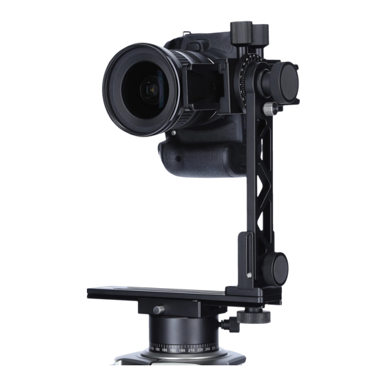
Panoramakopf 200 Mark II
Panoramic Head 200 Mark II
360°
Panorama-
Aufnahmen
360°
panoramic
images
User Guide
for German and English
www.rollei.de

Werbung

Kapitel

Inhaltsverzeichnis
loading

Inhaltszusammenfassung für Rollei 200 Mark II

  • Seite 1 Panoramakopf 200 Mark II Panoramic Head 200 Mark II 360° Panorama- Aufnahmen 360° panoramic images User Guide for German and English www.rollei.de...
  • Seite 2: Inhaltsverzeichnis

    Inhaltsverzeichnis Einführung . . . . . . . . . . . . . . . . . . . . . . . . . . . . . . . . . . . . . . . . . . . . . . 3 Hauptmerkmale | Verpackungsinhalt 1.
  • Seite 3: Hauptmerkmale

    Liebe Kundin, lieber Kunde, herzlichen Glückwunsch zum Kauf eines qualitativ hochwertigen Rollei Produktes . Sie haben sich für den Panoramakopf mit guter technischer Ausstattung ent- schieden, der sich besonders einfach bedienen lässt . Bitte lesen Sie alle Hinweise sorgfältig und aufmerksam . Beachten Sie besonders alle Sicherheitshinweise .
  • Seite 4: Sicherheitshinweise

    1. Sicherheitshinweise Gefahr für Kinder • Halten Sie Kinder von Verpackungsmaterial fern . Es besteht u .a . Erstickungsgefahr! Vorsicht – Sachschäden • Stellen Sie den Panoramakopf auf einen festen, ebenen Untergrund . • Schützen Sie das Gerät vor Nässe, Staub, hohen Temperaturen und direkter Sonneneinstrahlung .
  • Seite 5: Produktbeschreibung

    2. Produktbeschreibung Der Rollei Panoramakopf 200 Mark II ist ein Mehrzeilen-Panoramakopf . Er hat Gleitteller zum Aufsetzen der Kamera auf der Drehachse des Panoramakopfes, sowie eine Gleitplatte, die sich um die Achse herum nach vorn / nach hinten dreht . Diese Neigung ermöglicht es, die Kamera / das Objektiv vom „Nodal- punkt“...
  • Seite 6: Voraussetzungen Für Ein Gutes Panoramabild

    3. Voraussetzungen für ein gutes Panoramabild Der Panoramakopf wurde so entwickelt, dass er das Erstellen virtueller Szenen mit dem Computer über verschiedene Sequenzen von Digitalfotos oder digitalisierten Fotos ermöglicht, die von verschiedenen vertikalen Winkeln aus eingefangen werden . Für eine gute Panoramasequenz sind vier Grundvoraussetzungen erforderlich: 1 .
  • Seite 7: Den Panoramakopf Aufbauen

    4. Den Panoramakopf aufbauen Montieren Sie den Panoramakopf über das 3/8“ Gewinde an der Basisplatte Ihres Stativs . Entfernen Sie nun Knopf „A“ komplett (siehe 1 in Abb . 1) und drehen die Halterung in die vertikale Position (2) . Fixieren Sie die Halterung indem Sie die Schraube in das dafür vorgesehene Gewinde einschrauben .
  • Seite 8: Montage Der Kamera

    5. Montage der Kamera Abb . 2 Um die obere Schiene des Panorama- kopfes abzunehmen, lösen Sie zunächst die Fixierung „D“ (siehe 1 in Abb . 2) . Ziehen Sie die Schiene bis zum Anschlag heraus und drücken dann den Sicherungsknopf „E“ (2), um sie ganz zu entfernen (3) .
  • Seite 9 5. Montage der Kamera Abb . 4 In der Schnellwechselplatte befindet sich eine 1/4“-Schraube, die zum Be festigen der Kamera dient (siehe Abb . 4) . Montieren Sie nun die Kamera mit der Befes- tigungsplatte auf der Gleitschiene wie in Abb . 5 dargestellt .
  • Seite 10 5. Montage der Kamera Die mit den Platten verbundene Kamera setzen Sie nun mit dem Objektiv nach unten in den Panoramakopf ein (siehe Abb . 6) . Schieben Sie die Gleitschiene über den Widerstand der Sicherheitsverriegelung hinweg in die gewünschte Position und fixieren sie die Schiene durch die seitliche Schraube .
  • Seite 11: Positionierung Des Nodalpunktes

    6. Positionierung des Nodalpunktes Um die optische Achse „Q“ der Kamera (siehe Abb . 8) zur Panorama-Drehachse „R“ im Stativ-Mittelpunkt (center) auszurichten, lösen Sie die Schraube der Skalenschiene „S“, bringen die Kamera in die entsprechende Position und fixieren die Schraube wieder . Abb .
  • Seite 12: Längspositionierung

    6. Positionierung des Nodalpunktes 6.1 Längspositionierung Wählen Sie eine Ebene, die ein nahes Objekt „1” und ein fernes Objekt „2” enthält, die sich aber in der gleichen Sichtausrichtung in vertikaler Richtung befinden (Abb . 10) . 1 . Lösen Sie Knopf „W“ und drehen die Kamera vertikal, so dass die beiden Objekte „1“...
  • Seite 13: Seitliche Positionierung

    6. Positionierung des Nodalpunktes 6.2 Seitliche Positionierung Wählen Sie eine Ebene, die ein nahes Objekt „1” und ein fernes Objekt „2” in der gleichen Sichtausrichtung in horizontaler Richtung enthält (Abb . 13) . 1 . Lösen Sie die Fixierung der Basis (Lock), um die Kamera um die Panoramaachse herum zu bewegen .
  • Seite 14: Anleitung Für Die Kugelpanoramafotografie

    7. Anleitung für die Kugelpanoramafotografie Ein besonderes Bild erhält man durch Verknüpfen verschiedener, in unter- schiedlichen horizontalen Winkeln aufgenommener Panoramasequenzen . Zuerst ist die Anzahl der Sequenzen zu definieren, die zum Komplettieren der Kugel notwendig sind . Diese Anzahl hängt von dem verwendeten Linsen- winkel in Verbindung mit der Änderung des Kopfes (Wahl von Schritten von 15°/24°/60°...
  • Seite 15 7. Anleitung für die Kugelpanoramafotografie Legen Sie die Anzahl der Aufnahmen oder Drehschritte (15°/ 24°/6 0° o der 90°) zwischen jeder Auslösung für die erste Panoramasequenz fest (siehe Tabelle) . Winkel 90° 60° 45° 36° 30° 24° 20° 15° 10° 5° Anz.
  • Seite 16: Entsorgung

    8. Entsorgung 8.1 Verpackung Die Produktverpackung besteht aus recyclingfähigen Materialien und kann dem Wertstoffkreislauf zugeführt werden . Entsorgen Sie diese umweltgerecht . 8.2 Gerät Wenn das Gerät einmal ausgedient hat, muss das Gerät entsprechend EG-Richtlinie 2002/96/EG einer geordneten Entsorgung zugeführt werden und darf keinesfalls über den normalen Hausmüll entsorgt werden .
  • Seite 17: Spezifikationen

    9. Spezifikationen Technische Daten Gewicht 1171 g Material Aluminium Stativkopf-Steuerung 360° Rastschritte Rotation 4x90° | 6x60° | 15x24° | 24x15° Max. Traglast 3 kg Maße (zusammengeklappt) 22 x 14 x 8,7 cm Kameraanschluss 1/4“ Schraubengewinde Stativanschluss 3/8“ Gewinde Lieferumfang Panoramakopf, Transportkoffer Änderungen von Design und technischen Daten bleiben vorbehalten und bedürfen keiner Ankündigung .
  • Seite 18 Table of Contents Introduction . . . . . . . . . . . . . . . . . . . . . . . . . . . . . . . . . . . . . . . . . . . . 19 Key Features | Package Contents 1.
  • Seite 19: Key Features

    Dear Customer, Congratulation on purchasing a high quality Rollei product .You have opted for the panorama head with great technical equipment, which is particularly simple to operate . Please read all the instructions carefully and thouroughly . Pay particular attention to all safety instructions .
  • Seite 20: Safety Instructions

    1. Safety instructions Danger for children • Keep children away from packaging risks include danger of suffocation! Caution – damage to property • Place the panorama head on a firm, level surface . • Protect the device from moisture, dust, high temperatures and direct sunlight .
  • Seite 21: Product Description

    2. Product description The Rollei Panoramic Head 200 Mark II is a multi-row panorama head . It has a sliding plate for placing the camera on the rotating axis of the panorama head and a sliding plate which rotates backwards and forwards around the axis .
  • Seite 22: Requirements For A Good Panoramic Picture

    3. Requirements for a good panoramic image The panorama head was developed to enable the creation of virtual scenes with a computer by means of various sequences of digital photos or digitised photos, which are captured from various vertical angles . For a good panoramic sequence, four basic requirements are necessary: 1 .
  • Seite 23: Assembly Of The Panorama Head

    4. Assembly of the panorama head Attach the panoramic head onto the base plate of your tripod by using the 3/8“ thread . Now completely remove knob ”A“ (see 1 in Fig . 1) and rotate the bracket into the vertical position (2) . Secure the bracket by screwing the knob into the thread .
  • Seite 24: Mounting The Camera

    5. Mounting the camera Fig . 2 To remove the upper rail of the panorama head, first loosen the fixing knob “D” (see1 in Fig . 2) . Pull the rail out until it stops and then push the locking button “E” (2) to remove it completely (3) .
  • Seite 25 5. Mounting the camera Fig . 4 The quick release plate has a 1/4“ screw to attach it to the camera (see Fig .4) . Now attach the camera with the mounting plate onto the slide rail as shown in Fig . 5 . Make sure that the centre of the lens is lined up with centre of the plate .
  • Seite 26 5. Mounting the camera Now place the camera attached to the plates into panorama head with the lens pointing downwards (see Fig . 6) . Push the slide rail past the resistance of the saftey lock into the desired positions and secure the rail using the screw the side .
  • Seite 27: Positioning Of The Nodal Point

    6. Positioning of the nodal point In order to algin the camera´s optical axis ”Q“ in relation to the panorama rotating axis ”R“ in the tripod´s centre, loosen the screw on scale rail ”S“, move the camera into the appropriate position and retighten the screw . Fig .
  • Seite 28: Longitudinal Positioning

    6. Positioning of the nodal point 6.1 Longitudinal positioning Select plane that contains a near object ”1“ and a distant object ”2“ wich are also situated in the same visual orientation in a vertical direction (Fig .10) . 1 . Loosen knob ”W“ and rotate the camera vertically so that both objects ”1“ and ”2“...
  • Seite 29: Lateral Positioning

    6. Positioning of the nodal point 6.2 Lateral positioning Select a plane that contains a near object ”1“ and a distant object ”2“ in the same visual orientation, in a horizontal direction (Fig . 13) . 1 . Loosen the base fixture (lock) in order to move the camera about the panoramic axis .
  • Seite 30: Instructions For Spherical Panoramic Photography

    7. Instructions for spherical panorama photography A special image can be achieved by combining various panorama sequences taken at different horizontal angles . First of all number of sequences necessary to complete the sphere must be defined . This number depends on the lens angle used in conjunction with the adjustment of the head (choice of 15°/24°/60°...
  • Seite 31 7. Instructions for spherical panorama photography Set the number of shots or rotary steps (15°, 24°, 60° or 90°) between each shutter for the first panorama sequence (see table below) . Angle 90° 60° 45° 36° 30° 24° 20° 15° 10° 5° No.
  • Seite 32: Disposal

    8. Disposal 8.1 Packaging The product packaging is made from recycable materials and can be ureturned to the resource cycle . Dispose of it in an environmentally friendly way . 8.2 Device When the device has eventually worn out it must be disposed of properly according to EC directive 2002/96/EC and must under no circumstances be disposed of with normal household waste .
  • Seite 33: Specifications

    9. Specifications Technical Features Weight 1171 g Material Aluminum Panoramic head control 360° Rotation steps 4x90° | 6x60° | 15x24° | 24x15° Max. load 3 kg Size (folded) 22 x 14 x 8 .7 cm Camera connection 1/4“ screw Tripod connection 3/8“...
  • Seite 34 Panoramakopf 200 Mark II Panoramic Head 200 Mark II www.rollei.com...
  • Seite 35 ARCA SWISS kompatibel / compatible...
  • Seite 36: Service-Hotline

    Distribution Rollei GmbH & Co. KG In de Tarpen 42 D-22848 Norderstedt Service Hotline +49 40 270750270 Return Service: Rollei Service Germany Denisstraße 28a 67663 Kaiserslautern www.rollei.de/social www.rollei.com/social www.rollei.com...

Inhaltsverzeichnis