Ripmax NANO Boomerang Bauanleitung
Inhaltsverzeichnis
Quicklinks
Specification:
Wingspan: 1520mm (59.8")
Length: 1700mm (67")
Flying weight: 6-6.5kg (13.2-14.3lbs)
Radio: 6+ Channel* Servos: 9x*
*
(Recommendation, not included)
Technische Daten:
Spannweite: 1520mm
Länge: 1700mm
Fluggewicht: ca. 6-6.5kg
Fernsteuerung: 6+-Kanal* Servos: 9x*
*
(empfohlen aber nicht enthalten)
Instruction Manual
Bauanleitung
Inhaltsverzeichnis

Verwandte Anleitungen für Ripmax NANO Boomerang


Inhaltszusammenfassung für Ripmax NANO Boomerang
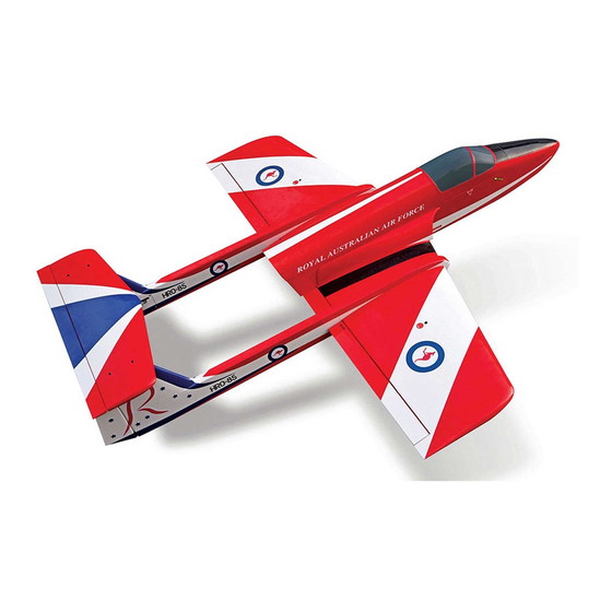
- Seite 1 Instruction Manual Bauanleitung Specification: Technische Daten: Wingspan: 1520mm (59.8”) Spannweite: 1520mm Length: 1700mm (67”) Länge: 1700mm Flying weight: 6-6.5kg (13.2-14.3lbs) Fluggewicht: ca. 6-6.5kg Radio: 6+ Channel* Servos: 9x* Fernsteuerung: 6+-Kanal* Servos: 9x* (Recommendation, not included) (empfohlen aber nicht enthalten)
-
Seite 2: General Notices
Ripmax shall not be liable for any loss, consequential loss, damage will increase the risk of injury. Always keep yourself at a or expense arising from the improper use or operation in anyway. -
Seite 3: Wichtige Hinweise
Haftungsausschluss: mit sich drehenden Teilen in Berührung kommen! Denken Sie auch an Ihre Haustiere! Ripmax Produkte sind häufig nur ein Teil einer ganzen Funktionskette. Diese Funktionskette, wie auch die Einhaltung der Montage und Betriebsanleitung als auch die Bedingungen und Fliegen Sie grundsätzlich, ob mit Modellflugzeugen-, Hubschraubern- oder Multicoptern, nie in Augenhöhe... -
Seite 4: Parts List
INSTRUCTIONS / ANLEITUNG Contents / Inhalt Parts List: Take a moment to identify each of the par ts supplied and read through Wings. these instructions before commencing assembly. Fuselage. Tailplane. Centre section. Canopy. Booms x 2. Air intakes x 2. Radio tray. -
Seite 5: Required To Complete / Erfor Der Liches Zubehör
INSTRUCTIONS / ANLEITUNG Congratulations on your purchase of the Boomerang Nano. This performance model is ideal for use as a first jet or as a sports jet model. Before you build the model, please read the instructions the whole way through to understand the construction sequence. Warning: The Boomerang Nano has been designed to enable turbines of 44 to 70 Newtons thrust to be installed, however it is VERY important to note that if turbines of over 60 Newtons thrust are fitted, full power should not be used for any extended diving manoeuvres, as this will lead to speed in excess of the design specifications. - Seite 6 INSTRUCTIONS / ANLEITUNG Stage Schritt The wings and ailerons are supplied with the hinges loose fitted, ready for installation. Remove both ailerons and ensure that the hinges are inserted mid-way in their slots. Using thin cyano, pour a drop onto each hinge – above and below – ensuring the glue soaks into the hinge and surrounding wood on both ailerons.
- Seite 7 INSTRUCTIONS / ANLEITUNG Stage Schritt Feed the servo lead through the wing by tying one end of the lead to the pre-installed string in the wing structure. A piece of tape on the plug and string helps keep the plug straight and makes it easier to feed through the wing ribs.
- Seite 8 INSTRUCTIONS / ANLEITUNG Stage Schritt The tailplane and elevator are supplied with the hinges loose fitted, ready for installation. Remove the elevator and ensure that the hinges are inserted mid-way in their slots. Using thin cyano, pour a drop onto each hinge – above and below – ensuring the glue soaks into the hinge and surrounding wood on the elevator.
- Seite 9 INSTRUCTIONS / ANLEITUNG Stage Schritt Install the elevator servo to the mounting plate as shown, and then fit a suitable extension lead, long enough to reach the exit for the boom on one side. Secure the leads together using a short section of heat shrink, tape or a lead lock. Centre the servo and fit the servo arm.
- Seite 10 INSTRUCTIONS / ANLEITUNG Stage Schritt Locate the wing centre panel apertures for the flap and undercarriage under the covering on the underside of the wing centre panel. Carefully trim away the covering as shown. (Top Tip) With thin cyano glue, pour a small amount around the wheel wells in the balsa, where the covering meets the balsa sheet, this will seal the wood and stop the covering from lifting.
- Seite 11 INSTRUCTIONS / ANLEITUNG Stage Schritt Install the flap servo to the mounting plate as shown, and then fit a suitable extension lead, long enough to reach the exit for the boom on one side. Secure the leads together using a short section of heat shrink, tape or a lead lock.
- Seite 12 INSTRUCTIONS / ANLEITUNG Stage Schritt Fit the control horn to the flap and then assemble the flap pushrod as shown, making sure that keepers are fitted to the clevises for security. Befestigen Sie am Klappengestänge ein paar Gabelköpfe und Sicherungsschrauben. Mit etwas Kraftstoffschlauch über den Gabelköpfen, werden diese zusätzlich gesichert.
- Seite 13 INSTRUCTIONS / ANLEITUNG Stage Schritt Carefully push the rudder into position, ensuring a gap-free hinge line. Make sure that the rudder lines up with the boom at the bottom and that it is free to move through its entire travel. Minimise any hinge gap, then carefully add a couple of drops of thin cyano to the top and bottom of each hinge ensuring that the glue does not run through the hinge line on the bottom of the...
- Seite 14 INSTRUCTIONS / ANLEITUNG Stage Schritt Fit the controls horn to the rudder and then assemble the rudder pushrod as shown, making sure that keepers are fitted to the clevises for security. Now repeat stages 24-29 for the other boom. Befestigen Sie am Seitenrudergestänge ein paar Gabelköpfe und Sicherungsschrauben.
- Seite 15 INSTRUCTIONS / ANLEITUNG Stage Schritt Fit the airlines to the retract units making sure that the coloured air tubing match each other and the brake air lines are fitted at the same time. Be sure that the air tubing is long enough to reach the centre exit holes in the wing centre panel and down to the radio tray.
- Seite 16 INSTRUCTIONS / ANLEITUNG Stage Schritt Locate the fuselage aperture for the nose undercarriage under the covering on the underside of the fuselage. Carefully trim away the covering as shown. (Top Tip) With thin cyano glue, pour a small amount around the wheel aperture in the balsa, where the covering meets the balsa sheet, this will seal the wood and stop the covering from lifting.
- Seite 17 INSTRUCTIONS / ANLEITUNG Stage Schritt Refit the retract units into the fuselage, making sure that the air tubing is free and not crimped or crushed, then drill a hole on one side just below the servo and run the air tubing to the radio tray at the back.
- Seite 18 INSTRUCTIONS / ANLEITUNG Stage Schritt Locate the front nose wheel cover, cut an aperture to suit the retract leg and screw in place as shown. Schneiden Sie die Öffnung aus der vorderen Fahrwerksabdeck- ung aus und befestigen Sie diese wie gezeigt. Stage Schritt Locate the plastic wing dowels and using epoxy glue these into...
- Seite 19 INSTRUCTIONS / ANLEITUNG Stage Schritt Cut away the covering from the face of the fuselage to wing joint as shown. Schneiden Sie nun auch entsprechend die Folie am Rumpf ab und entfernen Sie diese. Stage Schritt With thirty minute epoxy, glue the centre wing panel to the fuselage and replace the wing bolts, making sure that the wing centre panel is square and seated onto the fuselage, wipe any excess epoxy from the model before it cures using methylated...
- Seite 20 INSTRUCTIONS / ANLEITUNG Stage Schritt Remove water-soluble pen marks using methylated spirit or methanol, then using sandpaper rough the inside of the fibreglass air intakes on the glue line, using slow thirty minute epoxy, glue the fibreglass air intakes to the fuselage using masking tape to hold in position.
- Seite 21 INSTRUCTIONS / ANLEITUNG Stage Schritt Locate the bolt holes under the covering on the tailplane front and rear for mounting to the booms, carefully trim away the covering as shown. Schneiden Sie vorsichtig die Öffnungen für die Befestigung des Höhenleitwerkes aus. Stage Schritt Bolt on the tailplane using the bolts supplied, making sure to fit...
- Seite 22 INSTRUCTIONS / ANLEITUNG Stage Schritt The wing panels are retained using the pre-installed moulded clamps onto the wing joiner ends. Secure the wings in place using a machine screw through the spar clamp in the topside of the wing. Sichern Sie nun die Flächen mit den Schrauben auf der Ober- seite der Flächen.
- Seite 23 INSTRUCTIONS / ANLEITUNG Stage Schritt At this stage we took the opportunity to paint the inside of the fuselage and radio tray with stone effect paint and lacquer, this protects the wood work from fuel spills and looks great. In diesem Schritt können Sie die Gelegenheit nutzen und den Rumpf innen mit einer Lackierung versehen, welche die Teile vor Kraftstoffspritzern schützt und eine optische Aufwertung darstellt.
- Seite 24 INSTRUCTIONS / ANLEITUNG Stage Schritt Install the receiver and switch on the radio/equipment plate using double sided tape for the receiver and neaten the wiring using cable ties under the plate, then screw the plate to the fuselage. Befestigen Sie nun den Empfänger und den Schalter, wie gezeigt, und schließen Sie die Servokabel entsprechend an.
- Seite 25 INSTRUCTIONS / ANLEITUNG Stage Schritt Fit the fuel tank and retain with a small amount of servo tape onto the mounting plates and two heavy duty cable ties – tighten these snugly, but do not overtighten, as the fuel tank may be damaged.
- Seite 26 INSTRUCTIONS / ANLEITUNG Completed Model / Fer tiges Modell With the model completed it is vital to go through thorough checks of every part, as it is all too easy to forget to do up a screw tightly, or neglect to safety wire fuel tubing. Any jet requires very careful assembly and maintenance if it is to be safe and reliable, and the Nano deserves this care and attention.
-
Seite 27: Apply Decals / Anwenden Von Decals
INSTRUCTIONS / ANLEITUNG Apply Decals / Anwenden von Decals You are now ready to apply the supplied decals. One at a time, carefully remove the decals from their backing sheet, apply to the model and gently smooth down. Entfernen Sie die Aufkleber nacheinander vorsichtig von der Trägerfolie und bringen Sie diese an den gewünschten Stellen an. - Seite 28 INSTRUCTIONS / ANLEITUNG Control T hrows / Ruderausschläge For initial flights, we recommend the following control throws - each measured at the widest point of the surface. With experience these rates can be increased for high performance aerobatics. Für erste Flüge empfehlen wir die folgenden Ruderausschläge (gemessen am äußersten Ende der Ruder). Mit entsprechnder Erfahrung können diese Ruderausschläge vergrößert werden.
-
Seite 29: Pre-Flight Checks / Vorflug Checks
INSTRUCTIONS / ANLEITUNG Pre-Flight Checks / Vorflug Checks • Completely charge your transmitter and receiver batteries before flying. • Carefully check your model over to ensure that all screws are tight and everything is well bonded. • Double-check the Centre of Gravity. •... -
Seite 30: Flying The Nano / Den Nano Flie Gen
INSTRUCTIONS / ANLEITUNG Flying the Nano / Den Nano Flie gen We recommend the use of a long runway for first flights, particu- performed at a safe height, for example turns in both directions, larly if this is the first jet model you have flown. The Nano a good slow flight, a clean stall, etc, etc. -
Seite 31: Spare Par Ts / Ersatzteile
Turbinenleistung frühzeitig nachgeschoben werden. Spare Par ts / Ersatzteile Spare parts are available from all Ripmax stocked model shops. In case of any difficulty, any product queries, or to locate your local Ripmax stockist, please visit www.ripmax.com Ersatzteile sind in allen Ripmax-Modellläden erhältlich. Bei Problemen, Produktfragen oder zur Lokalisierung Ihres lokalen Ripmax-Händlers... - Seite 32 Copying or reproduction, even in parts require written schriftlicher Genehmigung der Ripmax Ltd. permission of Ripmax Ltd. Made in China Manufactured for and distributed to your local model shop by: Ripmax Ltd., 241 Green Street, Enfield, EN3 7SJ. United Kingdom.