Mahr Micromar 40 F Bedienungsanleitung
Feinzeiger-messschraube
Quicklinks
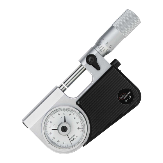
7. Beschreibung
DE
1
Abhebetaste
2
Messtrommel
3
Hülse
4
Messspindel
5
Toleranzmarken
6
Feststelleinrichtung
7
Bügel
8
Isolierplatten
9 Messflächen
10 Zeiger
11 Amboss
12 Schraubendreher
13 Stellschraube
14 Klemmschraube
15 Halter
16 Tisch
17 Klemmschraube für Tisch
18 Feinzeiger
19 Klemmung für Feinzeiger
13
10
11
9
4
6
3
2
5
0
45
7
1
8
5
12
40 F
8. Messen
a) Mit Messschraube als Referenz
–
Nennmaß mit Trommel 2 einstellen, gegebenenfalls
Toleranzgrenzen mit Toleranzmarken 5 einstellen.
–
Messspindel 4 mit Feststelleinrichtung 6 klemmen
–
Amboss 11 über Abhebetaste 1 abheben
–
Werkstück einführen
–
Amboss 11 durch Zurückfahren der Abhebetaste 1
auf Werkstück aufsetzen
–
Abweichung vom Nennmaß auf Zifferblatt ablesen.
b) Mit Einstellmeister als Referenz
–
Einstellmeister (z.B. Prüfstift, Endmaß) zwischen
Messspindel 9 und Amboss 11 bringen
–
Messspindel über Messtrommel 2 bewegen, bis
Zeiger 10 auf „Null" steht.
–
Messspindel 4 mit Feststelleinrichtung 6 klemmen,
gegebenenfalls Toleranzgrenzen mit Toleranzmarken
5 einstellen
–
Amboss 11 über Abhebetaste 1 abheben
–
Werkstück einführen
–
Amboss 11 durch Zurückfahren der Abhebetaste 1
auf Werkstück aufsetzen
–
Abweichung vom Nennmaß auf Zifferblatt ablesen.
c) Justierung der Nullstellung
– Messflächen reinigen
–
Spindel über Messtrommel 2 bewegen, bis Skalenli-
nie „0" der Trommel mit Bezugslinie übereinstimmt
–
Spindel 4 mit Feststelleinrichtung 6 klemmen
–
Stellschraube 13 mit Schraubendreher 12 verstellen,
bis Zeiger 10 auf „0" steht.
9. Erweiterung des Messbereichs bei
40 T >50 mm, 40 TS
–
Messschraube mit Trommel 2 auf „0,00 mm" bzw. auf
Anfang des Messbereichs stellen
–
Spindel 4 mit Feststelleinrichtung 6 klemmen
–
Klemmung 14 öffnen und Halter 15 nach links ver-
schieben
–
Einstellmaß z.B. 25 mm zwischen Messspindel 4 und
Amboss 11 bringen
–
Halter 15 verschieben, bis Amboss 11 an Messspin-
del 4 anliegt, dann mit Klemmschraube 14 klemmen
–
Feinzeiger 18 positionieren, bis Zeiger auf „Null"
steht, dann mit Klemmschraube 19 klemmen. Bei
anderen Anzeigegeräten auf Mitte der Messspanne
des Anzeigegeräts positionieren.
10. Pflege der Messschraube
–
Bügelmessschraube von Staub und Schmutz reini-
gen
–
Zum Reinigen des Spindelgewindes die Messspindel 4
herausschrauben
–
Gewinde mit Waschbenzin reinigen und ein
synthetisches Öl auftragen
–
Auf Messspindel 4 und Amboss 11 ein synthetisches
Öl auftragen.
7. Description
EN
1
Lifting device
2
Thimble
3
Sleeve
4
Measuring spindle
5
Tolerance markers
6
Locking device
7
Frame
8
Heat insulators
9
Measuring faces
10 Pointer
11 Anvil
12 Screwdriver
13 Adjustment scew
14 Locking screw (clamp) for the indicator holder
15 Holder
16 Base
17 Clamping screw for the base
18 Dial comparator
19 Locking screw
18
13
14
15
11
9
4
6
3
0
5
19
10
1
8
40 T
8. Measurement
a) Use the micrometer as a reference
–
Set the nominal value with the thimble 2, if necessary
set the tolerance limits with the tolerance markers 5
–
Secure the spindle 4 with locking device 6
–
Lift the anvil 11 with the lifting device 1
–
Insert the work piece
–
Lower the anvil 11 on to the workpiece by pressing in
the lifting device 1
–
Read off the deviation of the nominal value on the
dial face of the indicating instrument.
b) Using a setting master as a reference
–
Insert a setting master / standard (e.g. pin gage,
gage block) between the spindle 9 and the anvil 11
–
Turn the spindle with the thimble 2, until the pointer
10 is at „zero"
–
Secure the spindle 4 with locking device 6, if ne-
cessary set the tolerance limits with the tolerance
markers 5
–
Lift the anvil 11 with the lifting device 1
–
Insert the work piece
–
Lower the anvil 11 on to the workpiece by pressing in
the lifting device 1
–
Read off the deviation of the nominal value on the
dial face of the indicating instrument.
c) Adjusting / setting to zero
–
Clean measuring faces
–
Rotate the spindle with the thimble 2, until the refe-
rence line of the sleeve is aligned with the „0"-line of
the scale
–
Secure the spindle 4 with locking device 6
–
Adjust the setting screw 13 with the screwdriver 12,
until the pointer 10 is at „0".
9. Extending the measuring range with the
40 T >50 mm, 40 TS
–
Set the thimble 2 on the micrometer to either
„0,00 mm" and / or the beginning of the measuring
range
–
Clamp the measuring spindle 4 with the locking
device 6
–
Open the clamp 14 and turn the holder 15 to the left
–
Insert a setting standard e.g. 25 mm between the
spinlde 4 and the anvil 11
–
Turn the holder 15 until the anvil 11 is aligned with
the spindle 4, then fix into position with the locking
screw 14
–
Insert the dial comparator 18, until the pointer is at
„zero", then clamp in position with the locking screw
19. When using other indicating instruments positi-
on at the center of the span of measurement of the
particular indicating instrument.
10. Service of the Micrometer
–
Remove dust and dirt from the Micrometer
To clean the spindle thread unscrew the spindle 4
–
–
Clean the thread with petroleum ether followed by
the application of a trace of synthetic oil
–
Apply a trace of synthetic oil to spindle 4 and anvil 11
7. Description
FR
1
Touche de relevage
2
Barillet
3
Vernier
4
Vis micrométrique
5
Ergot de tolérance
6
Dispositif de blocage
7
Etrier
8
Plaques isolantes
9
Faces de mesure
10 Aiguille
11 Enclume
12 Tournevis
13 Vis de réglage
14 Vis de serrage
15 Fixation
16 Table
17 Vis de fixation sur table
18 Comparateur
19 Fixation du comparateur
18
13
2
5
5
0
45
19
10
1
7
40 TS
8. Mesure
a) avec la vis micrométrique comme référence
–
Régler la cote nominale avec le barillet 2 ; si néces-
saire, ajuster les tolérances min./max. à l'aide des
ergots marquant la tolérance 5
–
Serrer la vis micrométrique 4 avec le dispositif de
blocage 6
–
Relever l'enclume 11 avec la touche de relevage 1
–
Introduire la pièce
–
Poser l'enclume 11 sur la pièce par retrait de la tou-
che de relevage 1
–
Lire l'écart par rapport à la cote nominale sur le ver-
nier
b) avec l'aide de l'étalon comme référence
–
Mettre l'étalon (par exemple, câle étalon) entre la vis
de mesure 9 et l'enclume 11
–
Placer la vis de mesure au-dessus du barillet 2 de
sorte que l'aiguille 10 se place sur „zéro".
–
Serrer la vis micrométrique 4 à l'aide du dispositif de
blocage 6 ; si nécessaire, régler les limites min./max.
au moyen des ergots 5
–
Soulever l'enclume 11 avec la touche de relevage 1
–
Introduire la pièce
–
Poser l'enclume 11 sur la pièce par retrait de la tou-
che de relevage 1
–
Lire la différence par rapport à la côte nominale sur le
vernier
c) ajustage du zéro
–
Nettoyer les faces de mesure
–
Placer la vis au-dessus du barillet 2 jusqu'à ce que
son trait „0" soit à fleur de la ligne de référence
–
Serrer la vis micrométrique 4 avec le dispositif de
blocage 6
–
Ajuster la vis de réglage 13 au moyen du tournevis
12 jusqu'à ce que l'aiguille 10 soit sur „0".
9. Extension de l'étendue de mesure des
40 T >50 mm, 40 TS
Placer la vis micrométrique 2 sur „0,00 mm" ou sur le
–
début de l'étendue de mesure en utilisant le barillet
–
Serrer la vis micrométrique 4 au moyen du dispositif
de blocage 6
–
Ouvrir le blocage 14 et déplacer la fixation 15 vers la
gauche
–
Ajuster la cote de réglage (par exemple 25 mm) entre
la vis micrométrique 4 et l'enclume 11
– Déplacer la fixation 15 jusqu'à ce que l'enclume 11
se mette contre la vis micrométrique 4 puis serrer
avec la vis de serrage 14
–
Positionner le comparateur 18 de sorte que l'aiguille
se mette sur „zéro" puis bloquer avec la vis de ser-
rage 19. Pour les autres appareils, le positionner au
centre de l'étendue de mesure de l'appareil.
10. Entretien du micromètre
–
Eliminer toute trace de poussière ou la présence de
copeaux sur la vis micrométrique à étrier
–
Dévisser totalement la vis micrométrique 4 afin de
pouvoir nettoyer le filetage
–
Le nettoyage du filet devra se faire avec du pétrole ;
après nettoyage, appliquer une huile synthétique
–
Appliquer de l'huile synthétique sur la vis micromé-
trique 4 et sur l'enclume 11
7. Descrizione
IT
1
Tasto di sollevamento
2
Tamburo di misura
3
Bussola
4
Vite micrometrica
5
Indici di tolleranza
6
Dispositivo di bloccaggio
7
Archetto
8
Piastre isolanti
9 Superfici di misura
10 Indicatore
11 Incudine
12 Cacciavite
13 Vite di regolazione
14 Vite di bloccaggio per il supporto del comparatore
15 Supporto comparatore
16 Basetta di appoggio pezzo
17 Vite di bloccaggio basetta
18 Comparatore
19 Bloccaggio per il comparatore
14
15
11
9
4
6
3
2
5
0
45
16
7
Mahr
40TS 0-50
17
8. Misurazioni
a) Con il micrometro come riferimento
–
Impostare il valore nominale con il tamburo 2, even-
tualmente impostare i limiti di tolleranza con gli indici
di tolleranza 5.
–
Bloccare la vite micrometrica 4 tramite il dispositivo di
bloccaggio 6
–
Ritirare l'incudine 11 premendo il tasto 1
–
Inserire il pezzo da misurare
–
Rilasciando il tasto 1 premere l'incudine 11 contro il
pezzo da misurare
–
Leggere sul quadrante la variazione rispetto alla
quota nominale.
b) Con un provino campione come riferimento
–
Inserire il provino campione (ad esempio un cilindro
campione, blocchetto di riscontro) tra le superfici di
misura 9 e l'incudine 11
– Muovere le superfici di misura tramite il tamburo 2
finchè l'indicatore 10 raggiunge lo „0".
–
Bloccare la vite micrometrica 4 tramite il dispositivo
di bloccaggio 6, eventualmente impostare i valori di
tolleranza tramite gli indici di tolleranza 5
–
Ritirare l'incudine 11 premendo il tasto 1
–
Inserire il pezzo da misurare
–
Rilasciando il tasto 1 premere l'incudine 11 contro il
pezzo da misurare
–
Leggere sul quadrante la variazione rispetto alla
quota nominale.
c) Regolazione dello zero
– Pulire le superfici di misura
–
Muovere la vite micrometrica 4 tramite il tamburo 2,
finchè lo „0" del tamburo non combacia con la linea di
riferimento
–
Bloccare la vite micrometrica 4 tramite il dispositivo di
bloccaggio 6
–
Agire sulla vite di regolazione 13 tramite il cacciavite
12, finchè l'indicatore 10 non segna „0".
9. Ampliamento del campo di misura per
40 T >50 mm, 40 TS
Tramite il tamburo 2 impostare il micrometro sullo
–
„0,00 mm" o all'inizio del campo di misura
–
Bloccare la vite micrometrica 4 tramite il dispositivo di
bloccaggio 6
–
Sbloccare la vite di bloccaggio 14 e spostare a sini-
stra il supporto 15
–
Inserire un blocchetto di riscontro, ad esempio
25 mm, tra le superfici di misura 9
–
Spostare il supporto 15 finchè l'incudine 11 non è a
contatto con la vite micrometrica 4, quindi bloccare
con la vite 14
–
Posizionare il comparatore 18, finchè l'indicatore
non segna „0", quindi bloccarlo tramite la vite 19.
Nel caso di altri dispositivi di lettura, posizionarli nel
centro del campo di misura del dispositivo di lettura.
10. Manutenzione del micrometro
–
Rimuovere dal micrometro ogni traccia di polvere e/o
sporco
–
Per la pulizia del filetto del cilindro svitare la vite
micrometrica 4
–
Pulire la filettatura con benzina avio ed applicare
sullo stesso dell'olio sintetico
–
Applicare sopra la vite micrometrica 4 e l'incudine 11
dell'olio sintetico.
Feinzeiger-Messschraube
Micrometer with Dial Comparator
Micrométre à comparateur
Micrometro con comparatore
Micromar
40 F/40 T/40 TS
Bedienungsanleitung
Operating Instructions
Instructions de Service
Manuale d'istruzione
3750307
Mahr GmbH
Standort Esslingen
Reutlinger Str. 48, 73728 Esslingen
Tel.: +49 711 9312 600, Fax: +49 711 9312 756
mahr.es@mahr.de, www.mahr.com
0616
Änderungen an unseren Erzeugnissen, besonders aufgrund
technischer Verbesserungen und Weiterentwicklungen,
müssen wir uns vorbehalten.
Alle Abbildungen und Zahlenangaben usw. sind daher
ohne Gewähr.
We reserve the right to make changes to our products,
especially due to technical improvements and further de-
velopments.
All illustrations and technical data are therefore without
guarantee.
Nous nous réservons le droit de modifier l'exécution de
tous nos appareils, en fonction des évolutions techniques.
Les caractéristiques techniques et illustrations ne sont don-
nées qu'à titre indicatif.
Ci riserviamo il diritto di modificare i ns. prodotti in
seguito a migliorie tecniche ed ulteriori sviluppi. Tutte le
illustrazioni, dati numerici, ecc. sono a titolo indicativo.
© by Mahr GmbH
Printed in Germany

Verwandte Anleitungen für Mahr Micromar 40 F


Inhaltszusammenfassung für Mahr Micromar 40 F
- Seite 1 – Eliminer toute trace de poussière ou la présence de – Rimuovere dal micrometro ogni traccia di polvere e/o © by Mahr GmbH To clean the spindle thread unscrew the spindle 4 – copeaux sur la vis micrométrique à étrier sporco –...
- Seite 2 1. Bestimmungsgemäße 1. Permitted use 1. Utilisation conforme à l‘usage 1. Uso previsto Verwendung prévu The Micrometers with a dial comparator 40 F/40 T/40 TS Die Feinzeiger-Messschrauben 40 F/40 T/40 TS dienen Les micromètres 40 F/40 T/40 TS servant à la mesure I micrometri 40 F/40 T/40 TS servano a misurare la are to be used to determine length measurements and zum Messen von Längenmaßen in der Produktion, in der...