Herunterladen Inhalt Inhalt Diese Seite drucken
Inhaltsverzeichnis

Werbung

Verfügbare Sprachen

Verfügbare Sprachen

© Copyright HT ITALIA 2012
Release 1.03 - 16/05/2012

Werbung

Inhaltsverzeichnis
loading

Inhaltszusammenfassung für HT Instruments HT9015

  • Seite 1 © Copyright HT ITALIA 2012 Release 1.03 - 16/05/2012...
  • Seite 2 Indice generale General index Índice general Inhalt ITALIANO ......IT - 1 ENGLISH ......EN - 1 ESPAÑOL ......ES - 1 DEUTSCH ......DE - 1...
  • Seite 3 ITALIANO Manuale d’uso © Copyright HT ITALIA 2012 Versione IT 1.03 - 16/05/2012...
  • Seite 4: Inhaltsverzeichnis

    4.3.5. Misura di Capacità ........................12 4.3.6. Misura di Temperatura ......................13 4.3.7. Misura di Corrente DC (solo HT9015) ..................14 4.3.8. Misura di Corrente AC ......................14 4.3.9. Misura di Frequenza e Duty Cycle ................... 16 MANUTENZIONE ....................... 17 5.1.
  • Seite 5: Precauzioni E Misure Di Sicurezza

    1. PRECAUZIONI E MISURE DI SICUREZZA Nel seguito del manuale con la parola “strumento” si intende genericamente sia il modello HT9014 che il modello HT9015 salvo notazione specifica all’occorrenza indicata. Lo strumento è stato progettato in conformità alla direttiva IEC/EN61010-1 relativa agli strumenti di misura elettronici.
  • Seite 6: Durante L'utilizzo

    HT9014 - HT9015 1.2. DURANTE L’UTILIZZO La preghiamo di leggere attentamente le raccomandazioni e le istruzioni seguenti: ATTENZIONE La mancata osservazione delle Avvertenze può danneggiare lo strumento e/o i suoi componenti e costituire fonte di pericolo per l’operatore • Prima di azionare il commutatore, rimuovere dal toroide il conduttore o scollegare i puntali di misura dal circuito in esame •...
  • Seite 7: Descrizione Generale

    Lo strumento esegue le seguenti misure: • Tensione DC e AC TRMS fino a 1000V • Corrente AC TRMS fino a 600A • Corrente DC fino a 600A (solo HT9015) • Resistenza e Test di continuità con cicalino • Capacità...
  • Seite 8: Preparazione All'utilizzo

    HT9014 - HT9015 3. PREPARAZIONE ALL’UTILIZZO 3.1. CONTROLLI INIZIALI Lo strumento, prima di essere spedito, è stato controllato dal punto di vista elettrico e meccanico. Sono state prese tutte le precauzioni possibili affinché lo strumento potesse essere consegnato senza danni.
  • Seite 9: Istruzioni Operative

    HT9014 - HT9015 4. ISTRUZIONI OPERATIVE 4.1. DESCRIZIONE DELLO STRUMENTO 4.1.1. Descrizione dei comandi LEGENDA: 1. Toroide apribile 2. LED luminoso indicazione tensione AC senza contatto 3. Leva apertura toroide 4. Selettore funzioni 5. Tasto HOLD / 6. Tasto PK/REL 7.
  • Seite 10: Descrizione Dei Tasti Funzione

    4.2.5. Tasto Hz% Con il selettore dello strumento nelle posizioni , 60A∼, 600A∼ (solo HT9014), 60A , (solo HT9015) una pressione del tasto Hz% consente di passare alla misura di 600A frequenza (Hz) o duty cycle (%) 4.2.6. Tasto PK/REL...
  • Seite 11: Descrizione Delle Funzioni Del Commutatore

    HT9014 - HT9015 4.3. DESCRIZIONE DELLE FUNZIONI DEL COMMUTATORE 4.3.1. Misura di Tensione AC ATTENZIONE La massima tensione AC in ingresso è 1000Vrms. Non misurare tensioni che eccedano i limiti espressi in questo manuale. Il superamento di tali limiti potrebbe causare shock elettrici all’utilizzatore e danni allo strumento.
  • Seite 12: Misura Di Tensione Dc

    HT9014 - HT9015 4.3.2. Misura di Tensione DC ATTENZIONE La massima tensione DC in ingresso è 1000V. Non misurare tensioni che eccedano i limiti espressi in questo manuale. Il superamento di tali limiti potrebbe causare shock elettrici all’utilizzatore e danni allo strumento.
  • Seite 13: Misura Di Resistenza

    HT9014 - HT9015 4.3.3. Misura di Resistenza ATTENZIONE Prima di effettuare una qualunque misura di resistenza accertarsi che il circuito in esame non sia alimentato e che eventuali condensatori presenti siano scarichi. Fig. 5: Uso della pinza per misura di Resistenza 1.
  • Seite 14: Test Continuità E Prova Diodi

    HT9014 - HT9015 4.3.4. Test Continuità e Prova Diodi ATTENZIONE Prima di effettuare una qualunque misura di resistenza accertarsi che il circuito in esame non sia alimentato e che eventuali condensatori presenti siano scarichi. Fig. 6: Uso della pinza per Test Continuità e Prova Diodi 1.
  • Seite 15: Misura Di Capacità

    HT9014 - HT9015 4.3.5. Misura di Capacità ATTENZIONE Prima di eseguire misure di capacità su circuiti o condensatori, rimuovere l’alimentazione al circuito sotto esame e lasciare scaricare tutte le capacità presenti in esso Fig. 7: Uso della pinza per misura di Capacità...
  • Seite 16: Misura Di Temperatura

    HT9014 - HT9015 4.3.6. Misura di Temperatura ATTENZIONE Non porre la sonda di temperatura a contatto con superfici sotto tensione. Tensioni superiori a 30Vrms o 60VDC comportano rischi di shock elettrico Fig. 8: Uso della pinza per misura di Temperatura 1.
  • Seite 17: Misura Di Corrente Dc (Solo Ht9015)

    HT9014 - HT9015 4.3.7. Misura di Corrente DC (solo HT9015) ATTENZIONE Assicurarsi che tutti i terminali di ingresso dello strumento siano disconnessi Fig. 9: Uso della pinza per misure di corrente DC 1. Selezionare le posizioni 60A o 600A del selettore 2.
  • Seite 18: Misura Di Corrente Ac

    (solo HT9015) del selettore 3. Premere il tasto MODE per selezionare il tipo di misura “AC” (solo HT9015) 4. Inserire il cavo all’interno del toroide al centro dello stesso al fine di ottenere misure accurate. Utilizzare le tacche presenti come riferimento (vedere Fig. 2). Il valore della corrente AC, è...
  • Seite 19: Misura Di Frequenza E Duty Cycle

    600A (solo HT9015) oppure 60A∼ o 600A∼ (solo HT9014) per misura di frequenza con toroide 2. Premere il tasto Hz% ciclicamente fino a visualizzare il simbolo “Hz” a display per la misura della frequenza o il simbolo “%”...
  • Seite 20: Manutenzione

    HT9014 - HT9015 5. MANUTENZIONE 5.1. GENERALITÀ 1. Lo strumento da Lei acquistato è uno strumento di precisione. Durante l’utilizzo e l’immagazzinamento rispettare le raccomandazioni elencate in questo manuale per evitare possibili danni o pericoli durante l’utilizzo. 2. Non utilizzare lo strumento in ambienti caratterizzati da elevato tasso di umidità o temperatura elevata.
  • Seite 21: Specifiche Tecniche

    (61 ÷ 400Hz) Sensore integrato per rilevazione tensione AC: LED acceso per tensione fase-terra > 100V, 50/60Hz Lo strumento emette un suono continuo nella scala 1000V per VAC >750V Tensione AC TRMS (Autorange) – (strumento HT9015) Impedenza Banda Protezione contro i...
  • Seite 22 61 ÷ 400Hz ±(5.0%lett.+10cifre) 600.0A 0.1A Funzione PEAK: tempo di risposta <10ms ; (*) Riferita a cavo posizionato al centro del toroide Influenza del posizionamento del cavo: ±2.0%lettura Corrente AC TRMS (strumento HT9015) Banda Protezione contro i Campo Risoluzione Incertezza (*)
  • Seite 23: Norme Di Sicurezza

    HT9014 - HT9015 6.1.1. Norme di Sicurezza Lo strumento è conforme alle norme: IEC/EN61010-1 Isolamento: doppio isolamento Livello di Inquinamento: Max altitudine di utilizzo: 2000m Categoria di sovratensione: CAT IV 600V, CAT III 1000V verso terra 6.1.2. Caratteristiche generali Caratteristiche meccaniche...
  • Seite 24: Assistenza

    HT9014 - HT9015 7. ASSISTENZA 7.1. CONDIZIONI DI GARANZIA Questo strumento è garantito contro ogni difetto di materiale e fabbricazione, in conformità con le condizioni generali di vendita. Durante il periodo di garanzia, le parti difettose possono essere sostituite, ma il costruttore si riserva il diritto di riparare ovvero sostituire il prodotto.
  • Seite 25 ENGLISH User manual © Copyright HT ITALIA 2012 Versione EN 1.03 - 16/05/2012...
  • Seite 26 Continuity test and Diode test ....................11 4.3.5. Capacitance measurement ....................... 12 4.3.6. Temperature measurement ...................... 13 4.3.7. DC Current measurement (only HT9015) ................14 4.3.8. AC Current measurement ......................14 4.3.9. Frequency and Duty cycle measurement ................. 16 MAINTENANCE ......................17 5.1.
  • Seite 27: Safety Precautions And Procedures

    1. SAFETY PRECAUTIONS AND PROCEDURES The word “meter” in this manual means generically both the model HT9014 and the model HT9015 except notation specifically indicated. The meter complies with IEC/EN61010-1. For your own safety and in order to avoid damaging the instrument, you’re recommended...
  • Seite 28: During Use

    HT9014 - HT9015 1.2. DURING USE Always keep to the instructions contained in this manual. CAUTION Non compliance with the CAUTIONs and/or the instructions may damage the tester and/or its components or injure the operator. • Before changing the switch position, take off the clamp jaw from the tested conductor or the electrical circuit in order to avoid any accident •...
  • Seite 29: General Description

    HT9014 - HT9015 2. GENERAL DESCRIPTION The meter can perform the herewith measurements: • DC and AC TRMS Voltage up to 1000V • DC and AC TRMS Current up to 600A • Resistance and continuity test with buzzer • Capacitance •...
  • Seite 30: Preparation For Use

    HT9014 - HT9015 3. PREPARATION FOR USE 3.1. INITIAL The tester has been checked from a mechanical and electrical point of view before shipment. Every care has been taken to make sure that the instrument reaches you in perfect conditions.
  • Seite 31: Operating Instructions

    HT9014 - HT9015 4. OPERATING INSTRUCTIONS 4.1. INSTRUMENT DESCRIPTION 4.1.1. Command description LEGEND: 1. Inductive clamp jaw 2. LED for AC voltage detection 3. Jaw trigger 4. Function selector 5. HOLD / 6. PK/REL key 7. LCD display 8. MODE key 9.
  • Seite 32: Function Key Description

    With rotary switch on 60A∼, 600A∼ (only HT9014) and 60A , 600A positions (only HT9015) the PK/REL key permits to activated the maximum peak measurement of AC current (calculated with response time <10ms). The “P” symbol is shown at display and the value is continuously updated by the meter.
  • Seite 33: Functions Of Rotary Switch Description

    HT9014 - HT9015 4.3. FUNCTIONS OF ROTARY SWITCH DESCRIPTION 4.3.1. AC Voltage measurement CAUTION Maximum input for AC Voltage measurements is 1000Vrms. Do not take any voltage measurement exceeding this limit in order not to risk electrical shock or damaging the tester Fig.
  • Seite 34: Dc Voltage Measurement

    HT9014 - HT9015 4.3.2. DC Voltage measurement CAUTION Maximum input for DC Voltage measurements is 1000V. Do not take any voltage measurement exceeding this limit in order not to risk electrical shock or damaging the tester. Fig. 4: Taking DC voltage measurements 1.
  • Seite 35: Resistance Measurement

    HT9014 - HT9015 4.3.3. Resistance measurement CAUTION Before taking any in circuit resistance measurement, remove power from the circuit to be tested and discharge all the capacitors. Fig. 5: Taking Resistance measurement 1. Rotate the switch on Ω CAP position 2.
  • Seite 36: Continuity Test And Diode Test

    HT9014 - HT9015 4.3.4. Continuity test and Diode test CAUTION Before taking any in circuit resistance measurement, remove power from the circuit to be tested and discharge all the capacitors. Fig. 6: Taking Continuity test and Diode test 1. Rotate the switch on Ω...
  • Seite 37: Capacitance Measurement

    HT9014 - HT9015 4.3.5. Capacitance measurement CAUTION When testing in-circuit capacitors, turn off the power of the circuit to be tested and discharge all the capacitors Fig. 7: Taking Capacitance measurement 1. Rotate the switch on Ω CAP position 2. Pushing MODE key and select capacitance test. The “nF” symbol is shown at display 3.
  • Seite 38: Temperature Measurement

    HT9014 - HT9015 4.3.6. Temperature measurement CAUTION Do not allow the temperature sensor to contact a surface that is energized above 30 V RMS or 60 V DC, such voltages pose a shock hazard Fig. 8: Taking Temperature measurement 1. Rotate the switch on Temp position 2.
  • Seite 39: Dc Current Measurement (Only Ht9015)

    HT9014 - HT9015 4.3.7. DC Current measurement (only HT9015) CAUTION Make sure that all the test leads are disconnected from the meter terminals for current measurement. Fig. 9: Taking DC current measurements 1. Rotate the switch on 60A or 600A position 2.
  • Seite 40: Ac Current Measurement

    (only HT9015) 2. Pushing MODE key and select the kind of measure “AC” (only HT9015) 3. Put the conductor to be tested inside to the center of clamp jaw to perform accurated measurements. Consider the marks on jaws as reference (see Fig. 2). The reading will be displayed 4.
  • Seite 41: Frequency And Duty Cycle Measurement

    60A or 600A positions (only HT9015) or 60A∼ or 600A∼ positions (only HT9014) for frequency measurements with jaws 2. Pushing Hz% key the “Hz” symbol for frequency measurement or the “%” symbol for duty cycle measurement are shown at display 3.
  • Seite 42: Maintenance

    HT9014 - HT9015 5. MAINTENANCE 5.1. GENERAL INFORMATIONS 1. This digital clamp meter is a precision instrument. Whether in use or in storage, please do not exceed the specification requirements to avoid possible damages or dangers. 2. Do not place this meter at high temperatures or humidity or expose it to direct sunlight.
  • Seite 43: Technical Specifications

    1000V (61 ÷ 400Hz) Integrated sensor for AC voltage detection: LED turn on for phase-earth voltage > 100V, 50/60Hz The meter emits a continuous sound on 1000V range for VAC>750V AC Voltage TRMS (Autorange) – (instrument HT9015) Input Overload Range...
  • Seite 44 0.01A 61 ÷ 400Hz ±(5.0%rdg+10dgt) 600.0A 0.1A PEAK function: response time <10ms ; (*) Referred to cable inside to the center of clamp jaws Position sensitivity: ±2.0%rdg AC TRMS Current (instrument HT9015) Range Resolution Accuracy (*) Bandwidh Overload protection ±(2.2%rdg+12dgt) 60.00A...
  • Seite 45: Safety

    HT9014 - HT9015 6.1.1. Safety Comply with: IEC/EN 61010-1 Insulation: double insulation Pollution degree: Max height of use: 2000m (6562 ft) Installation category: CAT IV 600V, CAT III 1000V to ground 6.1.2. General data Mechanical characteristics Dimensions (L x W x H): 215 x 74 x 43mm ;...
  • Seite 46: Service

    HT9014 - HT9015 7. SERVICE 7.1. WARRANTY CONDITIONS This equipment is guaranteed against material faults or production defects, in accordance with the general sales conditions. During the warranty period (one year), faulty parts may be replaced. The manufacturer reserves the right to decide either to repair or replace the product.
  • Seite 47 ESPAÑOL Manual de Instrucciones © Copyright HT ITALIA 2012 Versión ES 1.03 - 16/05/2012...
  • Seite 48 Medida de Capacidades ......................12 4.3.6. Medida de Temperatura ......................13 4.3.7. Medida de la Corriente CC (solo HT9015) ................14 4.3.8. Medida de la Corriente CA ....................... 14 4.3.9. Medida de la Frecuencia y Ciclo de trabajo ................16 MANTENIMIENTO ......................
  • Seite 49: Precauciones Y Medidas De Seguridad

    1. PRECAUCIONES Y MEDIDAS DE SEGURIDAD En el siguiente manual la palabra “instrumento” se entiende genéricamente tanto al modelo HT9014 como el HT9015 salvo anotación específica indicada. Este aparato está conforme a las normas de seguridad IEC/EN61010-1, relativas a los instrumentos electrónicos de medida.
  • Seite 50: Durante El Uso

    HT9014 - HT9015 1.2. DURANTE EL USO La rogamos lea atentamente las recomendaciones y las instrucciones siguientes: ATENCIÓN La falta de observación de las Advertencias pueden dañar el instrumento y/o sus componentes y constituyen fuentes de peligro para el usuario •...
  • Seite 51: Descripción General

    El instrumento HT9021 efectúa las siguientes medidas: • Tensión CC y CA TRMS hasta 1000V • Corriente CA TRMS hasta 600A • Corriente CC hasta 600A (solo HT9015) • Resistencia y Prueba de continuidad con indicador acústico • Capacidades • Frecuencia a través de puntas de prueba y con maxilar •...
  • Seite 52: Preparación Para El Uso

    HT9014 - HT9015 3. PREPARACIÓN PARA EL USO 3.1. CONTROLES INICALES El instrumento, antes de ser expedido, ha sido controlado desde el punto de vista eléctrico y mecánico. Han sido tomadas todas las precauciones necesarias para asegurar que el instrumento llegue hasta usted sin ningún daño.
  • Seite 53: Instrucciones Operativas

    HT9014 - HT9015 4. INSTRUCCIONES OPERATIVAS 4.1. DESCRIPCIÓN DEL INSTRUMENTO 4.1.1. Descripción de los comandos LEYENDA: 1. Maxilar con apertura 2. LED luminoso para indicación de la tensión CA sin contacto 3. Gatillo apertura maxilar 4. Conmutador funciones 5. Tecla HOLD / 6.
  • Seite 54: Descripción De Las Teclas Función

    Esta tecla, con el conmutador del instrumento en la posición , CAP y corriente CC, (solo HT9015) permite efectúar la puesta a cero del visualizador y la medida relativa del parámetro en examen. Al pulsar la tecla PK/REL el valor del parámetro en examen será...
  • Seite 55: Descripción De Las Funciones Del Conmutador

    HT9014 - HT9015 4.3. DESCRIPCIÓN DE LAS FUNCIONES DEL CONMUTADOR 4.3.1. Medida de la Tensión CA ATENCIÓN La máxima tensión CA de entrada es de 1000Vrms. No mida tensiones que excedan los límites expresados en este manual. La superación de tales límites puede causar shock eléctrico al usuario y dañar el instrumento.
  • Seite 56: Medida De La Tensión Cc

    HT9014 - HT9015 4.3.2. Medida de la Tensión CC ATENCIÓN La máxima tensión CC de entrada es de 1000V. No mida tensiones que excedan los límites expresados en este manual. La superación de tales límites puede causar shock eléctrico al usuario y dañar el instrumento.
  • Seite 57: Medida De La Resistencia

    HT9014 - HT9015 4.3.3. Medida de la Resistencia ATENCIÓN Antes de efectúar cualquier medida de resistencia asegúrese que el circuito en examen no esté alimentado y que eventuales condensadores presentes estén descargados. Fig. 5: Uso de la pinza para la medida de la Resistencia 1.
  • Seite 58: Prueba De La Continuidad Y Prueba De Diodos

    HT9014 - HT9015 4.3.4. Prueba de la Continuidad y Prueba de Diodos ATENCIÓN Antes de efectúar cualquier medida de resistencia asegúrese que el circuito en examen no esté alimentado y que eventuales condensadores presentes estén descargados. Fig. 6: Uso de la pinza para la Prueba de la Continuidad y Prueba de Diodos 1.
  • Seite 59: Medida De Capacidades

    HT9014 - HT9015 4.3.5. Medida de Capacidades ATENCIÓN Antes de efectúar cualquier medida de Capacidades sobre circuitos o condensadores, quite la alimentación al circuito en examen y descargue todas las capacidades presentes. Fig. 7: Uso de la pinza para medidas de Capacidades 1.
  • Seite 60: Medida De Temperatura

    HT9014 - HT9015 4.3.6. Medida de Temperatura ATENCIÓN No ponga la sonda de temperatura de contacto con superficie bajo tensión. Tensiones superiores a 30Vrms o 60VCC comportan un riesgo de shock eléctrico Fig. 8: Uso de la pinza para medida de Temperatura 1.
  • Seite 61: Medida De La Corriente Cc (Solo Ht9015)

    HT9014 - HT9015 4.3.7. Medida de la Corriente CC (solo HT9015) ATENCIÓN Asegúrese que todos los terminales de entrada del instrumento estén desconectados Fig. 9: Uso de la pinza para medida de corriente CC 1. Seleccione las posiciones 60A o 600A del conmutador 2.
  • Seite 62: Medida De La Corriente Ca

    (solo HT9015) del conmutador 3. Pulse la tecla MODE para seleccionar el tipo de medida “CA” (solo HT9015) 4. Inserte el cable dentro del maxilar al centro del toroidal para obtener mediciones precisas. Usar como referencia las muescas del maxilar (ver Fig. 2). El valor de la corriente CA o CC será...
  • Seite 63: Medida De La Frecuencia Y Ciclo De Trabajo

    60A , 600A (solo HT9015) o 60A∼ o 600A∼ (solo HT9014) para medidas de frecuencia con maxilar 2. Pulse la tecla Hz% cíclicamente hasta visualizar el símbolo “Hz” para la medida de la frecuencia o el símbolo “%”...
  • Seite 64: Mantenimiento

    HT9014 - HT9015 5. MANTENIMIENTO 5.1. GENERALIDADES 1. El instrumento que ha adquirido es un instrumento de precisión. Por lo tanto en su uso o en su almacenamiento no exceda los valores límite ni las especificaciones requeridas para evitar en lo posible cualquier daño o peligro durante el uso.
  • Seite 65: Especificaciones Técnicas

    (61 ÷ 400Hz) Sensor integrado para detección de tensión CA: LED encendido para tensión fase-tierra > 100V, 50/60Hz En el campo 1000V para tensión VCA>750V el instrumento emite un sonido continuo Tensión CA TRMS (Autorango) – (instrumento HT9015) Impedancia Banda Protección contra...
  • Seite 66 61 ÷ 400Hz ±(5.0%lect.+10díg.) 600.0A 0.1A Función PEAK: tiempo de respuesta <10ms ; (*) Referida al cable colocado al centro del toroidal Influencia del posicionamento del cable: ±2.0%lectura Corriente CA TRMS (instrumento HT9015) Banda Escala Resolución Incertidumbre (*) Protección contra sobrecargas pasante ±(2.2%lect.+12díg.)
  • Seite 67: Normas De Seguridad

    HT9014 - HT9015 6.1.1. Normas de Seguridad Instrumento conforme a normas: IEC/EN61010-1 Aislamiento: doble aislamiento Nivel de Polución: Máx. altitud de uso: 2000m (6562 ft) Categoría de sobretensión: CAT IV 600V, CAT III 1000V respecto tierra 6.1.2. Características generales Características mecánicas Dimensiones (L x La x H): 215 x 74 x 43 mm ;...
  • Seite 68: Asistencia

    HT9014 - HT9015 7. ASISTENCIA 7.1. CONDICIONES DE GARANTÍA Este instrumento está garantizado contra defecto de material y fabricación, en conformidad con las condiciones generales de venta. Durante el periodo de garantía, las partes defectuosas pueden ser sustituidas, pero el fabricante se reserva el derecho de repararlo o bien sustituir el producto.
  • Seite 69 DEUTSCH Bedienungsanleitung © Copyright HT ITALIA 2012 Ausführung DE 1.03 - 16/05/2012...
  • Seite 70 4.3.4. Durchgangsprüfung und Diodentest ..................11 4.3.5. Kapazitätsmessung ........................12 4.3.6. Temperaturmessung ........................13 4.3.7. DC Strommessung (nur HT9015) ....................14 4.3.8. AC Strommessung ........................14 4.3.9. Frequenz und Tastverhältnis ..................... 16 5. WARTUNG UND PFLEGE .................... 17 5.1. Allgemeine Informationen ....................17 5.2.
  • Seite 71: Sicherheitsvorkehrungen Und Verfahren

    1. SICHERHEITSVORKEHRUNGEN UND VERFAHREN Das Wort "Meter" in diesem Handbuch bedeutet generisch sowohl das Modell HT9014 und das Modell HT9015 Notation außer ausdrücklich angegeben. Dieses Gerät entspricht der Sicherheitsnorm IEC/EN61010-1 für elektronische Messgeräte. Zu Ihrer eigenen Sicherheit und der des Gerätes müssen Sie den Verfahren folgen, die in dieser Bedienungsanleitung beschrieben werden, und müssen besonders alle Notizen lesen,...
  • Seite 72: Während Der Anwendung

    HT9014 - HT9015 1.2. WÄHREND DER ANWENDUNG Lesen Sie die Empfehlung, die folgt, und die Anweisung in diesem Handbuch: WARNUNG Nicht Befolgen der Verwarnungen und/oder der Gebrauchsanweisung beschädigt vielleicht das Gerät und/oder seine Bestandteile und kann den Benutzer verletzen • Entfernen Sie die Zange vom Leiter oder Stromkreis, wenn Sie den Messbereich ändern.
  • Seite 73: Allgemeine Beschreibung

    HT9014 - HT9015 2. ALLGEMEINE BESCHREIBUNG Das Messgerät kann die folgenden Messungen ausführen: • DC und AC Spannung (True RMS) bis 1000V • DC und AC Strom True RMS bis 600A • Frequenzmessung über Messleitung und Zangenbacken • Widerstand und Durchgangstest mit Summer •...
  • Seite 74: Vorbereitung Für Die Verwendung

    HT9014 - HT9015 3. VORBEREITUNG FÜR DIE VERWENDUNG 3.1. VORBEREITENDE PRÜFUNG Dieses Gerät wurde vor dem Versand mechanisch und elektrisch überprüft. Es wurden alle möglichen Maßnahmen getroffen, damit Sie das Gerät in perfektem Zustand erhalten. Nichtsdestotrotz empfehlen wir eine schnelle Überprüfung (beim Transport könnte es eventuell zu Beschädigungen gekommen sein –...
  • Seite 75: Bedienungsanleitung

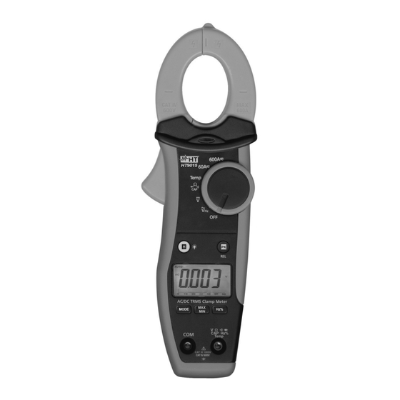
    HT9014 - HT9015 4. BEDIENUNGSANLEITUNG 4.1. GERÄTEBESCHREIBUNG 4.1.1. Funktionsbeschreibung LEGENDE: 1. Zangenbacken 2. Rote LED für berührungs- lose AC Spannungserkennung 3. Zangenöffner 4. Funktionswahlschalter 5. HOLD / Taste 6. PK/REL Taste 7. LCD Anzeige 8. MODE Taste 9. Hz% Taste 10.
  • Seite 76: Beschreibung Der Funktionstasten

    Funktionen: Ω die ausgewählt werden können, in der Temp Position kann zwischen °C und °F Temperatureinheit gewählt werden und in der 60A , Position (nur HT9015) zwischen AC oder DC Strommessung. 600A 4.2.4. MAX/MIN Taste Drücken Sie auf die MAX/MIN Taste, so wird die MAX / MIN Funktion aktiviert.
  • Seite 77: Funktionen Des Drehwahlschalters

    HT9014 - HT9015 4.3. FUNKTIONEN DES DREHWAHLSCHALTERS 4.3.1. AC Spannungsmessung WARNUNG Die max. Eingangsspannung ist DC 1000V bzw. 1000V AC RMS. Versuchen Sie keine Spannung zu messen, die höher ist. Es besteht die Gefahr eines Stromschlages und das Instrument könnte zerstört werden Abb.
  • Seite 78: Dc Spannungsmessung

    HT9014 - HT9015 4.3.2. DC Spannungsmessung WARNUNG Die max. Eingangsspannung ist DC 1000V bzw. 1000V AC RMS. Versuchen Sie keine Spannung zu messen, die höher ist. Es besteht die Gefahr eines Stromschlages und das Instrument könnte zerstört werden Abb. 4 DC Spannungsmessung 1.
  • Seite 79: Widerstandsmessung

    HT9014 - HT9015 4.3.3. Widerstandsmessung WARNUNG Vor jeder Widerstandsmessung in einem Schaltkreis schalten Sie die Versorgungsspannung vom Prüfschaltkreis ab und entladen Sie alle Kondensatoren Abb. 5: Messung von Widerständen 1. Drehen Sie den Schalter in die on Ω CAP Position. Das “Ω” Symbol wird angezeigt.
  • Seite 80: Durchgangsprüfung Und Diodentest

    HT9014 - HT9015 4.3.4. Durchgangsprüfung und Diodentest WARNUNG Vor jeder Widerstandsmessung in einem Schaltkreis schalten Sie die Versorgungsspannung vom Prüfschaltkreis ab und entladen Sie alle Kondensatoren Abb. 6: Durchgangsprüfung und Diodentest 1. Wählen Sie die Ω CAP Position 2. Drücken Sie die MODE Taste und wählen die Durchgangsprüfung. Das Symbol wird im Display angezeigt.
  • Seite 81: Kapazitätsmessung

    HT9014 - HT9015 4.3.5. Kapazitätsmessung WARNUNG Entfernen Sie vor der Messung alle Spannungen vom Messobjekt und entladen Sie alle Kondensatoren, falls vorhanden. Abb. 7: Messung der Kapazität 1. Wählen Sie die Ω CAP Position 2. Drücken Sie die “MODE“ Taste bis das Symbol “nF“ im Display erscheint.
  • Seite 82: Temperaturmessung

    HT9014 - HT9015 4.3.6. Temperaturmessung WARNUNG Vermeiden Sie einen direkten Kontakt des Temperaturfühlers mit Oberflächen die eine Spannung von mehr als 30 VAC oder 60 VDC führen. Abb. 8 Temperaturmessung 1. Wählen Sie die Temp Position 2. Drücken Sie die “MODE“ Taste und wählen Sie die Messeinheit „°C” oder “°K” aus.
  • Seite 83: Dc Strommessung (Nur Ht9015)

    HT9014 - HT9015 4.3.7. DC Strommessung (nur HT9015) WARNUNG Entfernen Sie vor der Messung alle Messleitungen vom Messobjekt und vom Messgerät. Abb. 9 DC Strommessung 1. Drehen Sie den Funktionswahlschalter in eine Position zwischen 60A oder 600A . Sollte der zu erwartende Stromwert unbekannt sein, wählen Sie den höchsten Messbereich.
  • Seite 84: Ac Strommessung

    (nur HT9015). Sollte der zu erwartende Stromwert unbekannt sein, wählen Sie den höchsten Messbereich 3. Drücken Sie die MODE Taste und wählen Sie die “AC” Funktion (nur HT9015) 4. Legen Sie die Leiter nach innen zur Mitte der Klemmbacke getestet werden, um Messungen durchzuführen accurated.
  • Seite 85: Frequenz Und Tastverhältnis

    1. Drehen Sie den Funktionswahlschalter in die Position für Frequenzmessung über die Messleitungen oder in die Position 60A , 600A (nur HT9015) oder 60A∼ or 600A∼ Position (nur HT9014) für Frequenzmessung über die Zangenbacken 2. Durch Drücken auf die Hz% Taste erscheint “Hz”...
  • Seite 86: Wartung Und Pflege

    HT9014 - HT9015 5. WARTUNG UND PFLEGE 5.1. ALLGEMEINE INFORMATIONEN 1. Diese Stromzange ist ein Präzisionsmessgerät. Überschreiten Sie niemals die technischen Grenzwerte bei der Messung oder bei der Lagerung um mögliche Beschädigungen oder Gefahren zu vermeiden. 2. Setzen Sie das Messgerät nicht Umgebungen mit hoher Temperatur, hoher Luftfeuchtigkeit oder direkter Sonneneinstrahlung aus.
  • Seite 87: Technische Daten

    (61 ÷ 400Hz) 1000V Integrierter Sensor für berührungslose AC Spannungsermittlung: LED aktiv bei Phase-Erde Spannung > 100V, 50/60Hz Das Messgerät erzeugt ein akustisches Signal im 1000V Bereich bei VAC>750V AC TRMS Spannung (Autorange) – (HT9015 Modell) Eingangswi Frequenz Messbereich Auflösung Genauigkeit Überlastschutz...
  • Seite 88 0.01A 61 ÷ 400Hz ±(5.0%anz+10dgt) 600.0A 0.1A PEAK Funktion: Ansprechzeit: <10ms ; (*) Bezogen auf Kabel innerhalb des Stadtzentrums von Spannbacken Einfluss der Positionierung des Kabels: ±2.0%anz AC TRMS Strom (HT9015 Modell) Frequenz Messbereich Auflösung Genauigkeit (*) Überlastschutz Messbereich ±(2.2%anz+12dgt) 60.00A...
  • Seite 89: Sicherheit

    HT9014 - HT9015 6.1.1. Sicherheit Sicherheitsstandard: IEC/EN61010-1 Isolation: doppelte, verstärkte Isolation Verschmutzungsgrad: Maximale Höhe: 2000m (6562 ft) Überspannungskategorie: CAT IV 600V, CAT III 1000V gegen Erde 6.1.2. Allgemeine Daten Mechanische Eigenschaften Abmessungen BxHxT: 74 x 215 x 43mm Gewicht (inklusive Batterie):...
  • Seite 90: Garantie

    HT9014 - HT9015 7. GARANTIE 7.1. GARANTIEBESTIMMUNGEN Für dieses Gerät gewähren wir Garantie auf Material- oder Produktionsfehler, entsprechend unseren allgemeinen Geschäftsbedingungen. Während der Garantiefrist behält sich der Hersteller das Recht vor, das Produkt wahlweise zu reparieren oder zu ersetzen. Falls Sie das Gerät aus irgendeinem Grund für Reparatur oder Austausch einschicken müssen, setzen Sie sich bitte zuerst mit dem lokalen Händler in Verbindung, bei dem Sie...
  • Seite 92 Via della Boaria, 40 48018 – Faenza (RA)- Italy Tel: +39-0546-621002 (4 linee r.a.) Fax: +39-0546-621144 Email: ht@htitalia.it http://www.ht-instruments.com...

Diese Anleitung auch für:

Ht9014

Inhaltsverzeichnis