
Verwandte Anleitungen für Danfoss TripleLynx 8 kW

Inhaltszusammenfassung für Danfoss TripleLynx 8 kW
- Seite 1 MAKING MODERN LIVING POSSIBLE TripleLynx User Manual Benutzerhandbuch Manuel d’Utilisateur Manual del Usario Manuale dell’Utente Three-phase – 8, 10, 12.5 and 15 kW SOLAR INVERTERS...
- Seite 2 Choice of Language - Sprachauswahl - Choix de la langue - Selección de idioma - Scelta della lingua Page English UK Seite Deutsch Page Français Página Español Pagina Italiano L00410310-07_2q...
-
Seite 3: Inhaltsverzeichnis
Contents Contents 1. Introduction Introduction Operation Mode Definition 2. Display Display View View 2 Status Production Log Setup 3. Web Server Quick Guide Introduction Supported Characters Access and Initial Setup Setup Wizard Operation Web Server Structure Plant, Group and Inverter Views Additional Information 4. -
Seite 4: Introduction
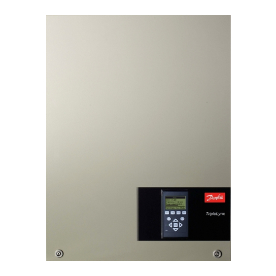
This manual provides information on functionality and maintenance of the TripleLynx solar in- verter. Illustration 1.1: TripleLynx 8 kW, 10 kW, 12.5 kW, 15 kW CE marking - This certifies the conformity of the equipment with the regula- tions which apply in accordance with the directives 2004/108/EC and 2006/95/EC. - Seite 5 1. Introduction Fail Safe (Red LED flashing) If the inverter detects an error in its circuits during the self-test (in connecting mode) or during operation, the inverter goes into fail safe mode. The inverter will remain in fail safe mode until PV power has been absent for a minimum of 10 minutes, or the inverter has been shut down completely (AC + PV).
-
Seite 6: Display
2. Display 2. Display 2.1. Display Note: The display activates up to 10 seconds after power up. The integrated display on the inverter front gives the user access to information about the PV system and the inverter. The display has two modes: Normal The display is in use Power saving... -
Seite 7: View
2. Display 2.1.1. View Menu Structure - View Parameter Description Mode: On grid Displays present inverter mode. See operation mode definitions Prod. today: 12345 kWh Energy production today in kWh. Value from inverter or S0 energy-meter Output Power: 12345 W Current output power in Watt [ --- utilization bar --- ] Shows level of inverter utilisation as % of max. -
Seite 8: Status
2. Display 2.1.3. Status Menu Structure - Status Display Functions Description [-] Ambient Conditions Only applicable if sensors are connected Irradiance. “NC” if not connected Irradiance: 1400W/m PV module temp: 100 PV module temperature. “NC” if not connected Ambient temperature. “NC” if not connected Ambient temp: 20 Irradiation sensor temperature. - Seite 9 2. Display Menu Structure - Status - Continued Display Functions Description [-] Inverter [-] Country: Germany Country setting [-] Internal Conditions Temperature detected at the power module Power module 1: 100 PCB1 (AUX): 100 Temperature detected internally [-] Serial no. and SW ver. [-] Inverter Prod- and serial number: A0010000201...
-
Seite 10: Production Log
2. Display 2.1.4. Production Log Menu Structure - Production Log Display Functions Description Total production: Total production since installation of inverter 123456 kWh Total operating time: Total operating time since installation of inverter 20 hours [-] Production log [-] This week Production from this week Monday: 37 kWh Production from one day shown in KWh... - Seite 11 2. Display Menu Structure - Production Log - Continued Display Functions Description [-] Time stamps Installed: 31-12-07 Date of first grid connection Power down: 21:00:00 When the inverter was last connected to grid Prod. initiated: 06:00:00 When the inverter first connected to grid today [-] De-rating Period of time the inverter has limited power production in total, shown in Total de-rate: 0 h...
-
Seite 12: Setup
The language in the display; changing the display language does Language: English not affect country setting [-] Inverter details Inverter name: Danfoss The inverter's name. Max. 15 characters and not only numbers. The name of the group the inverter is part of Group name: Group name Max. - Seite 13 2. Display *) For TLX Pro only. Menu Structure - Setup - Continued Display Functions Description GPRS connection setup SIM PIN code: 0000 4-8 characters Access point name: name Max. 24 characters User name: user Max. 24 characters Password: password Max.
- Seite 14 2. Display Note: When a value is set in the S0 energy meter calibration menu the inverter disables its own energy counter in order to show the value from the S0 meter. Therefore the energy count will not be shown if a value is set, even though no S0 meter is connected. L00410310-07_2q...
-
Seite 15: Web Server Quick Guide
The Web Server is available in TLX Pro and TLX Pro+ inverters only. Refer to the download area at www.danfoss.com/solar for the newest instructions. 3.2. Supported Characters For all language versions, the Web Server software supports characters compatible with Uni- code. -
Seite 16: Setup Wizard
3. Web Server Quick Guide Illustration 3.1: Product Label The Web Server logon dialog opens. Type 'admin' in the user and password fields, and click [Log in]. At initial logon the inverter runs a setup wizard. 3.3.2. Setup Wizard Step 1 of 7: Master setting To set up a master inverter, click on [Set this inverter as master]. - Seite 17 3. Web Server Quick Guide Illustration 3.3: Step 2 of 7: Display Language Setup, Setup Details . To change the language setting later, refer to Step 3 of 7: Time and date Enter • time in 24-hour format • date •...
- Seite 18 3. Web Server Quick Guide Incorrect setting can have serious consequences for production efficiency. Illustration 3.5: Step 4 of 7: Installed Power Setup, Calibration, PV Array . To change the installed power, refer to Step 5 of 7: Grid code Select the grid code to match the location of the installation.
- Seite 19 3. Web Server Quick Guide Illustration 3.6: Step 5 of 7: Grid Code Note: If the initial and confirmation settings are different, • grid code selection is cancelled • the wizard recommences step 5 If initial and confirmation settings match, but are incorrect, contact service. Step 6 of 7: Replication To replicate the settings from steps 1 to 6 to other inverters in the same network •...
-
Seite 20: Operation
3. Web Server Quick Guide Step 7 of 7: Inverter startup The inverter will start automatically when the installation sequence is complete (see the TripleLynx Installation Manual), and solar radiation is sufficient. The startup sequence, including self-test, takes a few minutes. Illustration 3.8: Step 7 of 7: Inverter startup To change the setup later, access the inverter via the integrated web interface or the display, at inverter level. - Seite 21 3. Web Server Quick Guide Illustration 3.9: Overview Plant name: Displays the current plant name: • Click on the plant name to display the plant view. Change the plant name at [Setup → Plant details]. • Group menu: Displays groups of inverters: •...
-
Seite 22: Plant, Group And Inverter Views
3. Web Server Quick Guide • Contact: Opens a pop-up window which displays Danfoss contact informa- tion. • Logout: Opens the log in / log out dialog box. • Security level: Displays the current security level as explained in the section Security Levels . -
Seite 23: Unit View
3. Web Server Quick Guide Item Unit View Description Plant Inverter Group Overall plant sta- Red: Plant PR < 50 %, or: Any inverter in the network fail safe mode, or - in - missing from the scan list, no contact with the master Yellow: Any inverter in the network - with PR <... -
Seite 24: Troubleshooting
AC and DC (PV) power. If the inverter re- sumes fail safe operation, action must be taken. Service inverter. Table 4.1: Events Note: For more event descriptions, refer to the TripleLynx Reference Manual in the download area at: www.danfoss.com/solar L00410310-07_2q... -
Seite 25: Maintenance
5. Maintenance 5. Maintenance 5.1. Maintenance Normally, the inverter needs no maintenance or calibration. Ensure the heatsink at the rear of the inverter is not covered. Clean the contacts of the PV load switch once per year. Perform cleaning by cycling the switch to on and off positions ten times.The PV load switch is located at the base of the inverter. - Seite 26 Inhaltsverzeichnis Inhaltsverzeichnis 1. Einführung Einführung Definition der Betriebsarten 2. Display Display Ansicht Ansicht 2 Status Energielog Setup 3. Web Server-Kurzanleitung Einführung Unterstützte Zeichen Zugang und Ersteinrichtung Setup-Assistent Betrieb Web Server-Struktur Ansichten „Anlage“, „Gruppe“ und „Wechselrichter“ Zusätzliche Informationen 4. Fehlerbehebung Fehlerbehebung 5.
-
Seite 27: Einführung
Dieses Handbuch enthält Informationen zu Funktionen und zur Wartung des TripleLynx Solar- Wechselrichters. Abbildung 1.1: TripleLynx 8 kW, 10 kW, 12.5 kW, 15 kW CE-Kennzeichnung: Diese Kennzeichnung gibt an, dass die Geräte den gel- tenden Vorschriften der Richtlinien 2004/108/EG und 2006/95/EG entspre- chen. - Seite 28 1. Einführung tung verfügbar ist (wenn das Netz 10 Minuten lang nicht mit Strom versorgt wird). Er geht dann in die Betriebsart „Anschluss erfolgt“ oder „Vom Netz“. Ausfallsicher (Rote LED blinkt) Stellt der Wechselrichter beim Selbsttest (in der Betriebsart „Anschluss erfolgt“) oder während des Betriebs einen Schaltkreisfehler fest, schaltet er in die Betriebsart „Ausfallsicher“.
-
Seite 29: Display
2. Display 2. Display 2.1. Display Anmerkung: Das Display wird maximal 10 Sekunden nach dem Einschalten aktiviert. Der Benutzer hat über das integrierte Display auf der Vorderseite des Wechselrichters Zugang zu allen Informationen über das PV-System und den Wechselrichter. Das Display hat zwei Betriebsarten: Normal Das Display ist in Gebrauch. -
Seite 30: Ansicht
2. Display 2.1.1. Ansicht Menüstruktur – Ansicht Parameter Beschreibung Modus: Am Netz Zeigt die aktuelle Betriebsart des Wechselrichters an. Siehe Definitionen der Betriebsarten Prod. Heute: 12345 kWh Energieerzeugung von heute in kWh. Wert vom Wechselrichter oder S0-Energiemesser. Ausgangsleistung: 12345 W Aktuelle Ausgangsleistung in Watt. -
Seite 31: Status
2. Display 2.1.3. Status Menüstruktur – Status Displayfunktionen Beschreibung [-] Umgebungsbedingungen Nur anwendbar, wenn Sensoren angeschlossen sind Abstrahlung. „NC“, wenn nicht angeschlossen Einstrahlung: 1400 W/m PV-Modultemp.: 100 °C PV-Modultemperatur. „NC“, wenn nicht angeschlossen Umgebungstemp.: 20 °C Umgebungstemperatur. „NC“, wenn nicht angeschlossen Temp. - Seite 32 2. Display Menüstruktur – Status – Fortsetzung Displayfunktionen Beschreibung [-] Wechselrichter [-] Land: Deutschland Ländereinstellung [-] Interne Bedingungen Leistungsmodul 1: 100 °C Am Leistungsmodul erfasste Temperatur PCB1 (AUX): 100 °C Intern erfasste Temperatur [-] Seriennr. und SW-Ver. [-] Wechselrichter Prod.- und Seriennummer: A0010000201 Produktnummer des Wechselrichters 011900H2304...
-
Seite 33: Energielog
2. Display 2.1.4. Energielog Menüstruktur – Energielog Displayfunktionen Beschreibung Energie gesamt: Gesamte Energieerzeugung seit Installation des Wechselrichters. 123.456 kWh Gesamtbetriebsdauer: Gesamtbetriebsdauer seit Installation des Wechselrichters 20 Stunden [-] Energielog [-] Diese Woche Energieerzeugung dieser Woche Montag: 37 kWh Energieerzeugung eines bestimmten Tages in kWh. Dienstag: 67 kWh Mittwoch: 47 kWh Donnerstag: 21 kWh... - Seite 34 2. Display Menüstruktur – Energielog – Fortsetzung Displayfunktionen Beschreibung [-] Zeitstempel Installiert: 31-12-07 Datum des ersten Netzanschlusses Abschaltung: 21:00:00 Letzter Anschluss des Wechselrichters an das Netz Prod. gestartet: 06:00:00 Erster Anschluss des Wechselrichters an das Netz heute. [-] Reduzierung Dauer, während der der Wechselrichter begrenzt Energie erzeugt, angezeigt als Ge- Gesamt-Reduzierung: 0 h samtzeit in Stunden.
-
Seite 35: Setup
Sprache des Displays; Änderungen der Displaysprache ha- Sprache: Deutsch ben keine Auswirkung auf die Ländereinstellung [-] Wechselrichterdetails Wechselrichtername: Der Name des Wechselrichters. Max. 15 Zeichen (nicht aus- Danfoss schließlich Zahlen). Gruppenname: Name der Wechselrichter-Gruppe Gruppenname Max. 15 Zeichen [-] Master-Modus Master-Mod.: Aktiviert... - Seite 36 2. Display *) Nur für TLX Pro. Menüstruktur – Setup – Fortsetzung Displayfunktionen Beschreibung GPRS-Verbindungseinr. SIM PIN-Code: 0000 4 - 8 Zeichen Zugangspunktname: Name Max. 24 Zeichen Benutzername: Benutzer Max. 24 Zeichen Kennwort: Kennwort Max. 24 Zeichen Roaming: Deaktiviert [-] Data-Warehouse-Service Upl.-Kan.: LAN Uploadzeit (h:m): 14:55 Erfordert Energieerzeugungsdaten über einen Zeitraum von mindes-...
- Seite 37 2. Display Anmerkung: Wenn ein Wert im Kalibriermenü für den S0-Energiemesser eingestellt ist, deaktiviert der Wechselrichter seinen eigenen Energiezähler, um den Wert vom S0-Messer zu zeigen. Daher wird die Energiezählung nicht gezeigt, wenn ein Wert eingestellt ist, auch wenn kein S0-Mes- ser angeschlossen ist.
-
Seite 38: Web Server-Kurzanleitung
In diesen Anweisungen wird der TLX Pro Web Server erläutert, der den Remote-Zugriff auf den Wechselrichter erleichtert. Der Web Server ist ausschließlich in TLX Pro- und TLX Pro+-Wechselrichtern integriert. Aktuelle Anweisungen finden Sie im Download-Bereich unter www.danfoss.com/solar. 3.2. Unterstützte Zeichen Die Web Server-Software unterstützt für alle Sprachversionen mit Unicode kompatible Zeichen. -
Seite 39: Setup-Assistent
3. Web Server-Kurzanleitung Abbildung 3.1: Produktschild Das Web Server-Anmeldedialogfeld wird geöffnet. Geben Sie in die Felder für Benutzer und Passwort „admin“ ein und klicken Sie auf [An- melden]. Beim ersten Anmelden wird ein Setup-Assistent gestartet. 3.3.2. Setup-Assistent Schritt 1 von 7: Master-Einstellung Klicken Sie auf [Diesen Wechselrichter als Master einstellen], um einen Master-Wechselrichter einzurichten. - Seite 40 3. Web Server-Kurzanleitung Abbildung 3.3: Schritt 2 von 7: Display-Sprache Setup, Setup-De- Informationen zum späteren Ändern der Spracheinstellung finden Sie unter tails . Schritt 3 von 7: Uhrzeit und Datum Geben Sie Folgendes ein: • Uhrzeit im 24-Stunden-Format • Datum •...
- Seite 41 3. Web Server-Kurzanleitung Falsche Einstellungen können schwerwiegende Folgen für die Produktionseffizienz haben. Abbildung 3.5: Schritt 4 von 7: Anschlussleistung Setup, Kalibrierung, PV-Anla- Informationen zum Ändern der Anschlussleistung finden Sie unter ge . Schritt 5 von 7: Netzcode Wählen Sie den Netzcode gemäß des Installationsorts aus. Wählen Sie zur Erfüllung der Mittels- pannungsnetzanforderungen einen Netzcode mit der Endung MV aus.
- Seite 42 3. Web Server-Kurzanleitung Abbildung 3.6: Schritt 5 von 7: Netzcode Anmerkung: Wenn die ersten Einstellungen nicht mit den bestätigten Einstellungen übereinstimmen, • wird die Netzcodeauswahl abgebrochen. • Der Assistent kehrt zu Schritt 5 zurück. Wenn die ersten Einstellungen und die bestätigten Einstellungen übereinstimmen, aber in- korrekt sind, wenden Sie sich an den Service.
-
Seite 43: Betrieb
3. Web Server-Kurzanleitung Abbildung 3.7: Schritt 6 von 7: Replikation Schritt 7 von 7: Starten des Wechselrichters Der Wechselrichter startet automatisch, wenn die Installationsfolge abgeschlossen ist (siehe TripleLynx-Installationsanleitung) und die Sonneneinstrahlung nicht ausreichend ist. Der Startvorgang einschließlich Selbsttest dauert einige Minuten. Abbildung 3.8: Schritt 7 von 7: Starten des Wechselrichters Um den Setup später zu ändern, greifen Sie über die integrierte Webschnittstelle oder das Dis- play auf den Wechselrichter auf Wechselrichterebene zu. - Seite 44 3. Web Server-Kurzanleitung Abbildung 3.9: Übersicht Anlagenname: Zeigt den aktuellen Namen der Anlage an: • Klicken Sie auf den Anlagennamen, um die Anlagenansicht anzuzeigen. Ändern Sie den Anlagennamen unter [Setup → Anlagendetails]. • Gruppenmenü: Zeigt die Gruppen der Wechselrichter: • Standardmäßig werden die Wechselrichter der Gruppe 1 zugeordnet.
-
Seite 45: Ansichten „Anlage", „Gruppe" Und „Wechselrichter
Sprache: Öffnet ein Pop-up-Fenster. Klicken Sie auf eine Flagge, um die Sprache von Web Server auf die gewünschte Sprache für die aktuelle Sitzung einzustellen. • Kontakt: Öffnet ein Pop-up-Fenster mit den Danfoss-Kontaktdaten. • Abmeldung: Öffnet das Dialogfeld für die Anmeldung bzw. Abmeldung. •... -
Seite 46: Beschreibung
3. Web Server-Kurzanleitung Element Ein- Ansicht Beschreibung heit Anlage Wech- selrich- Gruppe Gesamtanlagen- Rot: Nutzungsgrad der Anlage < 50 % oder: status Ein beliebiger Wechselrichter im Netzwerk Sicherheitsprüfungs-M odus oder – im – fehlt auf der Prüfliste, keine Verbindung mit dem Mas- Gelb: Ein beliebiger Wechselrichter im Netzwerk –... -
Seite 47: Fehlerbehebung
4. Fehlerbehebung 4. Fehlerbehebung 4.1. Fehlerbehebung Beachten Sie, dass alle Arbeiten an Wechselrichtern und elektrischen Installatio- nen nur von geschultem und autorisiertem, mit elektrischen Anlagen und Sicher- heitsfragen vertrautem Personal vorgenommen werden dürfen. Falls der Wechselrichter nicht die erwartete Energie liefert, arbeiten Sie die Checkliste ab, bevor Sie den Service anrufen. - Seite 48 4. Fehlerbehebung Anmerkung: Weitere Ereignisbeschreibungen siehe TripleLynx-Referenzhandbuch Downloadbereich unter www.danfoss.com/solar L00410310-07_2q...
-
Seite 49: Wartung
5. Wartung 5. Wartung 5.1. Wartung Der Wechselrichter erfordert im Normalfall keine Instandhaltung oder Kalibrierung. Stellen Sie sicher, dass der Kühlkörper an der Rückseite des Wechselrichters nicht verdeckt wird. Reinigen Sie die Kontakte des PV-Lastschalters einmal pro Jahr. Führen Sie die Reinigung durch, indem Sie den Schalter zehnmal ein- und ausschalten. - Seite 50 Table des matières Table des matières 1. Introduction Introduction Définition des modes de fonctionnement 2. Écran Écran Vue 2 Etats Journal de production Configuration 3. Guide rapide du Web Server Introduction Caractères pris en charge Accès et configuration initiale Assistant de configuration Fonctionnement Structure du Web Server Vues de l'onduleur, du groupe et de l'installation...
-
Seite 51: Introduction
Ce manuel fournit des informations sur les fonctions et la maintenance de l'onduleur solaire TripleLynx. Illustration 1.1: TripleLynx 8 kW, 10 kW, 12.5 kW, 15 kW Marquage CE - ce marquage certifie la conformité de l'équipement aux rè- glements en vigueur, conformément aux directives 2004/108/CE et 2006/95/CE. - Seite 52 1. Introduction Sécurité intégrée (voyant rouge clignotant) Si l'onduleur détecte une erreur dans ses circuits pendant l'auto-test (en mode Connexion en cours) ou en cours de fonctionnement, il bascule en mode Sécurité intégrée. L'onduleur reste en mode Sécurité intégrée jusqu'à ce que la puissance PV soit absente pendant au moins 10 minutes ou que l'onduleur s'éteigne complètement (CA + PV).
-
Seite 53: Écran
2. Écran 2. Écran 2.1. Écran Remarque: L'écran reste activé pendant 10 secondes maximum après la mise sous tension. L'écran intégré à l'avant de l'onduleur permet à l'utilisateur d'accéder à toutes les informations relatives à l'installation PV et à l'onduleur. L'écran comporte deux modes : Normal L'écran fonctionne. -
Seite 54: Vue
2. Écran 2.1.1. Vue Structure du menu - Vue Paramètre Description Mode : En ligne Affiche le mode activé sur l'onduleur. Voir les définitions des modes de fonctionnement Prod. du jour : 12345 kWh Production d'énergie du jour en kWh. Valeur de l'onduleur ou du compteur d'énergie C0 Puis. -
Seite 55: Etats
2. Écran 2.1.3. Etats Structure du menu - Etats Fonctions d'affichage Description [-] Conditions climatiques S'applique uniquement si des capteurs sont connectés Éclairement énergétique. Non connecté s'affiche en l'absence de Irradiance : 1400 W/m connexion Température du module PV. Non connecté s'affiche en l'absence de T°... - Seite 56 2. Écran Structure du menu - Etats - suite Fonctions d'affichage Description [-] Onduleur [-] Pays : Allemagne Réglage spécifique au pays [-] Conditions internes Module puis. 1 : 100 °C Température détectée au niveau du module de puissance PCB 1 (AUX) : 100 °C Température détectée en interne [-] N°...
-
Seite 57: Journal De Production
2. Écran 2.1.4. Journal de production Structure du menu - Journal de production Fonctions d'affichage Description Production totale : Production totale d'énergie depuis l'installation de l'onduleur 123456 kWh Temps fct total : Temps de fonctionnement total depuis l'installation de l'onduleur 20 heures [-] Journal de production [-] Cette semaine... - Seite 58 2. Écran Structure du menu - Journal de production - suite Fonctions d'affichage Description [-] Horodatage Installé : 31-12-07 Date du premier raccordement au réseau Hors tension : 21:00:00 Dernière connexion de l'onduleur au réseau Prod. lancée : 06:00:00 Première connexion de l'onduleur au réseau aujourd'hui [-] Réduction Durée pendant laquelle l'onduleur a limité...
-
Seite 59: Configuration
Langue : Anglais pas le réglage spécifique au pays. [-] Détails onduleur Nom onduleur : Nom attribué à l'onduleur. 15 caractères max. mélangeant let- Danfoss tres et chiffres. Nom groupe : Nom du groupe auquel appartient l'onduleur Nom groupe 15 caractères max. - Seite 60 2. Écran *) Pour le TLX Pro uniquement. Structure du menu - Configuration - suite Fonctions d'affichage Description Conf. connexion GPRS Code PIN SIM : 0000 4-8 caractères Nom point d'accès : 24 caractères max. Nom d'utilisateur : utilisateur 24 caractères max. Mot de passe : mot de passe 24 caractères max.
- Seite 61 2. Écran Remarque: Lorsqu'une valeur est réglée dans le menu d'étalonnage du compteur d'impulsions kWh S0, l'onduleur désactive son propre compteur d'impulsions kWh afin d'afficher la valeur du comp- teur S0. Le compte d'impulsions kWh ne sera donc pas affiché si une valeur est définie mê- me si aucun compteur S0 n'est connecté.
-
Seite 62: Guide Rapide Du Web Server
Ces instructions décrivent le Web Server du TLX Pro, qui facilite l'accès à distance à l'onduleur. Le Web Server est disponible sur les onduleurs TLX Pro et TLX Pro+ uniquement. Se reporter à la rubrique de téléchargement sur www.danfoss.com/solar pour consulter les ins- tructions les plus récentes. -
Seite 63: Assistant De Configuration
3. Guide rapide du Web Server Illustration 3.1: Étiquette du produit La boîte de dialogue d'ouverture de session du Web Server s'ouvre. Saisir « admin » dans les champs d'utilisateur et de mot de passe et cliquer sur [Se connecter]. Lors de la première ouverture de session, l'onduleur lance un assistant de configura- tion. - Seite 64 3. Guide rapide du Web Server Illustration 3.3: Étape 2 sur 7 : langue d'affichage Configuration, Détails de configuration . Pour modifier la langue ultérieurement, voir Étape 3 sur 7 : heure et date Saisir • l'heure au format 24 heures, •...
- Seite 65 3. Guide rapide du Web Server Un réglage incorrect peut avoir de lourdes conséquences sur le rendement de la production. Illustration 3.5: Étape 4 sur 7 : puissance installée Configuration, Étalonnage, Panneau PV . Pour modifier la puissance installée, se reporter à Étape 5 sur 7 : code réseau Sélectionner le code réseau qui correspond à...
- Seite 66 3. Guide rapide du Web Server Illustration 3.6: Étape 5 sur 7 : code réseau Remarque: Si le réglage initial et le réglage de confirmation diffèrent, • la sélection du code réseau est annulée, et • l'assistant revient au début de l'étape 5. Si le réglage initial et le réglage de confirmation correspondent, mais sont incorrects, contac- ter le service d'assistance.
-
Seite 67: Fonctionnement
3. Guide rapide du Web Server Illustration 3.7: Étape 6 sur 7 : réplication Étape 7 sur 7 : démarrage des onduleurs L'onduleur démarre automatiquement lorsque la séquence d'installation est achevée (voir le manuel d'installation du TripleLynx) et lorsque le rayonnement solaire est suffisant. La séquence de démarrage, auto-test compris, prend quelques minutes. - Seite 68 3. Guide rapide du Web Server Illustration 3.9: Présentation Nom de l'installation : affiche le nom actuel de l'installation : • Cliquer sur le nom de l'installation pour afficher la vue de l'installation. Modifier le nom de l'installation dans [Configuration → Détails de l'installa- •...
-
Seite 69: Vues De L'onduleur, Du Groupe Et De L'installation
Web Server selon les besoins de la session active. • Contact : ouvre une fenêtre contextuelle qui affiche les informations de con- tact de Danfoss. • Déconnexion : ouvre la boîte de dialogue d'ouverture/de fermeture de ses- sion. -
Seite 70: Informations Supplémentaires
3. Guide rapide du Web Server Élément Unité Affichage Description Installa- Ondu- tion et leur groupe État global de Rouge : RP de l'installation < 50 % ou : l'installation un onduleur du réseau Sécurité intégrée ou - est en mode - est absent de la liste d'analyse, aucun contact avec le maître. -
Seite 71: Dépannage
4. Dépannage 4. Dépannage 4.1. Dépannage Seul du personnel formé, autorisé et expérimenté en matière de systèmes électri- ques et de sécurité est habilité à intervenir sur des onduleurs et des installations électriques. Si l'onduleur ne fournit pas autant d'énergie que prévu, repasser la liste de vérification avant de contacter la maintenance. - Seite 72 4. Dépannage Remarque: Pour plus de descriptions d'événement, se référer au Manuel de référence TripleLynx dispo- nible dans la rubrique de téléchargement du site : www.danfoss.com/solar L00410310-07_2q...
-
Seite 73: Maintenance
5. Maintenance 5. Maintenance 5.1. Maintenance Normalement, l'onduleur ne nécessite ni maintenance, ni étalonnage. S'assurer que le dissipateur de chaleur à l'arrière de l'onduleur n'est pas couvert. Nettoyer les contacts de l'interrupteur PV une fois par an. Effectuer le nettoyage en mettant sous tension, puis hors tension l'interrupteur PV dix fois de suite. - Seite 74 Índice Índice 1. Introducción Introducción Definición del modo de funcionamiento 2. Pantalla Pantalla Visualización Visualización 2 Estado Registro de producción Configuración 3. Guía rápida de Web Server Introducción Caracteres admitidos Acceso y configuración inicial Asistente de configuración Funcionamiento Estructura del Web Server Vistas de planta, grupo e inversor Información adicional 4.
-
Seite 75: Introducción
Este manual proporciona información sobre las funciones y mantenimiento del inversor solar TripleLynx. Ilustración 1.1: TripleLynx 8 kW, 10 kW, 12.5 kW, 15 kW Marcado CE: certifica la conformidad del equipo con la normativa aplicable según lo establecido en las directivas 2004/108/CE y 2006/95/CE. - Seite 76 1. Introducción A prueba de fallos (LED rojo parpadeando) Si el inversor detecta un error en sus circuitos durante la autoprueba (en modo «Conectando») o durante el funcionamiento, el inversor pasará al modo «A prueba de fallos» El inversor per- manecerá...
-
Seite 77: Pantalla
2. Pantalla 2. Pantalla 2.1. Pantalla Nota: La pantalla tarda como máximo 10 segundos en activarse tras el arranque. La pantalla integrada en la parte frontal del inversor proporciona al usuario acceso a la informa- ción del sistema FV y del inversor. La pantalla tiene dos modos: Normal La pantalla está... -
Seite 78: Visualización
2. Pantalla 2.1.1. Visualización Estructura del menú: visualización Parámetro Descripción Modo: conectado a la red Muestra el modo actual del inversor. Consulte las definiciones de los modos de funciona- miento. Produc. de hoy: 12 345 kWh Producción de energía de hoy en kWh. Valor del inversor o contador de energía S0 Potencia de salida: 12 345 W Potencia de salida actual en vatios [ --- barra de uso --- ] Muestra el nivel de uso del inversor en % de uso máximo. -
Seite 79: Estado
2. Pantalla 2.1.3. Estado Estructura del menú: estado Funciones de la pantalla Descripción [-] Condiciones ambientales Solo aplicable si los sensores están conectados. Irradiancia. «NC» si no está conectado. Irradiancia: 1400 W/m Temp. módulo FV: 100 °C Temperatura del módulo FV. «NC» si no está conectado. Temp. - Seite 80 2. Pantalla Estructura del menú: estado (continuación) Funciones de la pantalla Descripción [-] Inversor [-] País: Alemania Ajuste de red [-] Condiciones internas Módulo de potencia 1: 100 °C Temperatura detectada en el módulo de potencia PCB1 (AUX): 100 °C Temperatura detectada internamente [-] N.º...
-
Seite 81: Registro De Producción
2. Pantalla 2.1.4. Registro de producción Estructura del menú: registro de producción Funciones de la pantalla Descripción Producción total: Producción total desde la instalación del inversor 123 456 kWh Tiempo de funcionamiento total: Tiempo de funcionamiento total desde la instalación del inversor 20 horas [-] Registro de producción [-] Esta semana... - Seite 82 2. Pantalla Estructura del menú: registro de producción (continuación) Funciones de la pantalla Descripción [-] Marcas de hora Instaladas: 31-12-07 Fecha de la primera conexión de red Bajada de potencia: 21:00:00 Última conexión del inversor a la red Prod. iniciada a las: 06:00:00 Primera conexión del inversor a la red hoy [-] Reducción Periodo en el que el inversor tiene una producción de potencia total limita-...
-
Seite 83: Configuración
[-] Detalles del inversor Nombre del inversor: Nombre del inversor. Máximo de 15 caracteres y Danfoss no solo números. Nombre del grupo al que pertenece el inversor. Nombre del grupo: Nombre del grupo Máximo de 15 caracteres... - Seite 84 2. Pantalla *) Solo para TLX Pro. L00410310-07_2q...
- Seite 85 2. Pantalla Estructura del menú: configuración (continuación) Funciones de la pantalla Descripción Ajuste de conexión GPRS Código PIN SIM: 0000 4-8 caracteres Nombre de punto de acceso: nombre Máximo de 24 caracteres Nombre de usuario: usuario Máximo de 24 caracteres Contraseña: contraseña Máximo de 24 caracteres...
- Seite 86 2. Pantalla *) Solo para TLX Pro . Nota: Cuando se configura un valor en el menú de calibración del contador de energía S0, el inver- sor deshabilita su propio contador de energía para mostrar el valor del contador S0. Por lo tanto, el recuento de energía no se mostrará...
-
Seite 87: Guía Rápida De Web Server
Estas instrucciones describen el TLX Pro Web Server, que facilita acceso remoto al inversor. Web Server está disponible únicamente en inversores TLX Pro y TLX Pro+. Consulte el área de descarga en www.danfoss.com/solar para obtener las instrucciones mas re- cientes. -
Seite 88: Asistente De Configuración
3. Guía rápida de Web Server Ilustración 3.1: Etiqueta del producto Se abre el cuadro de diálogo de inicio de sesión de Web Server. Escriba «administrador» en los campos usuario y contraseña y haga clic en [Conectar]. Al iniciar la sesión, el inversor ejecuta un asistente de configuración. 3.3.2. - Seite 89 3. Guía rápida de Web Server Ilustración 3.3: Paso 2 de 7: Idioma de la pantalla Configuración, Detalles de configuración . Para cambiar el ajuste de idioma más tarde, consulte Paso 3 de 7: Fecha y hora Intro • Hora en formato de 24 horas •...
- Seite 90 3. Guía rápida de Web Server Ilustración 3.5: Paso 4 de 7: Potencia instalada Configuración, Calibración, Matriz FV. Para cambiar la potencia instalada, consulte Paso 5 de 7: Ajuste de red Seleccione el ajuste de red para corresponderse con la instalación. Para satisfacer los requisitos de red de tensión media, seleccione un ajuste de red que termine en MV.
- Seite 91 3. Guía rápida de Web Server Nota: Si los ajustes iniciales y de confirmación son distintos, • la selección de ajuste de red se cancela • y el asistente se reanuda en el paso 5. Si los ajustes iniciales y de confirmación coinciden pero no son correctos, póngase en con- tacto con la asistencia técnica.
-
Seite 92: Funcionamiento
3. Guía rápida de Web Server Ilustración 3.8: Paso 7 de 7: Puesta en marcha del inversor Para cambiar la configuración más tarde, acceda al inversor a través de la interfaz web integra- da o la pantalla, en el nivel de inversor. •... -
Seite 93: Vistas De Planta, Grupo E Inversor
Web Server al idioma deseado para esta sesión. • Contacto: abre una ventana emergente que muestra la información de con- tacto de Danfoss. • Cierre de sesión: abre el cuadro de diálogo de inicio / cierre de sesión. - Seite 94 3. Guía rápida de Web Server Ilustración 3.10: Visualización de la planta Concepto Uni- Visualización Descripción Planta y Inversor grupo Estado general de Rojo: PR planta <50 %, o: la planta Cualquier inversor en la red - en modo a prueba de fallos, o - no existe en la lista de exploración, sin contacto con el maestro Amarillo: Cualquier inversor en la red...
-
Seite 95: Información Adicional
3. Guía rápida de Web Server Nota: Para calcular la proporción de rendimiento PR se necesita un sensor de irradiación, consulte [Configuración → Calibración]. 3.5. Información adicional Consulte el manual del usuario de Web Server si desea obtener más información sobre: •... -
Seite 96: Resolución De Problemas
4. Resolución de problemas 4. Resolución de problemas 4.1. Resolución de problemas Los inversores y las instalaciones eléctricas solo deben ser manipulados por perso- nal autorizado, debidamente formado y familiarizado con los sistemas eléctricos y las cuestiones de seguridad. Si el inversor no suministra energía como es de esperar, revise el lista de comprobaciones si- guiente antes de llamar al servicio técnico. - Seite 97 4. Resolución de problemas Nota: Puede encontrar más descripciones de incidencias en el Manual de referencia delTripleLynx en la zona de descargas en: www.danfoss.com/solar L00410310-07_2q...
-
Seite 98: Mantenimiento
5. Mantenimiento 5. Mantenimiento 5.1. Mantenimiento Normalmente, el inversor no necesita mantenimiento ni calibración. Asegúrese de que no se cubre el disipador térmico en la parte posterior del inversor. Limpie los contactos del dispositivo FV una vez al año. Lleve a cabo la limpieza encendiendo y apagando el interruptor diez veces. - Seite 99 Sommario Sommario 1. Introduzione Introduzione Definizione dei modi di funzionamento 2. Display Display Vista Vista 2 Stato Reg. produzione Impostazione 3. Web Server Guida rapida Introduzione Caratteri supportati Accesso e setup iniziale Install. guidata Funzionamento Web Server Struttura Viste impianto, gruppo e inverter Informazioni supplementari 4.
-
Seite 100: Introduzione
Questo manuale fornisce informazioni sulla funzionalità e la manutenzione dell'inverter solare TripleLynx. Disegno 1.1: TripleLynx 8 kW, 10 kW, 12.5 kW, 15 kW Marcatura CE – Certifica la conformità dell'attrezzatura ai regolamenti appli- cabili in conformità con le direttive 2004/108/EC e 2006/95/EC 1.2. - Seite 101 1. Introduzione A prova di guasto (LED rosso lampeggiante) Se rileva un errore nei propri circuiti durante il test automatico in modalità di connessione o du- rante il funzionamento l'inverter passa alla modalità a prova di guasto. L'inverter rimarrà in mo- dalità...
-
Seite 102: Display
2. Display 2. Display 2.1. Display Nota: Il display si attiva entro 10 secondi dall'accensione. L'utente ha accesso alle informazioni relative al sistema FV e all'inverter grazie al display inte- grato nella parte anteriore dell'inverter. Il display presenta due modalità: Normale Il display è... -
Seite 103: Vista
2. Display 2.1.1. Vista Struttura dei menu - Vista Parametro Descrizione: Modalità: Connesso alla rete Visualizza l'attuale modalità di funzionamento dell’inverter. Vedere le definizioni dei modi di funzionamento Prod. oggi: 12345 kWh Produzione di energia oggi in kWh. Valore dall'inverter o dal contatore S0 Potenza in uscita: 12345 W Potenza correntemente erogata in Watt [ --- barra d'uso --- ]... -
Seite 104: Stato
2. Display 2.1.3. Stato Struttura dei menu - Stato Funzioni visualizzate Descrizione: [-] Condizioni ambientali Applicabile solo se i sensori sono connessi Irraggiamento. “NC” se non connesso Irraggiamento: 1400W/m Temp. modulo FV: 100 Temperatura del modulo FV. "NC" se non connesso Temperatura ambiente. - Seite 105 2. Display Struttura Menu - Stato - Continua Funzioni visualizzate Descrizione: [-] Inverter [-] Paese: Germania Impostazione paese [-] Condizioni interne Temperatura rilevata sul modulo di potenza Modulo di potenza 1: 100 PCB 1 (AUS): 100 Temperatura interna rilevata [-] N. seriale e vers. SW [-] Inverter Cod.
-
Seite 106: Reg. Produzione
2. Display 2.1.4. Reg. produzione Struttura menu - Reg. produzione Funzioni visualizzate Descrizione: Produzione totale: Produzione totale dall'installazione dell'inverter 123456 kWh Temp. funzione totale: Tempo di funzionamento totale dall'installazione dell'inverter 20 ore [-] Reg. produzione [-] Questa settimana Produzione da questa settimana Lunedì: 37 kWh Produzione di un giorno espressa in kWh Martedì: 67 kWh... - Seite 107 2. Display Struttura Menu - Reg. produzione - Continua Funzioni visualizzate Descrizione: [-] Registr. cronol. Installato: 31-12-07 Data di prima connessione alla rete di distribuzione Spegnimento: 21:00:00 Quando l’inverter è stato connesso alla rete di distribuzione per l'ultima volta Quando l’inverter è stato connesso alla rete di distribuzione per la prima vol- Avvio produz.: 06:00:00 [-] Declassamento Periodo di tempo in cui l'inverter ha una produzione energetica totale limita-...
-
Seite 108: Impostazione
La lingua nel display; la modifica della lingua del display non Lingua: Inglese influisce sull'impostazione del paese [-] Dati inverter Nome inverter: Danfoss Il nome dell'inverter Massimo 15 caratteri e non solo numeri. Nome del gruppo: Il nome del gruppo di cui fa parte l'inverter Nome gruppo Max 15 caratteri [-] Modalità... - Seite 109 2. Display *) Solo per TLX Pro. Struttura menu - Impostazione - segue Funzioni visualizzate Descrizione: Impost. conness. GPRS Codice PIN SIM: 0000 4-8 caratteri Nome punto di accesso: nome Max 24 caratteri Nome utente: utente Max 24 caratteri Password: password Max 24 caratteri Roaming: Disabilitato...
- Seite 110 2. Display Nota: Quando un valore è impostato nel menu di calibrazione del contatore S0 l'inverter disabilita il proprio contatore in modo da poter visualizzare la lettura del contatore S0. Quindi il contato- re non sarà visualizzato se viene impostata una lettura, anche se nessun contatore S0 è con- nesso.
-
Seite 111: Web Server Guida Rapida
Queste istruzioni descrivono il TLX Pro Web Server che facilita l'accesso remoto all'inverter. Il Web Server è disponibile solo negli inverter TLX Pro e TLX Pro+. Fare riferimento all'area di download in www.danfoss.com/solar per le istruzioni più recenti. 3.2. Caratteri supportati Per tutte le versioni di lingua, il software del Web Server supporta i caratteri compatibili con Unicode. -
Seite 112: Install. Guidata
3. Web Server Guida rapida Disegno 3.1: Etichetta del prodotto Si apre la finestra di dialogo Web Server di login. Digitare 'admin' nei campi utente e password e fare clic su [Log in]. Dopo il login iniziale l'inverter esegue un'installazione guidata. 3.3.2. - Seite 113 3. Web Server Guida rapida Disegno 3.3: Passo 2 di 7: lingua di visualizzazione Setup, Per modificare l'impostazione della lingua in un secondo momento, fare riferimento a Dettagli setup . Passo 3 di 7: ora e data Invio • orario nel formato a 24 ore. •...
- Seite 114 3. Web Server Guida rapida Un'impostazione scorretta può avere gravi conseguenze per l'efficienza produttiva. Disegno 3.5: Passo 4 di 7: potenza installata Setup, Calibrazione, Array FV . Per modificare la potenza installata, fare riferimento a Passo 5 di 7: Cod. rete Selezionare il codice di rete che corrisponda al luogo dell'impianto.
- Seite 115 3. Web Server Guida rapida Nota: Se le impostazioni iniziali e di conferma sono diverse, • la selezione del codice di rete viene cancellata • la procedura guidata ricomincia dal passo 5 Se le impostazioni iniziali e di conferma corrispondono, ma sono scorrette, contattare l'assi- stenza.
-
Seite 116: Funzionamento
3. Web Server Guida rapida Disegno 3.8: Passo 7 di 7: avvio dell'inverter Per modificare il setup in un secondo momento, accedere all'inverter tramite l'interfaccia web o il display a livello di inverter. • Per modificare il nome dell'inverter, andare a [Setup → Dettagli inverter] Per abilitare la modalità... -
Seite 117: Viste Impianto, Gruppo E Inverter
Lingua: apre una finestra a comparsa. Fare clic sulla bandiera del paese per cambiare la lingua del Web Server alla lingua desiderata la sessione attiva. • Contatti: apre una finestra a comparsa che visualizza l'informazione di con- tatto di Danfoss. • Logout: apre la casella di dialogo di log-in / log-out. •... - Seite 118 3. Web Server Guida rapida Disegno 3.10: Visualizzazione dell'impianto Elemento Unità Visualizza Descrizione: Impianto Inverter e gruppo Stato impianto ge- Rosso: PR impianto < 50% oppure: nerale Qualsiasi inverter nella rete - in modalità a prova di guasto oppure - mancante dalla lista di scansione, nessun contatto con il master Giallo: Qualsiasi inverter nella rete - con PR <...
-
Seite 119: Informazioni Supplementari
3. Web Server Guida rapida 3.5. Informazioni supplementari Per ulteriori informazioni fare riferimento al manuale dell’utente Web Server per saperne di più • Avviamento dell'inverter e controllo delle impostazioni • Messaggistica • Grafici • Accesso remoto • Caricamento portale Web •... -
Seite 120: Risoluzione Dei Problemi
5 minuti e riapplicare l'alimentazione CA e CC. Se l'inverter ri- prende il funzionamento a prova di guasto, è necessario interveni- re. Occorre intervenire sull'inverter. Tabella 4.1: Eventi Nota: Per maggiori descrizioni di eventi, fare riferimento al Manuale di riferimento TripleLynx nell'a- rea di download in: www.danfoss.com/solar L00410310-07_2q... -
Seite 121: Manutenzione
5. Manutenzione 5. Manutenzione 5.1. Manutenzione Di norma gli inverter non richiedono manutenzione o taratura. Assicurarsi che il dissipatore di calore sul lato posteriore dell'inverter non sia coperto. Pulire i contatti sul sezionatore sotto carico FV una volta all'anno. Effettuare la pulizia commu- tando l'interruttore alle posizioni on e off per dieci volte. - Seite 122 139B0491 Danfoss can accept no responsibility for possible errors in catalogues, brochures and other printed material. Danfoss reserves the right to alter its products without notice. This also applies to products already on order provided that such alterations can be made without subsequential changes being necessary in specifications already agreed.