Carel MasterCella Split Benutzerhandbuch
cod. +050000860 - rel. 1.0 - 22/01/02
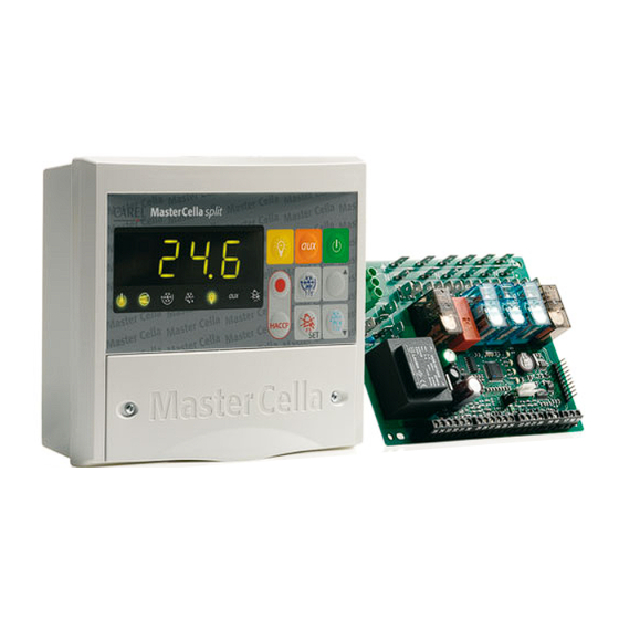
MTSTKIT000 - Kit montaggio a pannello / Panel mounting kit / Kit pour le montage encastré / Kit für Frontmontage / Kit de montaje en panel
Attenzione!
Per il montaggio a pannello seguire
le seguenti istruzioni presenti nel
manuale a pag. 6.
Montaggio a pannello
• Praticare nel pannello un foro di
dimensioni 182x153 mm.
• Svitare le due viti frontali (vedi a, b)
ed estrarre la portina centrale (c).
• Svitare le due viti (d, e) che tengono
unite le parti coperchio inferiore e
frontale del MasterCella Split
e separare le due parti.
• Inserire sul frontale il kit MTSTKIT000
(guarnizione sovrapposta a quella
interna + pannello metallico).
• Praticare nella parte posteriore due
fori (nella parte preforata - f, g).
• Unire la parte posteriore e il frontale,
con il pannello nel mezzo, fissando il
tutto con le due viti (dimensioni
4x20 mm) contenute nel kit.
N.B. È necessario rimuovere i due
denti superiori di fissaggio (h) della
parte frontale prima dell'inserimento a
pannello. Praticare il foro sulla parte
superiore (l) o inferiore (i) del retro per
il passaggio dei cavi. Il passo delle
filettature previste varia da PG9
(diametro 16 mm) a PG21 (diametro 29
mm). È consigliabile usare un trapano
o una fresa per facilitare l'operazione di
foratura. Collegare i fili alla morsettiera.
Quindi avvitare la portina (c).
Warning!
For panel mounting please refer to
the following instructions on page 6
of the manual.
Panel mounting
• Make a hole in the panel with the
following dimensions: 182x153mm.
• Unscrew the two frontal screws (see
a, b) and take out the central door (c).
• Unscrew the two screws (d, e) that
keep connected the lower and frontal
cover of the MasterCella Split and
separate the two parts.
• Insert on the front panel the kit
MTSTKIT000 (gasket on top of the
internal gasket + metal panel).
• Make two holes in the back part
(in the perforated part- f, g).
• Join the back part and the front, with
the panel in between, and fix the whole
with the two screws (dimensions:
4x20mm) that are contained in the kit.
N.B. It is necessary to remove the two
upper fixing teeth (h) of the frontal part
before the panel insertion. Make the
hole in the back upper (l) or lower
part (i) to allow the cable passage.
The pitches of the established threads
ranges from PG9 (diameter: 16mm) to
PG21 (diameter: 29mm). In order to
make easier the drilling operation, the
use of a drill or a cutter is suggested.
Connect the cables to the terminal
block. Then screw the door (c).
GB
Attention!
Pour le montage encastré suivre les
instructions suivantes publiées dans
le manuel à la page 6.
Montage encastré
• Faire une découpe de 182x153 mm.
• Dévisser les deux vis frontales (a, b)
et ôter le couvercle central (c).
• Relever les deux extrémités
inférieures du joint en caoutchouc
de cette même porte.
• insérer sur le front le kit
MTSTKIT000 (garniture surposée à
celle intérieure + panneau métallique).
• Dévisser ensuite les deux vis (d, e)
qui maintiennent les deux parties du
datalogger et séparer les deux parties.
• Faire deux trous dans la partie
inférieure (dans les trous pré-percés).
Assembler les parties supérieures et
inférieures avec le panneau placé
entre ces deux parties et fixer avec
les deux vis (dimensions 4x20 mm)
fournies avec le kit.
N.B. Il faut enlever les deux guides de
montage en partie supérieure/
postérieure de la face (h) pour adapter
correctement les deux parties.
Faire le trou dans la partie supérieure/
postérieure (1) ou dans la partie
inférieure (i) pour permettre le passage
des câbles.
F
Achtung!
Befolgen Sie für die Tafelmontage
folgende Anweisungen (siehe
Benutzerhandbuch, S. 6.
Frontmontage
• Bohren Sie auf dem Schaltbrett ein
Loch mit der Größe 182x153 mm.
• Lösen Sie die zwei Frontalschrauben
(siehe a und b) und ziehen Sie die
Zentralklappe (c) ab.
• Lösen Sie die zwei Schrauben (d, e),
die den Rücken- und Vorderdeckel
des MasterCella Gehäuse
zusammenhalten und trennen Sie die
beiden Teile.
• das Kit MTSTKIT000 in das Frontteil
einfügen (Dichtung über interner
Dichtung + Metallbefestigungsbügel).
• Bohren Sie im Unterteil zwei Löcher
(an den vorgestanzten Stellen - f, g).
• Verbinden Sie die Vorder- und
Rückwand mit dem Schaltbrett.
Schrauben Sie alles mit den zwei
Schrauben (Größe 4x20 mm) aus
dem Kit fest.
Anmerkung: Es ist notwendig die zwei
oberen Befestigungszapfen (h) des
Frontteils vor der Frontmontage zu
entfernen. Bohren Sie ein Loch im
Ober- (l) oder Unterteil (i) der Rückseite
für den Kabeldurchgang. Die vorge-
sehenen Gewinde sind von PG9
(Querschnitt 16 mm) bis PG21
(Querschnitt 29 mm). Sie brauchen eine
Bohrmaschine oder eine Fräse, um die
D
Bohrung zu erleichtern. Verbinden Sie
die Kabel mit der Klemmenleiste.
Verschrauben Sie dann die Klappe (c).
Atención!
Para el montaje en panel seguir las
siguientes instrucciones presentes
en el manual en pagina 6.
Montaje en panel
• Practicar en el panel un taladro de
182x153 mm.
• Desenroscar los dos tornillos
frontales (ver a, b) y extraer la parte
central (c).
• Desenroscar los dos tornillos (d, e),
que mantienen unidas la parte inferior
y frontal del MasterCella Split,
y separar las dos partes.
• Insertar sobre el frontal el kit
MTSTKIT000, (guarnición sobrepuesta
a aquella interna + panel metálico).
• Practicar en la posterior dos taladros
(en la parte perforada, f, g).
• Unir la parte posterior y el frontal,
(teniendo el panel en medio de las
dos partes) mediante los tornillos
contenidos en el Kit (dimensiones
4x20 mm).
Nota: Es necesario sacar los dos
"dientes" superiores de fijación (h) de
la parte frontal antes de la fijación al
panel. Practicar el taladro para el paso
de los cables de conexión, por la parte
superior (I) o por la inferior (i).
El pasacables previsto varia del PG9
(diámetro 16mm) al PG21, (diámetro
29mm). Es aconsejable utilizar un
"trepano" o una fresa, para facilitar la
operación de taladrado. Conectar los
E
hilos al regletero. Montar la tapa (c).

Verwandte Anleitungen für Carel MasterCella Split


Inhaltszusammenfassung für Carel MasterCella Split
- Seite 1 • Lösen Sie die zwei Schrauben (d, e), que mantienen unidas la parte inferior frontale del MasterCella Split cover of the MasterCella Split and • insérer sur le front le kit die den Rücken- und Vorderdeckel y frontal del MasterCella Split, e separare le due parti.
- Seite 2 / lower part / partie inférieure / unten / parte inferior Carel si riserva la possibilità di apportare modifiche o cambiamenti ai propri prodotti senza alcun preavviso. / Carel reserves the right to alter the features of its products without prior notice.