Sentiotec PHÖNIX-L Benutzerhandbuch
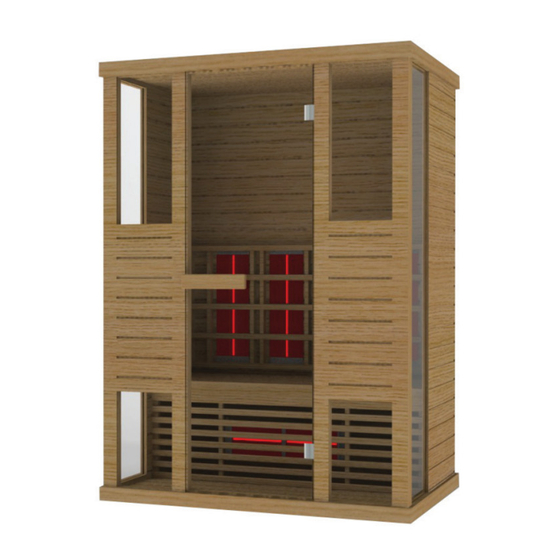
Infrarotkabine
Inhaltsverzeichnis
Verfügbare Sprachen
Verfügbare Sprachen
Quicklinks
Inhaltsverzeichnis

Verwandte Anleitungen für Sentiotec PHÖNIX-L


Inhaltszusammenfassung für Sentiotec PHÖNIX-L
- Seite 1 Benutzerhandbuch Infrarotkabine PHÖNIX-L (1-030-315) 1/11 21.10.2016...
-
Seite 2: Technische Daten
EINLEITUNG Vielen Dank, dass Sie sich für unser Produkt entschieden haben. Bitte lesen Sie dieses Handbuch vor der Montage sorgfältig durch und bewahren Sie es auf. Schreiben Sie sich die Seriennummer der Kabine am Schaltkasten auf, da diese Nummer bei Reparaturen oder der Bestellung von Ersatzteilen erforderlich ist. -
Seite 3: Einzelteile Der Kabine (Abweichungen Möglich)
TEILELISTE Einzelteile der Kabine (Abweichungen möglich) NAME MENGE Bodenplatte (1450 x 1020 x 65 mm) Rückwand (1927 x 1392 x 43 mm) Seitenwand 1 (1927 x 593 x 33 mm) Seitenwand 2 (1927 x 593 x 33 mm) Seitenglas (1896 x 344 x 6 mm) Vorderwand 1 mit Glas (1927 x 409 x 48 mm) Vorderwand 2 mit Glas (1927 x 409 x 48 mm) Deckenplatte (1450 x 1020 x 65 mm) -
Seite 4: Hinweise Zur Montage
Zubehörteile (Abweichungen möglich) Gummistreifen Φ 3 x 16 Φ 4 x 45 Φ 4 x 50 Φ 6 x 60 30 x 20 x 2 10 m 1 Stk. 27 Stk. 16 Stk. 2 Stk. 1 Stk. MONTAGEANLEITUNG Hinweise zur Montage Entfernen Sie die Transportverpackung und prüfen Sie vor der Montage, ob die Infrarotkabine vollständig und in einwandfreiem Zustand geliefert wurde. - Seite 5 MONTAGEANLEITUNG Montageschritte 5/11...
- Seite 6 MONTAGEANLEITUNG Montageschritte Mutter Kappe Hinweis: etwa 20 mm von der Bankplatte entfernt Hinweis: Schließen Sie das Kabel für das Waden- Heizelement 6/11...
- Seite 7 MONTAGEANLEITUNG Montageschritte Sechskantschraube Scharnieroberfläche Gummidichtung Scharnierunterteil Glastür Gummidichtung Griff Glastür Griff Holzabdeckung Gummi- streifen Hinweis: Schließen Sie alle Kabel auf dem Dach der Kabine an. 7/11...
- Seite 8 SCHALTPLAN Stecker Eingangsspannung Leistung Nennstrom Sicherheitsstufe Modell Schaltkasten Waden Bedienfeld Vorder- seite Antenne Farbleuchte AC 12 V/7 W Temperaturfühler (Dach) Rück- seite Hinweis: dient nur als Referenz 8/11...
- Seite 9 SCHALTPLAN ÜBERHITZUNGSSCHUTZ (90 °C) SICHERUNG STRAHLER HAUPTSICHERUNG HAUPTSICHERUNG STRAHLER SICHERUNG LÜFTER SICHERUNG LICHT SICHERUNG VORDERSEITE LÜFTER HEIZELEMENT VORDERSEITE MP3-STROMVERS. (+5 V) LAUTSPRECHER SICHERUNG RÜCKSEITE LAUTSPRECHER ANTENNE HEIZELEMENT RÜCKSEITE TEMP.-FÜHLER (DACH) SICHERUNG WADENHEIZEL. BEDIENFELD WADENHEIZELEMENT SCHALTKASTEN 705M 9/11...
-
Seite 10: Temperatureinstellungen
BEDIENUNGSANLEITUNG Verbinden Sie die Leistungseinheit mit der Wandsteckdose. Auf dem Display beginnt die LED-Anzeige zu blinken. Nun können die Infrarotheizelemente, die Leuchte und die Musikfunktion eingeschaltet werden. 1) Inbetriebnahme Drücken Sie auf , um die Kabine einzuschalten. Die Heizelemente beginnen zu heizen. - Seite 11 SERVICE Gebrauchsanleitung Trinken Sie viel Flüssigkeit vor und nach der Verwendung der Infrarotkabine. Trocknen Sie sich vollständig ab. Die optimale Kabinentemperatur für eine angenehme Sitzung liegt zwischen 35 und 40 °C. Spätestens nach einer Heizzeit von einer Stunde sollte die Kabine ausgeschaltet und eine Heizpause von mindestens 30 Minuten eingelegt werden.
- Seite 12 User’s manual Infrared Cabin PHÖNIX-L (1-030-315) 1/11 2016/10/21...