Herunterladen Inhalt Inhalt Diese Seite drucken

Werbung

Verfügbare Sprachen
  • DE

Verfügbare Sprachen

  • DEUTSCH, seite 1
Montage- und Bedienungsanleitung für Bestell-Nr. 1209
Notice de montage et d'utilisation du
Heimsport-Trainingsgerät
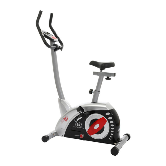
Ergometer
BS 2
D
F
No. de commande 1209
Инструкция по монтажу и эксплуатации
№ заказа 1209
GB
Assembly and exercise instructions for Order No. 1209
NL
Montage- en bedieningshandleiding voor
Bestellnummer 1209
RU
1

Werbung

Inhaltsverzeichnis
loading

Inhaltszusammenfassung für Christopeit BS2

  • Seite 1 Heimsport-Trainingsgerät Ergometer BS 2 Montage- und Bedienungsanleitung für Bestell-Nr. 1209 Assembly and exercise instructions for Order No. 1209 Notice de montage et d’utilisation du Montage- en bedieningshandleiding voor No. de commande 1209 Bestellnummer 1209 Инструкция по монтажу и эксплуатации № заказа 1209...
  • Seite 2: Inhaltsverzeichnis

    Inhaltsübersicht Contents Page 1. Wichtige Empfehlungen und Sicherheitshinweise Seite 2. Einzelteileübersicht Seite 3 - 4 3. Stückliste Seite 5 - 6 4. Montageanleitung mit Explosionsdarstellungen Seite 7 - 9 Sommaire Page 5. Benutzung des Gerätes Seite 10 6. Computeranleitung Seite 11 - 13 7.
  • Seite 5: Stückliste

    Magnet-Brems-System mit ca. 9 kg Schwungmasse • Motor- und Computergesteuerte Widerstandseinstellung 24-stufig regelbar Telefax: +49 (0) 20 51 - 6 06 74 4 • 6 vorgegebene Belastungsprogramme, 4 Herzfrequenzprogramme e-mail: info@christopeit-sport.com (Pulsgesteuert), 1 manuelles Programm • www.christopeit-sport.com 4 individuelle einstellbare Programme, 1 Körperfettprogramm • 1 drehzahlunabhängiges Programm (Vorgabe der Wattleistung von 20 bis 400 Watt in 5-er Schritten einstellbar) •...
  • Seite 6 Abbildungs- Bezeichnung Abmessung Menge Montiert an ET-Nummer Stück Abbildungs Nr. Sitzhalterung 36-1209-06-BT Netzteil 6V=DC/1000mA 36-9808-21-BT Unterlegscheibe 8//16 39-10018-CR Selbstsichernde Mutter 39-9918-CR Tretkurbelscheibe 36-9211-38-BT Flachriemen 430J 42+67 36-1209-07-BT Schraube M6x15 39-10120-SW Federring für M 6 39-9865-SW Sicherungsring 36-9111-39-BT Magnetbügelachse 36-9211-26-BT Magnetbügel 33-9214-14-SI Feder 36-9214-23-BT...
  • Seite 7: Montageanleitung Mit Explosionsdarstellungen

    Montageanleitung Entnehmen Sie alle Einzelteile der Verpackung, legen diese auf den Boden und kontrollieren grob die Vollzähligkeit anhand der Monta- geschritte. Zu beachten ist dabei, dass einige Teile direkt mit dem Grundgestell verbunden sind und vormontiert wurden. Des Weiteren sind auch einige andere Einzelteile schon zu Einheiten Zusammengefügt worden.
  • Seite 8 Schritt 3: Montage des Lenkerstützrohres (12) am Grundrahmen (1). 1. Schieben Sie die Stützrohrverkleidung (11) über das Stützrohr (12). 2. Führen Sie das Lenkerstützrohr (12) mit dem bereits eingelegten Com- puterkabelstrang (3) zum Grundrahmen (1). Verbinden Sie den unten aus dem Lenkerstützrohr (12) ragenden Stecker des Computerkabel- stranges (3) mit dem aus dem Grundgestell (1) ragenden Stecker des Stellmotorkabels (16).
  • Seite 9 Schritt 5: Montage des Lenkers (7) am Stützrohr (12). 1. Führen Sie den Lenker (7) zur geöffneten Lenkeraufnahme am Stützrohr (12) und schließen Sie diese über den Lenker (7). 2. Stecken Sie das Distanzstück (9), die Unterlegscheibe (8) und die Len- kerverkleidung (10) auf die Sterngriffschraube (25) und befestigen Sie damit in gewünschter Position den Lenker (7) am Stützrohr (12).
  • Seite 10: Benutzung Des Gerätes

    Schritt 8: Kontrolle 1. Alle Verschraubungen und Steckverbindungen auf ordnungsgemäße Montage und Funktion prüfen. Die Montage ist hiermit beendet. 2. Wenn alles in Ordnung ist, mit leichten Widerstandseinstellungen mit dem Gerät vertraut machen und die individuellen Einstellungen vorneh- men. Anmerkung: Bitte das Werkzeug-Set und die Anleitung sorgsam aufbewahren, da diese bei ggf.
  • Seite 11: Computeranleitung

    COMPUTER ANLEITUNG „E“ (EINGABE) : Mit der Eingabe - und Bestätigungstaste (E) wechselt man von einem Eingabefeld zum nächsten. Die jeweils angewähl- te Funktion blinkt. Mit der +/- Taste geben Sie die Werte ein und durch erneutes Drücken der „E“ –Taste werden diese bestätigt. Gleichzeitig springt die Blinkanzeige in das nächste Eingabefeld.
  • Seite 12: Programme Einstellung

    PULSOBERGRENZE/BMI/ALTER: Verfügbar in den Programmen 1- 8 Tretwiderstand : Mittels der + / - Taste können Sie jederzeit - in allen Pro- ( nicht in Programm 9 –12). Sobald Sie Ihr Alter eingeben, errechnet der grammen - den Tretwiderstand anpassen. Die Veränderung können Sie an Computer einen Warn-Pulswert, den Sie keinesfalls überschreiten sollten der Balkenhöhe sowie in der Anzeige LEVEL ablesen - je höher die Balken, (Formel: (220 –...
  • Seite 13 Programm 7 (Intervall) Programm 8 (Körper Fett) Programm 9 (Zielp uls) Programm 10 (60% max. Puls.) Programm 11 (70% max. Puls) Programm 12 (80% max. Puls) Programm 13 (Benutzer U1) Programm 14 (Benutzer U1) Programm 15 (Benutzer U1) Programm 16 (Benutzer U1) Programm 17 (Watt-drehzahlunabhängig) Grundsätzlich sind alle ermittelten und angezeigten Werte nicht für Programm 17: Watt-Programm medizinische Auswertungen geeignet. Hier können Sie Ihre individuelle Watt-Vorgabe eingeben. Innerhalb eines gewissen Toleranzbereiches wird der Tretwiderstand automatisch – unab- Programm 1: Manuell hängig von der Trittfrequenz vom Computer nachgeregelt, so dass Sie sich dieses Programm entspricht den Funktionen eines normalen Heimtrainers.
  • Seite 14: Trainingsanleitung

    Faktoren beachtet werden: Weitere Informationen zum Thema Aufwärmübungen, Dehnungsübungen oder allgemeine Gymnastikübungen finden Sie in unserem Downloadbereich 1. Intensität: unter www.christopeit-sport.com Die Stufe der körperlichen Belastung beim Training muß den Punkt der normalen Belastung überschreiten, ohne dabei den Punkt der Atemlosig- 4. Motivation keit und /oder der Erschöpfung zu erreichen. Ein geeigneter Richtwert für Der Schlüssel für ein erfolgreiches Programm ist ein regelmäßiges Training.
  • Seite 15: Important Recommendations And Safety Information

    Contents 1. Summary of Parts Page 3 - 4 2. Important Recommendations and Safety Information Page 15 3. Parts List Page 16 - 17 4. Assembly Instructions With Exploded Diagrams Page 18 - 20 5. Mount, Use & Dismount Page 21 6. Computer instructions Page 22 - 25 7. Training Instructions Page 25...
  • Seite 16: Parts List

    Motor- and Computer-controlled resistance, with 24 manually Telefax: +49 (0) 20 51 - 6 06 74 4 adjustable load steps • 6 installed programs; 4 heart rate programs; 4 individual e-mail: info@christopeit-sport.com programs www.christopeit-sport.com • 1 speed independent program, power control in steps of 5 Watt (20 –...
  • Seite 17 Illustration signation imensions Quantity Attached to ET number illustration No. Seat frame 36-1209-06-BT Adaptor 6V=DC/1000mA 36-9808-21-BT Flat washer 8//16 39-10018-CR Nylon nut 39-9918-CR Belt wheel 36-9211-38-BT Belt 430J 42+67 36-1209-07-BT Bolt M6x15 39-10120-SW Spring washer for M6 39-9865-SW C clip 36-9111-39-BT Magnetic bracket axle 36-9211-26-BT...
  • Seite 18: Assembly Instructions With Exploded Diagrams

    Assembly Instructions Remove all the separate parts from the packaging, lay them on the floor and check roughly that all are there on the base of the assembly steps. Please note that a number of parts have been connected directly to the main frame and preassembled.
  • Seite 19 Step 3: Attach the front post (12) at main frame (1). 1. Push the support cover (11) onto handlebar support (12). 2. Hold the handlebar support (12) with the computer cable (3) against the main frame (1) and connect the plug for the computer cable (3) coming out of the bottom of the handlebar support (12) of the computer with the matching plug for the motor cable (16) coming out of the main frame (1).
  • Seite 20 Step 5: Attach the handlebar (7) at handlebar support (12). 1. Guide the preassembled handlebar unit (7) through the upper part of the handlebar post (12) and close the bracket of handlebar holder. 2. Push the handlebar cover (10) onto the handlebar screw (25) and tighten the handlebar (7) in desired position at the handlebar post (12) with distance tube (9), washer (8) and handlebar screw (25).
  • Seite 21: Mount, Use & Dismount

    Step 8: Checks Check the correct installation and function of all screwed and plug connections. Installation is thereby complete. When everything is in order, familiarise yourself with the machine at a low resistance setting and make your individual adjustments. Note: Please keep the tool set and the instructions in a safe place as these may be required for repairs or spare parts orders becoming necessary later.
  • Seite 22: Computer Instructions

    Computer Instructions D. LEVEL: Indicates the level of loading selected from LEVEL 1 to LEVEL 24. GENDER: Indicates the gender (Male or Female) selected. TIME/HEIGHT/WEIGHT Display: Indicates only 1 value of TIME, HEIGHT, or WEIGHT displayed depending on the programs. RPM/SPEED/KMH Display: Indicates only 1 value of RPM, SPEED, or KMH displayed depending on the programs. DISTANCE/FAT% Display: Indicates only 1 value of DISTANCE or FAT%/ODO displayed depending on the programs. KCAL/WATT/BMR Display: Indicates only one value of KCAL, WATT, or BMR displayed depending on the programs. The monitor is designed for programmable magnetic bikes and introduced with the following categories: TARGET H.R./BMI/AGE Display: Indicates only one value Key Functions of TARGET HEART RATE, BMI, or AGE displayed depending on the About Displays programs. Operating Ranges Things You Should Know Before Exercising Operation Instructions •...
  • Seite 23 C. Programs Selection: • Things You Should Know Before Exercising There are 17 programs with 1 Recovery including 1 Manual A. The values calculated or measured by the computer are for exercise Program, 6 Preset Programs, 1 Body Fat Program, 4 Heart purpose only, not for medical purpose. Rate Control Programs, 4 User Setting Programs, 1 Speed B. The Variables May Need To Change In The Programs: Independent Program, and 1 Pulse Recovery Measuring. Please note that only 1 value of TIME or DISTANCE can be adjusted. D. Program Graph: Both adjustments do not exist at the same time. For example, the value of Each graph shown is the profile of the loading in each interval DISTANCE is „0.0“ while the value of TIME is adjusted to be any number (column). With the value of TIME counting up, each interval is except „00:00“. 3 minutes that all the columns make up 30 minutes. With the value of TIME counting down, each interval is the value of setup TIME divided by 10. For example, if the time value is setup to 40 minutes, each interval will be 40 minutes divided by 10 Programs Variables intervals (40/10=4). Then, each interval will be 4 minutes. The P1 - P7 TIME, DISTANCE, CAL, AGE following graphs are all the profiles in the monitor. P8 GENDER, HEIGHT, WEIGHT, AGE P9 TIME, DISTANCE, CAL, TARGET H.R.
  • Seite 24 Heart Rate Control Programs: E. Body Types: Program 9 to Program 12 are the Heart Rate Control There are 9 body types divided according to the FAT% Programs. In program 9, press „Enter“ key to select TIME, calculated. DISTANCE, and TARGET H.R. Users may setup a target heart Type 1 is from 5% to 9%.
  • Seite 25: Training Instructions

    / or light gymnastic exercises for a period of five to ten minutes. You find further information on the subject warm-up exercises, stretch exer- cises or general gymnastics exercises in our download area under www. christopeit-sport.com 4. Motivation The key to a successful program is regular training. You should set a fixed time and place for each day of training and prepare yourself mentally for the training.
  • Seite 26 Sommaire 1. Aperçu des pièces Page 2. Recommandations importantes et règles de sécurité Page 3. Nomenclature Page 27 - 28 4. Notice de montage avec écorchés Page 29 - 31 5. Monter, utiliser & descendre Page 6. Manuel d’utilisation du calculateur électronique Page 33 - 36 7.
  • Seite 27: Nomenclature

    1 programme indépendant de la vitesse de rotation (par défaut, puissance en watt 1 programme manuel, Mesure des pulsations à la bride, Analyse des lipides Telefax: +49 (0) 20 51 - 6 06 74 4 Alimentation au réseau. e-mail: info@christopeit-sport.com Réglable horizontal et vertical de la selle (verrouillage rapide) L’écran de l’ordinateur dispose de l’affichage digital de données suivantes: www.christopeit-sport.com Durée, vitesse, distance, analyse des lipides, qui correspond plus ou moins à...
  • Seite 28 Schéma Désignation Dimensions Quantité Monté sur Numéro ET n° en mm Unités schéma n° Courroie trapézoidale 430J 42+67 36-1209-07-BT M6x15 39-10120-SW Bague ressort pour M 6 39-9865-SW Bague de sécurité 36-9111-39-BT Axe d’etrier magnétique 36-9211-26-BT Etrier magnétique 33-9214-14-SI Serrage 36-9214-23-BT M5x60 39-10406 Ecrou...
  • Seite 29: Notice De Montage Avec Écorchés

    Notice de montage Sortez toutes les pièces de l’emballage, posez-les sur le sol et contrôlez si rien ne manque en vous basant grossièrement sur la étapes de montage. Il faut tenir compte du fait que certaines pièces ont été reliées au cadre et prémontrés.
  • Seite 30 Etape n° 3: Montage de tube d’appui du guidon (12) sur le cadre de base (1). 1. Glissez le revêtement (11) sur le tube d’appui du guidon (12). 2. Prenez le tube d’appui du guidon (12) avec le câble (3) de l’ordinateur déjà...
  • Seite 31 Etape n° 5: Montage du guidon (7) sur d’appui du guidon (12). 1. Dirigez le guidon (7) vers le logement ouvert du guidon, au niveau du tube support (12) et fermez-le au-dessus du guidon (12). 2. Placez une rondelle (8), une pièce d’écartement (8) et le revêtement de guidon (10) sur la vis à...
  • Seite 32: Monter, Utiliser & Descendre

    Etape n° 8: Contrôle Vérifier si les assemblages et connexions ont été effectués correcte- ment et fonctionnent. Le montage est maintenant terminé. Si tout est en ordre, se familiariser avec l’appareil en effectuant de légers réglages de la résistance et effectuer les réglages individuels. Remarques: Veuillez à...
  • Seite 33: Manuel D'utilisation Du Calculateur Électronique

    Guide d’utilisation de l’ordinateur • Affichages START : Mode du commencement. Toutes les valeurs sont affichées. STOP : Affichage du mode Arrêt. Les données par défaut peuvent être rétablies. PROGRAMME : Affichage du programme engagé 1 –17 (programme 1 – 7: programme ‘fitness’;...
  • Seite 34 Les valeurs établies et affichées ne sont en aucun cas LIMITE SUPERIEURE DES PULSATIONS/BMI/ÂGE Disponible dans les programmes 1 à 8 (mais pas 9 à 12). adaptées à une évaluation médicale. Dès que vous avez introduit votre âge, l’ordinateur calcule une valeur de A.
  • Seite 35: Sélection Du Programme

    A. Sélection du programme: Programme 1 (Manuel) Programme 2 (ascendant - descendant) Programme3 (vallée) Programme 4 (Fitness) Programme 5 (Rampe) Programme 6 (Montagne) Programme 7 (Intervalle) Programme 8 (lipides) Programme 9 (pulsations cibles) Programme 10 (60% max. de puls.) Programme 11 (70% max. de puls.) Programme 12 (80% max.
  • Seite 36: Recommandations Pour L'entraînement

    Vous trouvez les autres informations au sujet exercices pour réchauffer, aux exercices de distension ou les exercices de gymnastique généraux dans notre domaine de téléchargement sous le www.christopeit-sport.com Les facteurs ci-après doivent être pris en compte pour la détermination de l’entraînement indispensable afin d’améliorer concrètement son physique...
  • Seite 37: Belangrijke Aanbevelingen En Veiligheidsinstructies

    Inhoudsopgave 1. Overzicht van de losse delen pagina 3 - 4 2. Belangrijke aanbevelingen en veiligheidsinstructies pagina 37 3. Stuklijst pagina 38 - 39 4. Montagehandleiding met explosietekeningen pagina 40 - 42 5. Opstappen, Gebruiken & Afstappen pagina 43 6. Handleiding bij de computer pagina 44 - 47 7.
  • Seite 38: Stuklijst

    Adapter, Fitness-Test aanduiding, Telefax: +49 (0) 20 51 - 6 06 74 4 Stelvoeten om waterpas te zetten transportrollen Horizontaal en vertikaal verstelbare zadelpositie e-mail: info@christopeit-sport.com Bedieningsvriendelijke computer met gelijktijdige aanduiding van; tijd, snelheid, afstand, ca. calorieverbruik, lichaamsvet analyse, www.christopeit-sport.com pedaalomwentelingen, Wattage, polsslagfrequentie Instelbaarheid van de grenswaarden;...
  • Seite 39 Afbeeldings- Beschrijving Afmetingen Aantal Gemonteerd aan ET-nummer stuks afbeeldingsnr. Veerring voor M 6 39-9865-SW Vastzetring 36-9111-39-BT Magneetbeugelas 36-9211-26-BT Magneetbeugel 33-9214-14-SI Veer 36-9214-23-BT Schroef M5x60 39-10406 Moer 39-10012 Kogellager 6003 39-9947 Vastzetring 36-9805-32-BT Spanrol 36-9211-28-BT Glijdlager 36-9211-14-B Schroef M8x20 39-10095-CR Spanrolbeugel 33-9211-11-SI Veer 36-9211-37-B...
  • Seite 40: Montagehandleiding Met Explosietekeningen

    Montagehandleiding Neem alle losse onderdelen uit de verpakking, leg deze op de grond en bruto controleer aan de hand van de montageen staps of alle onderdelen aanwezig zijn. Hierbij moet er op worden gelet dat een aantal onderdelen rechtstreeks met het onderstel zijn verbonden en voorgemonteerd zijn.
  • Seite 41 Stap 3: Montage van de stuurbuis (12) aan het onderstel (1). 1. Plaats de stuurbuis bekleiding (11) aan het stuurbuis (12). 2. Pak de stuurbuis (12) waarin de computerkabel (3) al geplaatst is. Verbind de stekker voor de computerkabel (3) die uit de onderkant van de stuurbuis (12) steekt met de bijbehorende stekker voor de stelmotorkabel (16) die uit het onderstel (1) steekt.
  • Seite 42 Stap 5: Montage van de stuur (7) aan de stuurbuis (12). 1. Voer het stuur (7) door de geopende stuurhouder op de stuurbuis (12) en sluit u deze over het stuur (7). 2. Plaatst u een Afstandstuk (9), de tussenring (8) en den stuur bekleiding (10) op de stuurgrep schroef (10) en hiermee bevestigd u het stuur (7) in de gewenste positie op stuurbuis (12).
  • Seite 43: Opstappen, Gebruiken & Afstappen

    Stap 8: Controle: Alle schroef- en stekkerverbindingen op een correcte montage en juiste werking controleren. Daarmee is de montage beëindigd. Wanneer alles in orde is, met lichte weerstandsinstellingen vertrouwd raken met het apparaat en de individuele instellingen vastzetten. Opmerking: De gereedschapsset en de gebruiksaanwijzing a.u.b. zorgvuldig bewaren, omdat u ze wellicht later voor een reparatie of het bestellen van reserveo- nderdelen nodig heeft.
  • Seite 44: Handleiding Bij De Computer

    Computerhandleiding • Toetsen In totaal 6 toetsen: START/STOP(S) , INVOER (E), FUNCTIE (F), OMHOOG (+), OMLAAG (-), en TEST (Test) „START/STOP“: start van de training of onderbreking van de training in het gekozen programma. In de modus „STOP“ is het STOP-display verlicht. De computer begint pas te tellen wanneer voordien de toets „START/ STOP“...
  • Seite 45 KCAL/WATT/BMR: door middel van de gemiddelde waarden berekent de hogere balken=hogere trapweerstand computer de Calorieën, die in KCAL aangegeven worden. Om de bindende lagere balken= lagere trapweerstand maateenheid voor energie „Joule“ in de algemeen gebruikelijke vermelding elk balkensegment houdt 3 waarden in „Calorieën“...
  • Seite 46 A. Programmakeuze: Programma 1 (handmatig) Programma 2 (omhoog - omlaag) Programma 3 (dal) Programma 4 (fitness) Programma 5 (platform) Programma 6 (berg) Programma 7 (interval) Programma 8 (lichaamsvet) Programma 9 (beoogde polsslag) Programma 10 (60% max. polsslag) Programma 11 (70% max. polsslag) Programma 12 (80% max. polsslag) Programma 13 (gebruiker U 1) Programma 14 (gebruiker U 2) Programma 15 (gebruiker U 3)
  • Seite 47: Trainingshandleiding

    „fitnesscijfer“ door te voeren. Trainingshandleiding of algemene gymnastische oefenen in onze downloadarea onder www. christopeit-sport.com De onderstaande factoren moeten in acht worden genomen bij het bepalen 4. Motivatie van de benodigde training voor het bereiken van een merkbare verbetering De sleutel tot een succesvol programma is een regelmatige training.
  • Seite 48: Обзор Содержания

    Обзор содержания Важные рекомендации и указания по безопасности ctp. 2. Обзор отдельных деталей стр. 3 - 4 3. Спецификация стр. 49 - 50 4. Руководство по сборке с отдельными иллюстрациями стр. 51 - 53 5. Пользование тренажером стр. 6. Руководство по использованию компьютера стр.
  • Seite 49 Измерение пульса датчиками на рукоятках, транспортировочные ролики впереди, блок питания, фитнес-тест Telefax: +49 (0) 20 51 - 6 06 74 4 Г оризонтальное и вертикальное регулирование седла, регулировка наклона руля и седла e-mail: info@christopeit-sport.com Компьютер с одновременной индикацией следующих параметров: время, скорость, дистанция, прибл. расход калорий, процентное содержание жира, частота вращения www.christopeit-sport.com педалей, нагрузка...
  • Seite 50 № Наименование Размеры в мм Кол-во Монтируется на № ЕТ-№ картинки штук Диск шатуна 36-9211-38-BT Плоский ремень 430J 42+67 36-1209-07-BT Болт M6x15 39-10120-SW Пружинящее кольцо для M 6 39-9865-SW Стопорное кольцо 36-9111-39-BT Крепление хомута магнита 36-9211-26-BT Хомут магнита 33-9214-14-SI Пружина 36-9214-23-BT Болт...
  • Seite 51: Руководство По Монтажу

    Руководство по монтажу Пожалуйста, выньте все отдельные части из коробки и проверьте их на комплектность в соответствии со спецификацией. Примите во внимание, что некоторые части предварительно смонтированы. Шаг 1: Монтаж ножек (20+27) на основную раму (1). 1. Смонтируйте переднюю ножку (20) с транспортировочными роликами (18) на...
  • Seite 52 Шаг 3: Монтаж опорной трубы руля (12) на основную раму (1). 1. Вставьте манжету Обшивка опорной трубы (11) на опорную трубу седла (12). 2. Возьмите опорную трубу руля (12) с предварительно смонтированным соединительным кабелем (3). Соедините штекер компьютерного кабеля (3), выходящий из опорной трубы руля (12), со Кабель серводвигателя...
  • Seite 53 Шаг 5: Монтаж руля (7) на опорную трубу руля (12). 1. Подведите руль (7) к открытому креплению руля на опорной трубу руля (1) и закройте его над рулем (7). Вставьте оболочки рукоятки на руль (7). 2. Наденьте подкладную шайбу (9), кожух руля (10) и подкладные шайбы...
  • Seite 54 Шаг 8: Контроль: Проверьте все соединения на правильность сборки и проведите проверку функциональности. При этом монтаж считается законченым. Если все в порядке, проведите пробную тренировку при маленькой нагрузке, и индивидуально настройте тренажер. Замечание: Пожалуйста, сохраняйте набор инструментов для последующих возможных ремонтов и инструкцию по монтажу для возможных заказов запасных...
  • Seite 55: Функциональные Клавиши

    Описание компьютера ИНДИКАЦИЯ START/СТАРТ: Индикация старт модуса. Все имеющиеся данные показываются на дисплее. STOP/СТОП: Индикация стоп модуса. Возможен ввод данных. PROGRAM/ПРОГРАММА : Индикация встроенных программы от 1-17 (программы 1–7 - фитнес- программы, программа 8 – программа измерения процентного содержания жира, программы 9-12 – пульсозависимые программы, программы...
  • Seite 56 TARGET HR/BMI/AGE / ВЕРХНЕЕ ОГРАНИЧЕНИЕ ПУЛЬСА/BMI/ клавишу „S“. В противном случае не будет показываться частота пульса, ВОЗРАСТ: нагрузка в ваттах и т.д Функция доступна только в программах 1-8 и не доступна в программах 9-12. После ввода возраста компьютер расчитывает верхний допустимый Возможные...
  • Seite 57: Выбор Программ

    A. Выбор программ: Программа 1 Ручная настройка Программа 2 Вверх-вниз Программа 3 Ущелье Программа 4 Фитнес Программа 5 Рампа Программа 6 Гора Программа 7 Интервал Программа 8 Сжигание жира Программа 9 целевой пульс Программа 10 60% макс. пульс Программа 11 70% макс. пульс Программа 12 80% макс. пульс Программа...
  • Seite 58 Компьютер с учетом определенных допусков и независимо от частоты вращения педалей удерживает эту нагрузку в заданном вами пределе. СПИСОК ВОЗМОЖНЫХ НЕИСПРАВНОСТЕЙ: После каждого нового старта компьютер проводит быстрый тест на функциональность. При обнаружении несоответствия имеются три сигнала неисправности: E 1 Этот сигнал, сопровождающийся звуком, появляется, если есть неисправности...
  • Seite 59 упражнений. Вы находите следующие сведения о теме Упражнения на подогреве, упражнениях на растяжение мышц или общие упражнения гимнастики в нашей области загрузки под www.christopeit-sport.com Мотивация Ключевым моментом успеха программы являются регулярные тренировки. Вам следует установить конкретное время и место на...
  • Seite 60 Bei Reklamationen, notwendigen Ersatzteilbestellungen oder © by Top-Sports Gilles GmbH Reparaturen wenden Sie sich bitte an unsere Service Abteilung. D-42551 Velbert (Germany) Service: Top-Sports Gilles GmbH Tel.: +49 (0)2051/6067-0 Friedrichstrasse 55 info@christopeit-sport.com Fax: +49 (0)2051/6067-44 D - 42551 Velbert http://www.christopeit-sport.com...

Inhaltsverzeichnis