Inhaltsverzeichnis
Werbung
Verfügbare Sprachen
Verfügbare Sprachen
Quicklinks
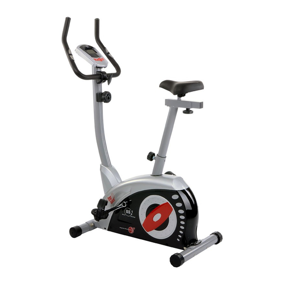
Heimsport-Trainingsgerät
BS 1
D
GB
Montage- und Bedienungsanleitung
Assembly and exercise instructions
for Order No. 1208
für Bestell-Nr. 1208
F
NL
Notice de montage et d'utilisation du
Montage- en bedieningshandleiding voor
No. de commande 1208
Bestellnummer 1208
RU
Инструкция по монтажу и эксплуатации
№ заказа 1208
1
Werbung
Kapitel
Inhaltsverzeichnis

Verwandte Anleitungen für Christopeit BS1


Inhaltszusammenfassung für Christopeit BS1
- Seite 1 Heimsport-Trainingsgerät BS 1 Montage- und Bedienungsanleitung Assembly and exercise instructions for Order No. 1208 für Bestell-Nr. 1208 Notice de montage et d’utilisation du Montage- en bedieningshandleiding voor No. de commande 1208 Bestellnummer 1208 Инструкция по монтажу и эксплуатации № заказа 1208...
-
Seite 2: Inhaltsverzeichnis
Inhaltsübersicht Contents Page 1. Wichtige Empfehlungen und Sicherheitshinweise Seite 2 2. Einzelteileübersicht Seite 3 - 4 3. Stückliste Seite 5 - 6 4. Montageanleitung mit Explosionsdarstellungen Seite 7 - 9 Sommaire Page 5. Benutzung des Gerätes Seite 10 6. Computeranleitung Seite 11 7. Trainingsanleitung Seite 12 Inhoudsopgave Pagina 31 Sehr geehrte Kundin, sehr geehrter Kunde Wir gratulieren Ihnen zum Kauf dieses Heimsport-Trainingsgerätes und... -
Seite 5: Stückliste
Telefon: +49 (0) 20 51 - 6 06 70 • 8-stufige manuelle Widerstandseinstellung • Handpulsmessung Telefax: +49 (0) 20 51 - 6 06 74 4 • Horizontal und vertikal verstellbarer Sattel e-mail: info@christopeit-sport.com (Schnellverschluss) www.christopeit-sport.com • Sattel und Lenker neigungsverstellbar • Niveau Boden Höhenausgleich •... - Seite 6 Abbildungs- Bezeichnung Abmessung Menge Montiert an ET-Nummer Stück Abbildungs Nr. Widerstandsregulierung 12+39 36-9211-10-BT Seilzug 38+48 36-9211-11-BT Unterlegscheibe 8//16 39-10018-CR Selbstsichernde Mutter 39-9918-CR Tretkurbelscheibe 36-9211-38-BT Flachriemen 430J 42+67 36-1209-07-BT Schraube M6x15 39-10120-SW Federring für M 6 39-9865-SW Sicherungsring 36-9111-39-BT Magnetbügelachse 36-9211-26-BT Magnetbügel 33-9214-14-SI Feder...
-
Seite 7: Montageanleitung Mit Explosionsdarstellungen
Montageanleitung Entnehmen Sie alle Einzelteile der Verpackung, legen diese auf den Boden und kontrollieren grob die Vollzähligkeit anhand der Monta- geschritte. Zu beachten ist dabei, dass einige Teile direkt mit dem Grundgestell verbunden sind und vormontiert wurden. Des Weiteren sind auch einige andere Einzelteile schon zu Einheiten Zusammengefügt worden. - Seite 8 Schritt 3: Montage des Lenkerstützrohres (12) am Grundrahmen (1). 1. Schieben Sie die Stützrohrverkleidung (11) über das Stützrohr (12). 2. Führen Sie das Lenkerstützrohr (12) mit dem bereits eingelegten Com- puterkabelstrang (3) zum Grundrahmen (1). Verbinden Sie den unten aus dem Lenkerstützrohr (12) ragenden Stecker des Computerkabel- stranges (3) mit dem aus dem Grundgestell (1) ragenden Stecker des Sensorkabels (16).
- Seite 9 Schritt 5: Montage des Lenkers (7) am Stützrohr (12). 1. Führen Sie den Lenker (7) zur geöffneten Lenkeraufnahme am Stützrohr (12) und schließen Sie diese über den Lenker (7). 2. Stecken Sie das Distanzstück (9), die Unterlegscheibe (8) und die Len- kerverkleidung (10) auf die Sterngriffschraube (25) und befestigen Sie damit in gewünschter Position den Lenker (7) am Stützrohr (12).
-
Seite 10: Benutzung Des Gerätes
Schritt 7: Kontrolle 1. Alle Verschraubungen und Steckverbindungen auf ordnungsgemäße Montage und Funktion prüfen. Die Montage ist hiermit beendet. 2. Wenn alles in Ordnung ist, mit leichten Widerstandseinstellungen mit dem Gerät vertraut machen und die individuellen Einstellungen vorneh- men. Anmerkung: Bitte das Werkzeug-Set und die Anleitung sorgsam aufbewahren, da diese bei ggf. -
Seite 11: Computeranleitung
Computeranleitung für 1208 Der mitgelieferte Computer bietet den größten Trainingskomfort. Jeder Achtung: trainingsrelevante Wert wird in einem entsprechenden Sichtfenster angezeigt. Zur Pulsmessung müssen die beiden Kontaktflächen der Pulsmessgriff- Einheit (4) mit beiden Händen gleichzeitig gegriffen werden. Dabei sollten Vom Trainingsbeginn an werden die benötigte Zeit, die aktuelle sich die Kontaktflächen mittig in der Handinnenfläche befinden. -
Seite 12: Trainingsanleitung
Muskelkater oder Zerrungen vorzubeugen, muß nach der „Trainings-Phase“ noch die „Abkühl-Phase“ eingehalten werden. In dieser sollten, fünf bis zehn Minuten lang, Dehnungsübungen und/oder leichte gymnastische Übungen durchgeführt werden. Weitere Informationen zum Thema Aufwärmübungen, Dehnungsübungen oder allgemeine Gymnastikübungen finden Sie in unserem Downloadbereich unter www.christopeit-sport.com Garantiebestimmungen Die Garantieleistung gilt nur für Material oder Fabrikationsfehler. Bei Ver- Die Garantie beginnt mit dem Rechnungs- bzw. Auslieferdatum und beträgt schleißteilen oder Beschädigungen durch missbräuchliche oder unsach- 24 Monate. gemäße Behandlung, Gewaltanwendung und Eingriffen die ohne vorherige Absprache mit unserer Service Abteilung vorgenommen werden, erlischt Während der Garantiezeit werden eventuelle Mängel kostenlos beseitigt.