Harvia XENIO COMBI Montage- Und Gebrauchsanleitung
Steuergerät
Inhaltsverzeichnis
Inhaltsverzeichnis

Verwandte Anleitungen für Harvia XENIO COMBI


Inhaltszusammenfassung für Harvia XENIO COMBI
- Seite 1 HARVIA XENIO COMBI Control unit Steuergerät 09072015/ZVR-851...
-
Seite 2: Inhaltsverzeichnis
Ofens bzw. des Steuergeräts oder der für die War- tung der Anlagen zuständigen Person auszuhändi- gen. CONTROL UNIT HARVIA XENIO COMBI (CX110C) Control unit's purpose of use: the control unit is STEUERGERÄT HARVIA XENIO COMBI (CX110C) meant for controlling the functions of a sauna Verwendungszweck des Steuergeräts: Das... -
Seite 3: Harvia Xenio Combi
1. HARVIA XENIO COMBI 1.1. General 1.1. Allgemeines The purpose of the Harvia Xenio Combi control unit Der Zweck des Steuergeräts Harvia Xenio Combi is to control an electric sauna heater and steamer, liegt darin, einen elektrischen Saunaofen nebst Ver-... -
Seite 4: Troubleshooting
Weight 175 g with leads (ca 4 m) gestattet (22 kΩ/T=25 °C). • Dimensions: 51 mm x 73 mm x 27 mm Der Feuchtigkeitsfühler WX325 misst Tempera- • • tur und relative Luftfeuchtigkeit. Gewicht 175 g mit Leitungen (ca 4 m) •... -
Seite 5: Instructions For Use
2. INSTRUCTIONS FOR USE 2. BEDIENUNGSANLEITUNG 2.1. Using the Heater and the Steamer 2.1. Verwendung des Ofens und des Verdampfers When the control unit is connected to the power Wenn das Steuergerät an die Stromversorgung an- supply and the main switch (see figure 1) is geschlossen ist und der Hauptschalter (siehe Ab- switched on, the control unit is in standby mode bildung 1) betätigt wird, befindet sich das Steuer-... -
Seite 6: Heater And/Or Steamer Off
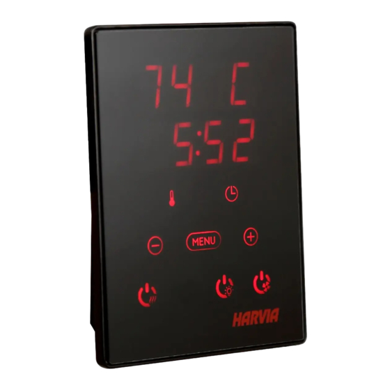
2.1.2. Heater and/or Steamer Off 2.1.2. Ofen und/oder Verdampfer ausschalten The heater and/or steamer turn off and the control Ofen und/oder Verdampfer werden ausgeschaltet unit switches to standby-mode when und das Steuergerät schaltet in den Standby-Modus the I/O button is pressed um, wenn •... - Seite 7 BASIC SETTINGS/GRUNDEINSTELLUNGEN Basic mode (heater and steamer on) Basis-Modus (Ofen und Verdampfer ein) The top row shows the sauna room Die obere Zeile zeigt die Temperatur in temperature. The bottom row shows the der Saunakabine an. Die untere Zeile zeigt humidity level (or remaining on-time, if the die Luftfeuchtigkeit an (oder bei nicht steamer is not activated).
- Seite 8 ADDITIONAL SETTINGS/WEITERE EINSTELLUNGEN Control unit standby Standby des Steuergeräts I/O buttons’ background lights glow on the Die Kontrollleuchten der I/O-Tasten leuchten auf control panel. dem Bedienfeld. Open the settings menu by simultaneously Öffnen Sie das Einstellungsmenü, indem Sie pressing the locations of the buttons –, gleichzeitig die Taste -, MENU und + drücken MENU and + (see figure 2).
-
Seite 9: Instructions For Installation
3. INSTRUCTIONS FOR INSTALLATION 3. INSTALLATIONSANLEITUNG The electrical connections of the control unit Die elektrischen Anschlüsse des Steuergeräts dür- may only be made by an authorised, professional fen nur von einem autorisierten, geschulten Elektri- electrician and in accordance with the current ker unter Beachtung der aktuell gültigen Vorschrif- regulations. -
Seite 10: Installing The Power Unit
be at the minimum safety distance from the heater der Sauna montiert, muss es in der Saunawand auf and at a maximum height of one metre from the max. 1 m Höhe eingelassen werden. Eine aufge- floor. Figure 4. setzte Montage ist nicht erlaubt. Auch der Mindest- Conductor tubing (ø... -
Seite 11: Power Unit Fuse Faults
3.2.2. Power Unit Fuse Faults 3.2.2. Sicherungsdefekte der Leistungseinheit Replace a blown fuse by a new one with the same Ersetzen Sie eine defekte Sicherung gegen eine Si- value. The placement of the fuses in the power unit cherung desselben Werts. Die Position der Siche- is shown in figures 6 and 7. -
Seite 13: Installing The Temperature Sensor
3.3. Installing the Temperature Sensor 3.3. Montage des Temperaturfühlers Check the correct location for the temperature sen- Überprüfen Sie den richtigen Standort des Tempe- sor from the heater’s instructions for installation raturfühlers nach den Gebrauchs- und Montagean- and use. leitungen des Ofens. Wall-mounted heaters (see figure 8) Öfen mit Wandbefestigung (Abbildung 8) Fasten the temperature sensor on the wall... -
Seite 14: Installing The Humidity Sensor
3.4. Installing the Humidity Sensor 3.4. Montage des Feuchtigkeitsfühlers Fasten the humidity sensor on the wall as far from Bringen Sie den Feuchtigkeitsfühler so weit wie the heater as possible and at a distance of 500–700 möglich vom Ofen entfernt an der Wand an, in ei- mm from the ceiling. -
Seite 15: Resetting The Overheat Protector
WX232 360° 180° Figure 11. Reset button of the overheat protector Abbildung 11. Rückstellknopf des Überhitzungsschutzes Figure 10. Sensor’s minimum distance from an air vent Abbildung 10. Mindestabstand des Fühlers zu Luftschlitzen 3.5. Resetting the Overheat Protector 3.5. Zurückstellen der Überhitzungsschutzes The sensor box ( ) contains a temperature Das Fühlergehäuse (WX232) enthält einen Tempe-...