PeakTech 2280 Bedienungsanleitung

Verwandte Anleitungen für PeakTech 2280


Inhaltszusammenfassung für PeakTech 2280
- Seite 1 2275 / 2280 Bedienungsanleitung / Operation manual Programmierbare elektronische DC-Last / DC Programmable Electronic Load...
-
Seite 3: Inhaltsverzeichnis
INHALTSVERZEICHNIS / TABLE OF CONTENTS 1. SICHERHEITSHINWEISE ZUM BETRIEB DES GERÄTES .............. 6 ........................7 EINIGUNG DES ERÄTES 2. EINFÜHRUNG ........................... 7 2.1 M ........................... 7 ERKMALE 2.2 Z ............................. 7 UBEHÖR 3. TECHNISCHE DATEN ........................8 3.1 K ..........................8 ENNDATEN 3.2 A ........................ - Seite 4 6.7.1 C (CONT) ....................30 ONTINUOUS ODUS 6.7.2 P (PULS) ......................31 ULSE ODUS 6.7.3 T (TRIG) ......................31 RIGGER ODUS 6.8 S ......................31 CHUTZ IM EHLERFALL ANHANG A – REMOTE-SENSE-SCHNITTSTELLE UND EXTERNER TRIGGER ......33 A1 Remote Sense ........................33 A2 Externer Trigger ........................
- Seite 5 6. OPERATION ........................... 58 6.1 C (CC M ) ................... 58 ONST URRENT 6.2 C (CV M ) .................... 58 ONST OLTAGE 6.3 C (CP M ) ....................59 ONST OWER 6.4 C (CR M ) ..................60 ONST ESISTANCE 6.5 B ........................
-
Seite 6: Sicherheitshinweise Zum Betrieb Des Gerätes
1. Sicherheitshinweise zum Betrieb des Gerätes Dieses Gerät erfüllt die EU-Bestimmungen 2014/30/EU (elektromagnetische Kompatibilität) und 2014/35/EU (Niederspannung) entsprechend der Festlegung im Nachtrag 2004/22/EG (CE-Zeichen). Zur Betriebssicherheit des Gerätes und zur Vermeidung von schweren Verletzungen durch Strom- oder Spannungsüberschläge bzw. Kurzschlüsse sind nachfolgend aufgeführte Sicherheitshinweise zum Betrieb des Gerätes unbedingt zu beachten. -
Seite 7: Reinigung Des Gerätes
Bereichen heutiger Elektronik samt batteriebetriebenen Systemen – sowohl in der Produktion wie auch in der Forschung und Entwicklung – ihre Anwendung finden. Mit den maximal bemessenen Leistungen von 150W (2275) bzw. 300W (2280), max. Eingangsspannung von 360V und Auflösungen von 1mV/1mA/1mΩ/1mW in unteren Messbereichen werden diese Geräte den meisten Anforderungen gerecht. -
Seite 8: Technische Daten
3. Technische Daten 3.1 Kenndaten Modell 2275 2280 Eingangsspannung 0 V ~ 360 V 0 V ~ 360 V Spezifikationen Eingangsstrom 1 mA ~ 30 A 1 mA ~ 30 A Eingangsleistung 150 W 300 W Genauigkeit Messbereich Auflösung 0 V … 9.999 V ±... -
Seite 9: Netzversorgung
220/110 (1±10%)V AC, 50 Hz/60 Hz (1±5%) Abgesichert durch eine 1A-Sicherung. 3.4 Maße 310mm × 225mm × 100mm 3.5 Gewicht Ca. 5.5 kg (P 2275) / 6.0 kg (P 2280) 4. Vorder- und Rückseite des Gerätes 4.1 Vorderseite Nummer Name... -
Seite 10: Rückseite
4.2 Rückseite Nummer Name Beschreibung 6, 9 Ventilationsöffnungen Öffnungen nicht verdecken 110V/220V AC Umschalter Bitte beachten Sie die richtige Stellung entspechend der Netzspannung in Ihrer Region Remote Sense und Trigger siehe Anhang A für Pin-Belegung RS-232-Schnittselle Kaltgerätebuchse mit 1A-Sicherung Sicherungshalter... -
Seite 11: Tastenfeld
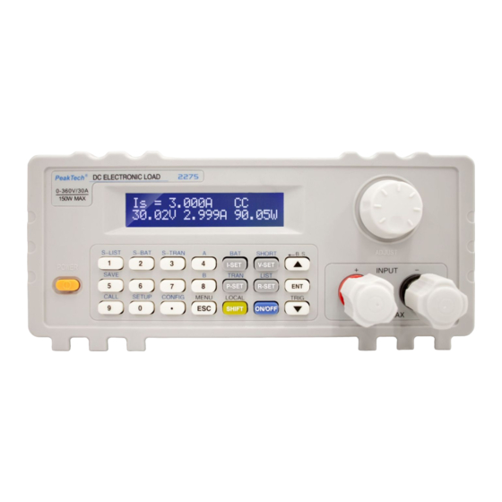
4.3 Tastenfeld Ziffernblock 1, 2, 3, 4, 5, 6, 7, 8, 9, 0, . Basismodi I-SET, V-SET, P-SET, R-SET On-/Off-Taste Schaltet den Eingang ein und aus ESC, ENT, ▲, ▼ Menü-Tasten S-LIST, S-BAT, S-TRAN, SAVE, CALL, SETUP, Tasten-Funktionen nach Betätigen der SHIFT-Taste CONFIG, BAT, SHORT, TRAN, A, B Abgeleitete Funktionstasten... - Seite 12 Erklärung zum oberen Bild: Beschreibung Anmerkungen Is: konst. Strom Vs: konst. Spannung Ps: konst. Leistung Modus Rs: konst. Widerstand Short: Kurzschlusstest Battery: Batterietest Transient: dynamischer Test OFF: Last-Ausgang aus RUN: Last-Ausgang an °°°°: Statuswechsel/Warten UREG: Last nicht im konstanten Zustand CC: konst.
- Seite 13 ↑ SHIFT-Taste gedrückt Testensperre Bedienung Fernsteuerung Spannung an den Polklemmen oder Sense- Eingangsspannung Eingang Stromverbrauch Aktueller Stromverbrauch Gilt nicht unter Batterietest/dyn. Test Aktuelle Leistung Leistung Reverse Voltage!!!: Verpolung Sonst. Wichtige Alarm-Infos Exceed Voltage!!!: Überspannung Autom. Lastabschaltung Over Hot!!!: Temperatur zu hoch Autom.
-
Seite 14: Menü
5. Menü 5.1 Allgemein Das Menü beinhaltet alle Arbeitsmodi und Einstellungen des Gerätes. Beim Drücken der 【MENU】- Taste gelangen Sie in das Menü. Sie können auch direkt das 1. Untermenü über die 【SHIFT】-Taste aufrufen. Die Navigation erfolgt über die Tasten 【▲】und 【▼】oder über den Drehknopf. Um einen Punkt auszuwählen, drücken Sie die Taste 【ENT】, über die Taste 【ESC】verlassen Sie wieder den ausgewählten Punkt. - Seite 15 Exit Remote Sense 【Ent】: Eingabe Max Current 【Ent】: Eingabe Max Voltage 【Ent】: Eingabe Max Power On Voltage 【Ent】: Eingabe Load Setup Off Voltage 【Ent】: Eingabe Auto Off 【Ent】: Eingabe (Zeit in Sekunden) InVolt CR-Mode InCurrent Exit 【Ent】: Eingabe Discharge Current 【Ent】: Eingabe Min Voltage Battery Test Set...
- Seite 16 Step Number Nummer 00~14 AUTO Step Mode TRIG Repeat ConstCurr ConstVolt ConstPower List Load ConstRes Short (für Kurzschluss) List Test Set Open (für off. Stromkreis) 【Ent】: Eingabe Level 【Ent】: Eingabe Delay Step00~14 InVoit (für Spannungsvergleich) Compare InCurr (für Stromvergleich) InPower (für Leistungsvergleich) 【Ent】: Eingabe Limit Low...
-
Seite 17: Short Cut Menü
【Esc】 : abbrechen Copy To Nest 【Ent】:kopieren Exit Nummer 0 ~ 9 Save File 【Ent】: ausgewählte Datei speichern Nummer 0 ~ 9 Recall File 【Ent】: ausgewählte Datei laden Exit 【Ent】: Menü verlassen 5.3 Short Cut Menü Drücken Sie die 【 SHIFT 】... -
Seite 18: Hauptmenü (Main Menu)
5.4 Hauptmenü (Main Menu) Das Hauptmenü enthält alle im Punkt 5.2 erwähnten Untermenüs. Im Folgenden werden diese ausführlicher beschrieben. MAIN MENU: System Config deutet an, dass eine Auswahl mit den Tasten 【▲】 【▼】möglich Hinweis: Das Symbol ist. 5.4.1 System Config Dieses Untermenü... -
Seite 19: Load Setup
Communication Mode Die RS232C-Schnittstelle erlaubt eine Kommunikation der PC-Software mit mehreren Geräten. Es wird in allen Fällen ein 8-Bit-Übertragungsmodus verwendet. Separator: Einzelgerät-Modus Multipler: Mehrgeräte-Modus Bitte beachten Sie in dem Zusammenhang, dass die Last im Einzelgerät-Modus nicht über eine explizite Adresse angesprochen werden kann, wie es im Mehrgeräte-Modus der Fall ist (s. dazu Abschnitt „Local Address“). - Seite 20 Remote Sense Da die Abtastung der Spannung die Genauigkeit der übrigen Berechnungen beeinträchtigt, möchte man die Spannung so nah an den Polen der Quelle wie möglich messen. Dies wird besonders bei größeren Strömen deutlich, wenn die Ausgangsspannung der Quelle kleiner wird und ein Großteil davon an den Leitungen zu der Last abfällt.
-
Seite 21: Batterietest (Battery Test Set)
On Voltage Der Punkt "On Voltage" stellt eine Mindestgrenze für eine Spannung dar, die anliegen muss, damit sich der Eingang der Last aktiviert. Sollte die anliegende Spannung unter dieser Grenze liegen, ist der Eingang nicht aktiv und es erscheint die Meldung "。。。。", was auf den Zustand "Warten" hindeuten soll. -
Seite 22: Dynamischer Test (Tran Test Set)
Min Voltage Mit „Min Voltage“ setzen Sie den End-Spannungswert Ihrer Batterie, bei dessem Unterschreiten der Test angehalten werden soll. Auf der Anzeige erscheint am Ende des Tests die Entladezeit und die Kapazität in Ah. Wählen Sie den Punkt „Min Voltage“ aus, drücken Sie 【ENT】und geben Sie den gewünschten Spannungswert ein. -
Seite 23: Benutzerdefinierte Anweisungsliste (List Test Set)
Tran Mode Die elektronische Last besitzt im dynamischen Modus drei Steuerungsmodi, um mit oben genannten Werten von A, B zu arbeiten. CONT: Continuous Mode. Schaltet kontinuierlich zwischen Level A und Level B mit den entsprechenden Werten von Width A, Width B. PULS: Pulse Mode. -
Seite 24: Save File
Step XX XX steht hier für eine Nummer der Anweisung (00 – 14). Drücken Sie 【ENT】, um das Untermenü aufzurufen: List Load Setzt einen der Last-Modi (CC, CV, CP, CR, Short, Open) für die Anweisung XX. Level Der Wert bezogen auf den Last-Modus. Bei Short oder Open ohne Bedeutung, sonst jeweils in der Einheit A (bei CC), V (bei CV) usw. -
Seite 25: Recall File
5.4.7 Recall File Laden Sie hier manuell Ihre Einstellungs-Dateien. Ein Status „N“ deutet darauf hin, dass keine Datei unter der Nummer existiert. Drücken Sie 【ENT】, um die ausgewählte Datei zu laden. 5.4.8 Exit Drücken Sie 【ENT】 oder 【ESC】, um das Hauptmenü zu verlassen. -
Seite 26: Betrieb
6. Betrieb Dieses Kapitel beschreibt die Anwendung der elektronischen Lasten P 2275 und P 2280 und deren Arbeitsmodi. 6.1 Konstantstrommodus (CC Mode) Im Konstanstrommodus versucht die Last stets den Strom konstant zu halten, auch wenn sich zwischendurch die Spannung an den Polklemmen (oder ggf. Sense-Eingang) ändert. -
Seite 27: Konstantleistungsmodus (Cp Mode)
Befinden Sie sich gerade in einem anderen Modus, drücken Sie 【V-SET】,um den Konstantspannungsmodus auszuwählen. Drücken Sie sodann 【ON/OFF】, um die Last zu aktivieren/deaktivieren. Ist die Last deaktiviert, können Sie den angezeigten Sollwert in Volt mit dem Drehknopf verändern. Drücken Sie nochmal【V-SET】, um den Sollwert über den Ziffernblock einzugeben. Hinweis: Ist die Spannung an den Polklemmen/Sense-Eingang niedriger als der eingestellte Sollwert, hat der CV-Modus keine Funktion. -
Seite 28: Konstantwiderstandsmodus (Cr Mode)
6.4 Konstantwiderstandsmodus (CR Mode) Im Konstantwiderstandsmodus wird die Last den inneren Widerstand konstant halten. Der aufgenommene Strom steigt oder fällt deshalb zusammen mit der anliegenden Spannung. Befinden Sie sich gerade in einem anderen Modus, drücken Sie 【R-SET】,um den Konstantleistungsmodus auszuwählen. Drücken Sie sodann 【ON/OFF】, um die Last zu aktivieren/deaktivieren. - Seite 29 Hinweis: Sie können auch während der Test läuft Zwischenwerte für Entladezeit und Kapazität über die Taste 【ENT】 ablesen. Befinden Sie sich gerade in einem anderen Modus, drücken Sie 【SHIFT】,【BAT】,um den Batterie- Modus auszuwählen. Drücken Sie sodann 【ON/OFF】, um den Test zu starten bzw. anzuhalten. Wird der Test einmal angehalten und dann gestartet, wird die Entladezeit wieder auf Null gesetzt.
-
Seite 30: Kurzschlussmodus (Short-Circuit Test Mode)
6.6 Kurzschlussmodus (Short-Circuit Test Mode) Im Kurzschlussmodus versucht die Last so gut wie möglich einen Kurzschluss am Eingang zu simulieren. Befinden Sie sich gerade in einem anderen Modus, drücken Sie 【SHIFT】,【SHORT】,um den Kurzschlussmodus auszuwählen. Drücken Sie sodann 【ON/OFF】, um die Last zu aktivieren/deaktivieren. -
Seite 31: Pulse Modus (Puls)
6.7.2 Pulse Modus (PULS) Nachdem der dyn. Test gestartet wurde, arbeitet die Last im Level A. Wird der Trigger ausgelöst, wechselt die Last in den Level B und bleibt da für die Zeitdauer Width B. Danach wird wieder Level A ausgewählt. -
Seite 32: Überspannungsschutz
6.8.1 Überspannungsschutz Wird die maximal eingestellte Spannungsgrenze überschritten, schaltet die Last den Eingang mit einem Warnton ab. Folgendes erscheint auf der Anzeige: Exceed Voltage!!! 6.8.2 Überstromschutz Wird die maximal eingestellte Stromgrenze überschritten, erscheint die Meldung "OC" und ein Warnton ist zu hören. Wird der Strom nicht zeitlich verringert und überschreitet 110 % vom Wert in "Max Current", schaltet die Last der Eingang ab. -
Seite 33: Anhang A - Remote-Sense-Schnittstelle Und Externer Trigger
Anhang A – Remote-Sense-Schnittstelle und externer Trigger Die Sense-Schnittstelle auf der Rückseite der Last (DB-9 männlich) beinhaltet den Remote-Sense- Eingang und gleichzeitig auch die Triggerfunktion. Ein extra Verbindungskabel für diese Schnittstelle ist im Lieferumfang nicht enthalten. A1 Remote Sense Um eine Leitungskompensation zu bewirkstelligen, die letztlich zu höherer Genauigkeit bei der Spannungsmessung führt, kann die Spannung direkt an der Spannungsquelle über die Sense- Schnittstelle (hinten am Gerät) gemessen werden. -
Seite 34: Anhang B - Pc-Software
Anhang B – PC-Software Die beiliegende Windows-Software erlaubt eine Fernsteuerung der elektronischen Last und bietet zusätzlich visuelle Hilfen und Werkzeuge für weitere Datenverarbeitung an. Bitte kopieren Sie den Inhalt des Ordners „Software“ von der CD auf eine Festplatte, da die Software automatisch die Datei „md.mdb“... - Seite 35 „Connect“. Den Verbindungsstatus sehen Sie immer unten in der Statusleiste. Bei einem Fehler erhalten Sie zudem eine Fehlermeldung. „Address“ mit dem Button „Control Panel“ spricht explizit eine Last an, die eine Kennung trägt. Das ist nur von Bedeutung, wenn Sie mehrere Lasten über den RS-485-Bus angeschlossen haben (siehe dazu 5.4.1).
- Seite 36 Im Reiter „Battery Test“ befindet sich die Benutzeroberfläche für die Batterie- und Akkutests. Setzen Sie unten die Parameter und bestätigen Sie die Angaben mit „Set up“. Drücken Sie jetzt ganz oben auf den Button „Start/Begin“, wird der Test aktiviert. Drücken Sie auf „Stop“, wenn Test angehalten werden soll. Es wird ein Graph gezeichnet und die Daten erscheinen zudem in der Tabelle rechts.
- Seite 37 Eine Wiederholung der Kalibrierung nach Ablauf von 1 Jahr wird empfohlen. ® © PeakTech 02/2016/Mi. PeakTech Prüf- und Messtechnik GmbH – Gerstenstieg 4 - DE-22926 Ahrensburg / Germany +49-(0) 4102-42343/44 +49-(0) 4102-434 16 info@peaktech.de...