JVC KA-HD250 Bedienungsanleitung
Inhaltsverzeichnis
Verfügbare Sprachen
Verfügbare Sprachen
Quicklinks
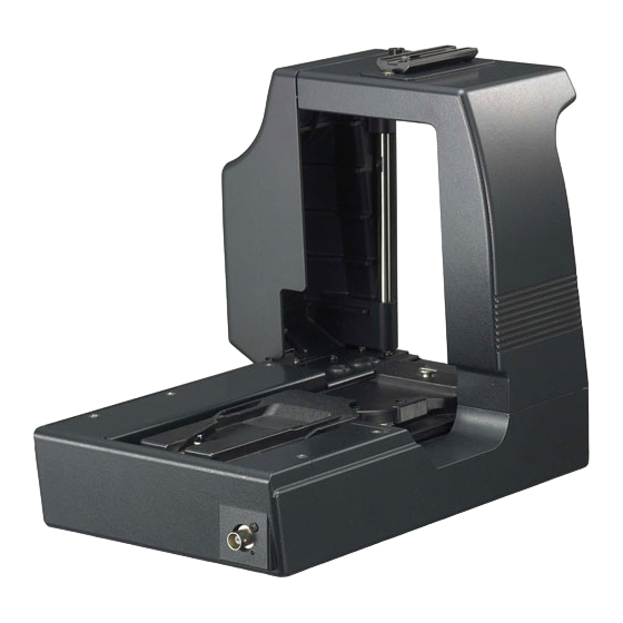
STUDIO ADAPTER
STUDIOADAPTER
APTATEUR DE STUDIO
ADAPTADOR DE ESTUDIO
ADATTATORE STUDIO
KA-HD250
For Customer Use:
Enter below the Serial No. which is located on the body.
Retain this information for future reference.
Model No.
KA-HD250
Serial No.
INSTRUCTIONS
BEDIENUNGSANLEITUNG
INSTRUCTIONS
INSTRUCCIONES
ISTRUZIONI
LST0445-001B
Kapitel
Inhaltsverzeichnis

Verwandte Anleitungen für JVC KA-HD250


Inhaltszusammenfassung für JVC KA-HD250
- Seite 17 STUDIOADAPTER KA-HD250 BEDIENUNGSANLEITUNG...
-
Seite 18: Einführung
(EMV) (z. B. speziell gebautes Sende- oder Aufnahmestudio) und Wenn Sie dieses Produkt entsorgen möchten, besuchen Sie im Freien ländlicher Umgebungen. bitte unsere Webseite www.jvc-europe.com, um Informatio- Um eine optimale Leistung sowie eine elektromagnetische Kompati- nen zur Rücknahme des Produkts zu erhalten. -
Seite 19: Besondere Merkmale
Wir bedanken uns für den Kauf dieses Produkts. INHALTSVERZEICHNIS (Diese Bedienungsanleitung gilt für folgendes Modell: KA- HD250U.) Bevor Sie dieses Gerät verwenden, lesen Sie sorgfältig die Bedienungsanleitung durch, um eine optimale Leistung sicherzustellen. EINFÜHRUNG Besondere Merkmale Besondere Merkmale ......19 Vorsichtsmaßnahmen für die Bedienung . -
Seite 20: Vorsichtsmaßnahmen Für Die Bedienung
: Seiten oder Punkte, die als Querverweis die- nen. In diesem Handbuch verwendete Schreibweise • JVC besitzt das Urheberrecht für dieses Handbuch. Eine unbefugte Vervielfältigung oder Veröffentlichung dieses Handbuchs, auch auszugsweise, ist strengstens untersagt. • Alle in diesem Dokument aufgeführten Produktnamen sind Marken oder eingetragene Marken der jeweiligen Unternehmen. -
Seite 21: Bedienungselemente, Anzeigen Und Anschlüsse
Gerät wieder in Betrieb zu nehmen. Sollte GY-HD250 angeschlossen. das Gerät immer noch nicht funktionieren, wenden Sie eStudiokabel [STUDIO] (10-polig, rund) sich an Ihren autorisierten JVC-Händler. Dient zum Anschließen an die STUDIO-Buchse des GY- 7[VF OUTPUT] (Y/P /RGB) 3× BNC HD250. -
Seite 22: Rückseite
EINFÜHRUNG k[CALL] Ruftaste/Power-Anzeige Bedienungselemente, Anzeigen Leuchtet grün, wenn der Studioadapter eingeschaltet ist. Leuchtet jedoch gelb auf, wenn die Kamera ausgeschaltet und Anschlüsse (Fortsetzung) ist. Muss gedrückt werden, um ein Rufsignal an den Bediener der Fernsteuereinheit zu senden, wenn das Intercom- Headset nicht verwendet wird. -
Seite 23: Vorbereitungen
(rund, 20-polig) STATUS DT109 (Beyerdynamic) WHT.BAL AUTO AUTO AUDIO CH-1 LEVEL CH-2 POWER HD-CAMCORDER INTERCOM-Anschluss GY-HD250/GY-HD251 STUDIO KIT KA-HD250 Gleichstromkabel Netzadapter IA-60a, VL-2PLUS (IDX) Gleichstromeingang DC INPUT PROMPTER OUTPUT Anschlussbuchse RM-Anschluss Fernsteuerkabel Stativ REMOTE CONTROL UNIT RM-P210 MENU/SHUTTER GAIN WHITE... -
Seite 24: Installation
VORBEREITUNGEN Halten Sie den Sicherheitshebel gedrückt, und ziehen Installation Sie den Verriegelungshebel nach vorn, bis die vordere Befestigungsklemme einrastet. Stift Anbringen an einem Stativ Verriegelungshebel Zum Anbringen an einem Stativ verwenden Sie die Befesti- gungslöcher an der Unterseite. Sicherheitshebel Es sind mehrere Befestigungslöcher vorhanden. Für die Vordere Befesti- Montage auf einem Stativ verwenden Sie die Löcher, die die... -
Seite 25: Anschließen Von Kabeln
Anschließen von Kabeln Anschließen des Suchers (VF-P400) Schließen Sie die Kabel für dieses Gerät an der Kamera an. Lösen Sie den Sicherungshebel. GENLOCK/AUX IN Drehen Sie den Sucher-Sicherungshebel im entgegenge- HD/SD setzten Uhrzeigersinn, und lösen Sie den Sicherungshebel. TC IN Bringen Sie den Sucher an. -
Seite 26: Ausgegebene Signale Bei Anschluss Des Suchers
VORBEREITUNGEN Anschließen an die Fern- Ausgegebene Signale bei Anschluss des Suchers steuereinheit RM-P210 Die Signale und Anzeigen von VF OUTPUT können Sie der untenstehenden Tabelle entnehmen. Anschlussverbindung VF-P400 ↓ Schalten Sie zuerst die Stromversorgung des RM-P210 aus, schluss- (Round (BNC×3) (BNC×3) (BNC×3) (BNC×3) -
Seite 27: Einstellung Des Menübildschirms
Anschließen eines Monitors Ablauf Prompter-Videosignale (Eingangssignale des RM-P210- Anschlusses [AUX VIDEO INPUT]) vom RM-P210 kön- nen verifiziert werden, indem der an der Vorderseite die- Schalten Sie den RM-P210 an. Geräts befindliche Anschluss [PROMPTER Drehen Sie den [POWER]-Schalter der Kamera-Fern- OUTPUT] über ein BNC-Kabel an einen Monitor ange- steuereinheit auf [ON]. -
Seite 28: Hinweise Zum Bedienen Des Rm-P210
VORBEREITUNGEN Funktion Aktion Hinweise zum Bedienen GAMMA × × des RM-P210 DNR LEVEL × Einige Aktionen sind nicht kompatibel, wenn der GY-HD250 MIDDLE × über Menübefehle des RM-P210 bedient wird. HIGH × (G: Aktion verfügbar ×: Keine Aktion) AUTO × Funktion Aktion DTL FRQ... -
Seite 29: Sonstiges
SONSTIGES Technische Daten Vielpoliger RM-Stecker: Composite-Videosignalausgang (Es können entweder Y/P -, RGB- oder Y/C-Trenn-Aus- gabesignale gewählt werden) PROMPTER-Ausgang: PROMPTER-Videosignalausgang (Composite-Signal) Temperaturbereich für den Betrieb: • -5 °C bis 40 °C (Luftfeuchtigkeit unter 80%) Temperaturbereich für die Aufbewahrung: • -20 °C bis 60 °C Spannung der Stromversorgung: 12 V Gleichstrom Leistungsaufnahme:... - Seite 31 ADAPTATEUR DE STUDIO KA-HD250 INSTRUCTIONS...
- Seite 45 ADAPTADOR DE ESTUDIO KA-HD250 INSTRUCCIONES...
- Seite 59 ADATTATORE STUDIO KA-HD250 ISTRUZIONI...