
Verwandte Anleitungen für heatapp! BASE

Inhaltszusammenfassung für heatapp! BASE
- Seite 1 0450000516-1448-11 Installationsanleitung heatapp! System Installation instructions for heatapp! system...
-
Seite 2: Inhaltsverzeichnis
Aufstellen ..............15 3.3.2 Anschließen ..............15 3.3.3 Inbetriebnahme / Ersteinrichtung ........17 heatapp!-Funkkomponenten ............19 3.4.1 heatapp! floor und heatapp! sense für Fußbodenheizung ............20 3.4.2 heatapp! drive für Heizkörper ........23 3.4.3 Verbindungstest ............25 3.4.4 heatapp! repeater ............26 heatapp! App ................ -
Seite 3: Sicherheitshinweise
Sicherheitshinweise Allgemeines • Die Geräte sind nicht für Kinder geeignet und dürfen nicht als Spielzeug verwendet werden. • Verpackungsmaterialien kindersicher lagern oder entsorgen. • Die Geräte nicht zerlegen, sie enthalten keine vom Benutzer zu wartenden Teile. Wenn Defekte auftreten, bitte Ihren Installateur informieren. -
Seite 4: Beschreibung
Bedarfsanforderung gemäß EN 1523 möglich. Das heatapp! System beinhaltet folgende Komponenten: heatapp! base Die heatapp! base ist die zentrale Steuer- und Regeleinheit des Systems. Die heatapp! base kann mit dem Wärmeerzeuger einer bestehenden Anlage kommunizieren und den Wärmebedarf an den Wärmeerzeuger übermitteln. - Seite 5 Heizkörpers. Der heatapp! drive kommuniziert per Funk mit dem heatapp! gateway. heatapp! floor Der heatapp! floor ist ein Regelsystem für das heatapp! System zur Einzelraumregelung von Fußbodenheizungen und - heizschlangen in Heizungsanlagen. Es können acht Kanäle mit jeweils bis zu drei thermoelektrischen Stellantrieben geregelt werden.
-
Seite 6: Lieferumfang
• heatapp! sense (Anzahl abhängig von der Bestellung) • • Netzteil für heatapp! gateway (1x) • Netzwerkkabel für heatapp! base und heatapp! gateway (2x) • Netzkabel mit Schukostecker für heatapp! base (1x) • Kurzanleitungen für die Produkte Zubehör Folgende Komponenten sind als Zubehör lieferbar: heatapp! repeater •... -
Seite 7: Montage Und Inbetriebnahme
Montage und Inbetriebnahme Bitte halten Sie die vorgegebene Reihenfolge bei der Montage und Inbetriebnahme der heatapp! base und des heatapp! gateway ein. 1. Zuerst die heatapp! base vollständig einrichten, 2. dann das heatapp! gateway einrichten. Die vollständige Bedienungsanleitung des heatapp! Systems ist unter www.heatapp.de verfügbar. -
Seite 8: Heatapp! Base
3.2.1 Öffnen des Gehäuses Abb. 2: Gehäuse öffnen A Schieben Sie die Klemmenabdeckung bis zum Anschlag ca. 1 cm nach unten. B Drücken Sie die Verriegelung der Klemmenabdeckung mit einem Schraubendreher vorsichtig auseinander. Um eine Beschädigung der Elektronik zu vermeiden, führen Sie den Schraubendreher dabei nicht zu tief ein. -
Seite 9: Montage
3.2.2 Montage Abb. 3: Wandmontage Finden Sie einen geeigneten Montageort für die heatapp! base an einer Wand der die nachfolgenden Anforderungen erfüllt: Am Montageort der heatapp! base muss ein 230 V Anschluss • zur Verfügung stehen. • Der Montageort muss sich in der Nähe des Wärmeerzeugers befinden, wenn die heatapp! base eine Verbindung zum Wärmeerzeuger nutzen soll (z.B. -
Seite 10: Anschließen
3.2.3 Anschließen Abb. 4: heatapp! base 10 - DE... - Seite 11 Anlage spannungsfrei schalten. • Gegen Wiedereinschalten sichern. • Spannungsfreiheit kontrollieren. A Verbinden Sie die heatapp! base mit dem Heimnetzwerk des Kunden. • Per Netzwerkkabel (3) mit einem freien Ethernet Port am Internetrouter oder Switch des Kunden. Die Länge der Gesamtkabelstrecke von der heatapp! base bis zum nächsten Switch oder Router darf maximal 100m betragen.
- Seite 12 Wählen Sie später im Einrichtungsassistenten im Bereich „Wärmeerzeuger“ die Option „Wärmeerzeuger Automat (OT/Bus)“. • Stellsignal 0-10 V: Die heatapp! base wandelt die Vorgabe der Vorlauftemperatur oder der Leistung für den Wärmeerzeuger in ein Ausgangssignal 0-10 V um. Die Parametereinstellung hierfür erfolgt im Profi-Modus des heatapp! base Menüs.
-
Seite 13: Inbetriebnahme / Ersteinrichtung
3.2.4 Inbetriebnahme / Ersteinrichtung Abb. 5: Ersteinrichtung heatapp! base heatapp! USB-LAN Adapter Die Ersteinrichtung der heatapp! base erfolgt menügeführt über den Einrichtungsassistenten am Browser des angeschlossenen PC / Laptops. In den Netzwerkeinstellungen des PCs / Laptops muss DHCP (automatische Adressvergabe) aktiviert sein und es darf kein Proxyserver aktiviert sein. - Seite 14 1. Schalten Sie die Spannungsversorgung für die heatapp! base ein. 2. Verbinden Sie den heatapp! USB-LAN Adapter aus dem Installations-Kit mit der heatapp! base und dem PC / Laptop: A Stecken Sie den heatapp! USB-LAN-Adapter in einen freien USB-Port auf der Oberseite der heatapp! base.
-
Seite 15: Heatapp! Gateway
3.3.1 Aufstellen Das heatapp! gateway ist zur Aufstellung als Tischgerät vorgesehen. Finden Sie einen geeigneten Aufstellort für das heatapp! gateway der die nachfolgenden Anforderungen erfüllt: • Am Aufstellort des heatapp! gateway muss eine 230 V Schutzkontaktsteckdose zur Verfügung stehen. - Seite 16 A Verbinden Sie das heatapp! gateway mit dem LAN-Netzwerk des Kunden: • Per Netzwerkkabel mit einem freien Ethernet Port am Internetrouter oder Switch des Kunden. Die Länge der Gesamtkabelstrecke vom heatapp! gateway bis zum nächsten Switch oder Router darf maximal 100 m betragen.
-
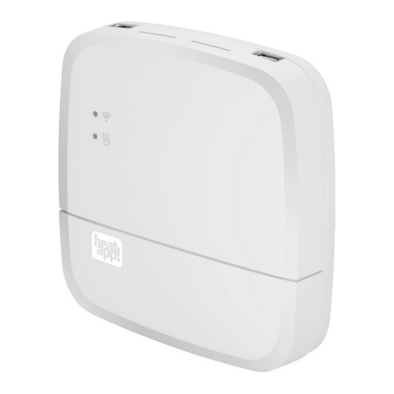
Seite 17: Inbetriebnahme / Ersteinrichtung
3.3.3 Inbetriebnahme / Ersteinrichtung Abb. 7: Ersteinrichtung heatapp! gateway heatapp! USB-LAN Adapter Die Ersteinrichtung des heatapp! gateway erfolgt menügeführt über den Einrichtungsassistenten am Browser des angeschlossenen PC / Laptops. In den Netzwerkeinstellungen des PCs / Laptops muss DHCP (automatische Adressvergabe) aktiviert sein, und es darf kein Proxyserver aktiviert sein. - Seite 18 Installations-Kit mit dem heatapp! gateway und dem PC / Laptop: A Stecken Sie den heatapp! USB-LAN-Adapter in einen freien USB-Port auf der Oberseite des heatapp! gateway. B Starten Sie den PC / Laptop. Verbinden Sie den heatapp! USB-LAN-Adapter mit dem Netzwerkanschluss des PCs / Laptops.
-
Seite 19: Heatapp!-Funkkomponenten
Falls noch nicht geschehen, verbinden Sie den heatapp! USB-LAN- Adapter aus dem Installations-Kit mit dem heatapp! gateway und dem PC / Laptop (siehe Kapitel 3.3.3 "Inbetriebnahme / Ersteinrichtung"). Das Menü des heatapp! gateway wird kurz darauf automatisch im Browserfenster Ihres PCs angezeigt. -
Seite 20: Heatapp! Floor Und Heatapp! Sense Für Fußbodenheizung
3.4.1 heatapp! floor und heatapp! sense für Fußbodenheizung Abb. 8: heatapp! floor / heatapp! sense anmelden 20 - DE... - Seite 21 Funkraumfühler einen Raum zuzuweisen und einen Namen (z. B. Wand links) zu vergeben. Nur bei heatapp! floor: Erkennt das heatapp! gateway den heatapp! floor, so werden Sie aufgefordert einen Namen (z.B. Erdgeschoss) zu vergeben. 4. Prüfen Sie im Menü des heatapp! gateway unter "Funkkomponenten", ob der heatapp! floor oder das...
-
Seite 22: Funktionen Der Lerntaste
3.4.1.2 Funktionen der Lerntaste Abb. 9: Funktionen der Lerntaste 22 - DE... -
Seite 23: Heatapp! Drive Für Heizkörper
3.4.2 heatapp! drive für Heizkörper Abb. 10: heatapp! drive anmelden DE - 23... - Seite 24 3.4.2.1 Anmelden der heatapp! drive-Stellantriebe Beachten Sie die Installationsanleitung für das heatapp! drive! 1. Packen Sie einen heatapp! drive aus und legen Sie die AA- Batterien in das Batteriefach ein (Abb. 10, A). Achten Sie dabei auf die richtige Polarität! 2.
-
Seite 25: Verbindungstest
Falls dies nicht ausreicht, ergänzen Sie einen heatapp! repeater • zur Verbesserung der Funkabdeckung. Folgen Sie den Anweisungen zur Montage und Anmeldung eines heatapp! repeater im Kapitel 3.4.4 "heatapp! repeater". Der heatapp! repeater ist nicht im Standard-Lieferumfang enthalten, sondern muss als Zubehör bestellt werden. DE - 25... -
Seite 26: Heatapp! Repeater
"Funkkomponenten" den Menüpunkt „An- / Abmelden“ und dann „Anmelden“. Sie werden aufgefordert, die Lerntaste am heatapp! repeater zu drücken. 3. Drücken Sie nun den Lerntaste am heatapp! repeater. Erkennt das heatapp! gateway den heatapp! repeater, werden Sie aufgefordert, einen Namen zu vergeben (z.B. „Repeater Obergeschoss“). -
Seite 27: Heatapp! App
Hinweise und Rechteanfragen während der Installation bestätigen. 2. Stellen Sie nun sicher, dass das Endgerät mit dem Heimnetzwerk des Kunden verbunden ist, in dem sich auch die heatapp! base befindet. Gehen Sie dazu bei Apple iOS-Geräten und bei Android- Geräten in die WLAN-Einstellungen und kontrollieren Sie, ob WLAN eingeschaltet und mit dem richtigen Netzwerk verbunden ist. - Seite 28 Sie das Tutorial mit dem (?)-Symbol auf, um sich die Bedienung erläutern zu lassen. 9. Zeigen Sie dem Kunden, wie er angelegte Benutzer zu heatapp! connect für die Fernbedienung des heatapp! Systems einladen kann. Tun Sie dies beispielhaft mit Ihrem Fachmann-Benutzer, wenn der Kunde zustimmt.
-
Seite 29: Benutzerrollen
"Schaltzeiten", "Design" und "Live View". Verwalter: • Der Verwalter kann alle Räume verwalten. Der Verwalter hat Zugriff auf alle Einstellungen, auf das Menü "heatapp! base" und das Menü "heatapp! gateway". Der Verwalter hat eingeschränkte Rechte im Bereich "Profi". • Fachmann: Der Fachmann hat dieselben Rechte wie der Verwalter. -
Seite 30: Nachrüsten Von Funkkomponenten
Nutzen Sie zur späteren Nachrüstung weiterer Funkkomponenten möglichst die heatapp! App auf einem Tablet, das mit dem Heimnetzwerk des Kunden verbunden ist. 1. Melden Sie sich an der heatapp! App als Benutzer mit der Benutzerrolle "Fachmann" oder "Verwalter" an. 2. Wählen Sie den Bereich "Einstellungen". -
Seite 31: Technische Daten
Technische Daten heatapp! base Wandbefestigung Montage Linux Betriebssystem Anschlüsse • 2 x USB 2.0 • extern • RJ45 Ethernet • Netzspannung L/N/PE • intern (Schraub- • Wärmeerzeuger Relais klemmen) • Wärmeerzeuger Bus (OpenTherm) • 0 ... 10 V Ausgang 230 V ± 10 %, 50 Hz, 5 VA... -
Seite 32: Heatapp! Gateway
Tischgerät Montage Funksystem • Z-Wave Statischer dedizierter Controller • WLAN Integriertes WLAN-Modul 802.11b/g/n • USB 2.0 Anschlüsse • RJ45 Ethernet Euro-Steckernetzteil 5 V DC, 1 A Spannungsversorgung Umgebungsbedingungen • Lagertemperatur -25 ... +60 °C • Betriebstemperatur -10 ... +50 °C... -
Seite 33: Anhang
Anhang LEDs heatapp! base Netzwerk Regelung Startsequenz Schritt 1 - leuchtet Spannungsversorgung eingeschaltet weiß Startsequenz Schritt 2 - leuchtet Starten des Betriebssystems gelb Startsequenz Schritt 3 - blinkt grün Netzwerk und Internetverbindung herstellen Netzwerk- und Regelung betriebsbereit leuchtet Internetverbindung grün... -
Seite 34: Leds Heatapp! Gateway
Starten des Betriebssystems gelb Startsequenz Schritt 3 - blinkt grün Netzwerk und Internetverbindung herstellen Netzwerk- und Internetverbindung hergestellt leuchtet grün Netzwerkverbindung hergestellt, keine heatapp! base leuchtet gefunden. Netzwerkkonfiguration prüfen! gelb Keine Netzwerkverbindung möglich. leuchtet LAN: Kein Netzwerkkabel angeschlossen? WLAN: Falsche Zugangsdaten ? Systemfehler - Update über Internet / USB... -
Seite 35: Konformitätserklärung
Konformitätserklärung DE - 35... - Seite 36 0450000516-1448-11 Installation instructions for heatapp! system...
- Seite 37 3.3.2 Connecting ..............15 3.3.3 Initial operation / initial configuration ......17 heatapp! radio modules ............. 19 3.4.1 heatapp! floor and heatapp! sense for underfloor heating ................. 20 3.4.2 heatapp! drive for radiators..........23 3.4.3 Connection test ............. 25 3.4.4 heatapp! repeater ............
-
Seite 38: Safety Instructions
Safety instructions General information • The devices are not suitable for children and must not be used as toys. • Store packaging material safely away from children or dispose of it. • Do not dismantle the devices; they do not contain any user- serviceable parts. -
Seite 39: Description
network. - Seite 40 All radio modules used to control the radiators (heatapp! drive), underfloor heating systems (heatapp! floor) and room temperature measurement (heatapp! sense) are connected to heatapp! base via the heatapp! gateway.
-
Seite 41: Scope Of Delivery
(number depends on the order) • Mains adapter for heatapp! gateway (1x) • Network cable for heatapp! base and heatapp! gateway (2x) Mains cable with CEE 7/7 plug for heatapp! base (1x) • • Quick start guides for the products Accessories The following components are available as accessories: •... -
Seite 42: Installation And Initial Operation
The full operating instructions for the heatapp! system are available at www.heatapp.de. Conditions and requirements For initial operation of a heatapp! system a standard laptop and the heatapp! installation kit comprising the heatapp! USB-LAN Adapter and a network cable are required. -
Seite 43: Heatapp! Base
3.2.1 Opening the housing Fig. 2: Opening the housing A Push the terminal cover up to the stop approximately 1 cm downwards. B Press the latch of the terminal cover carefully apart using a screwdriver. To prevent damage to the electronics, do no push the screwdriver in too far when doing so. - Seite 44 Install the heatapp! base with the supplied installation material in the selected installation location (Fig. 3, A - C). The heatapp! Wi-Fi stick is not included in the standard scope of delivery; it must be ordered as an accessory. 9 - EN...
- Seite 45 3.2.3 Connecting Fig. 4: heatapp! base 10 - EN...
- Seite 46 B Connect the heat generator (Fig. 4, item. 4, optional) according to the terminal configuration on the heatapp! base. The heatapp! Wi-Fi stick is not included in the standard scope of delivery; it must be ordered as an accessory. 11 - EN...
- Seite 47 OT interface open to external connections. E.g. an OT room station can be replaced by the heatapp! base. Connect the OpenTherm link cable to the terminals OT/BUS (in doing so, ensure correct polarity A / B!).
-
Seite 48: Initial Operation / Initial Configuration
Initial operation / initial configuration Fig. 5: Initial set-up heatapp! base heatapp! USB-LAN adapter The initial set-up of the heatapp! base is performed based on a menu control system via the browser-based set-up wizard of the connected PC / laptop. - Seite 49 2. Connect the heatapp! USB-LAN adapter from the installation kit to the heatapp! base and the PC / laptop: A Plug the heatapp! USB-LAN adapter into a free USB port on the top side of the heatapp! base. B Start the PC / laptop. Connect the heatapp! USB-LAN adapter to the network port of the PC / laptop.
- Seite 50 3.3.1 Setting up The heatapp! gateway is designed to be set up as a table-top unit. Find a suitable installation location for the heatapp! gateway that fulfils the following requirements: • A 230 V outlet must be available at the installation location of the heatapp! gateway.
-
Seite 51: Heatapp! Gateway
• Via a network cable plugged into a free Ethernet port on the customer's internet router or switch. The maximum total cable length from the heatapp! gateway to the next switch or router must not exceed 100 m. • Alternatively via Wi-Fi connection using the Wi-Fi module integrated in the heatapp! gateway. - Seite 52 Initial operation / initial configuration Fig. 7: Initial set-up heatapp! gateway heatapp! USB-LAN adapter The initial set-up of the heatapp! gateway is performed based on a menu control system via the set-up wizard via the browser of the connected PC / laptop.
- Seite 53 3. Follow the instructions in the set-up wizard. After set-up the heatapp! gateway is successfully connected to the customer network, the heatapp! base and the Internet if the LED on the side heatapp! gateway remains a steady GREEN. Please refer to section 5.2 "LEDs heatapp! gateway"...
-
Seite 54: Heatapp! Radio Modules
1. Log in using the password you created. 2. Register all the radio modules with the heatapp! gateway according to the following descriptions. 3. After setting up all the radio modules, you can remove the heatapp! USB-LAN adapter. NOTE If present, first register any heatapp! floor because they have a repeater function and help to increase wireless coverage. -
Seite 55: Heatapp! Floor And Heatapp! Sense For Underfloor
3.4.1 heatapp! floor and heatapp! sense for underfloor heating Fig. 8: Registering heatapp! floor / heatapp! sense 20 - EN... - Seite 56 Registering with the heatapp! gateway A, B: 1. In the menu of the heatapp! gateway select the menu item "Register / deregister" under "Radio modules" and then "Register". You are requested to press the learn key (Fig. 8, item 2).
- Seite 57 3.4.1.2 Functions of the learn key Fig. 9: Functions of the learn key 22 - EN...
-
Seite 58: Heatapp! Drive For Radiators
3.4.2 heatapp! drive for radiators Fig. 10: registering heatapp! drive 23 - EN... - Seite 59 3.4.2.1 Registering the heatapp! drive actuators Observe the installation instructions for the heatapp! drive! 1. Unpack a heatapp! drive and insert the AA batteries in the battery compartment (Fig. 10, A). Ensure you connect the positive and negative terminals correctly! 2.
-
Seite 60: Connection Test
Follow the instructions for installation and registering a heatapp! repeater in section 3.4.4 "heatapp! repeater". The heatapp! repeater is not included in the standard scope of delivery; it must be ordered as an accessory. 25 - EN... -
Seite 61: Heatapp! Repeater
If this does not work, add a further heatapp! repeater to improve • wireless coverage. The heatapp! repeater is not included in the standard scope of delivery; it must be ordered as an accessory. 26 - EN... - Seite 62 App You can help the customer to start using the heatapp! system by helping them to install the app on their own mobile device and guiding them through the first few steps in using the app. 1. Show the customer how to download the app from the store and install it on their mobile device (tablet or smartphone).
- Seite 63 "Settings / user" and click on the symbol (+) at the bottom right. Call the tutorial using the (?) symbol in order to explain operation. 9. Show the user how they can invite created users to join heatapp! connect for remote control of the heatapp! system. For example do this to set up an expert user - provided the customer agrees.
-
Seite 64: User Roles
"Switching times", "Design" and "Live View". Owner: • The Owner can manage all rooms. The Owner has access to all settings in the menu "heatapp! base" and the menu "heatapp! gateway". The Owner has limited rights in the "Expert mode" field. •... - Seite 65 Where possible use the heatapp! App on a tablet connected to the customer's home network for subsequent retrofitting of additional radio modules. 1. Log in to the heatapp! App as a user with "Expert" or "Owner" rights. 2. Select the field "Settings".
-
Seite 66: Technical Data
Technical data heatapp! base Wall mounting Installation Linux Operating system Connections • 2 x USB 2.0 • External • RJ45 Ethernet • Mains voltage L/N/PE • Internal (screw • Heat generator relay terminal) • Heat generator bus (OpenTherm) • 0 ... 10 V output 230 V ±... - Seite 67 Table device Installation Wireless system • Z-wave Static dedicated controller • Wi-Fi Integrated Wi-Fi module 802.11b/g/n • USB 2.0 Connections • RJ45 Ethernet Euro plug power supply unit 5 V DC, Power supply Ambient conditions • Storage temperature -25 ...
- Seite 68 Appendix LEDs heatapp! base Network Control Start sequence step 1 - Steady power supply switched on white Start sequence step 2 - Steady starting of the operating system yellow Start sequence step 3 - Flashes create network and Internet connection...
- Seite 69 Start sequence step 3 - Flashes create network and Internet connection green Network and Internet connection created Steady green Network connection made, no heatapp! base found. Steady Check network configuration! yellow No network connection possible. Steady red LAN: No network cable connected? Wi-Fi: Incorrect access data? System fault - update via Internet / USB necessary.
-
Seite 70: Conformity Declaration
Conformity declaration 35 - EN... - Seite 72 © Copyright by Elektronikbau und Vertriebs-GmbH Heisterner Weg 8-12 D-57299 Burbach www.heatapp.de info@heatapp.de The device must be disposed of as electronic waste.