Inhaltsverzeichnis
Werbung
Verfügbare Sprachen
Verfügbare Sprachen
Quicklinks
Camille Bauer AG
Aargauerstrasse 7
CH-5610 Wohlen/Switzerland
Telefon +41 56 618 21 11
Telefax +41 56 618 35 35
info@camillebauer.com
www.camillebauer.com
Betriebsanleitung
Grenzwertmelder SIRAX C 402
Mode d'emploi
Détecteur de seuil SIRAX C 402
Operating Instructions
Alarm unit SIRAX C 402
C 402-6 Bd-f-e
129 313-04
03.10
1
Werbung
Kapitel
Inhaltsverzeichnis

Verwandte Anleitungen für Camille Bauer SIRAX C 402


Inhaltszusammenfassung für Camille Bauer SIRAX C 402
- Seite 1 Betriebsanleitung Grenzwertmelder SIRAX C 402 Mode d’emploi Détecteur de seuil SIRAX C 402 Operating Instructions Alarm unit SIRAX C 402 C 402-6 Bd-f-e 129 313-04 03.10 Camille Bauer AG Aargauerstrasse 7 CH-5610 Wohlen/Switzerland Telefon +41 56 618 21 11 Telefax +41 56 618 35 35 info@camillebauer.com...
- Seite 2 Betriebsanleitung Grenzwertmelder SIRAX C 402 ............Seite 3 Mode d’emploi Détecteur de seuil SIRAX C 402 ............Page 10 Operating Instructions Alarm unit SIRAX C 402 ..............Page 17 Das Gerät darf nur zum Konfi gurieren, wie in Abschnitt «6. Konfi - guration» beschrieben, geöffnet werden.
-
Seite 3: Inhaltsverzeichnis
● Grenzwertmelder auf Geräteträger aufsteckbar (mechanische 0…10 V, 2…10 V, ± 10 V Verriegelung durch Schnellverschlüsse), Elektrische Anschlüsse Grenzwerte getrennt vom SIRAX C 402 auf Geräteträger geführt / Lösen und 0…0,06 bis 0…40, Ex max. 30 V Wiederanklemmen der Verdrahtung bei Gerätetausch entfällt auch live-zero, ●... -
Seite 4: Einbauangaben
Brennbarkeitsklasse V-0 nach UL 94, selbstverlöschend, nicht tropfend, Grenzwerteinstellung: Mit 12-Gang-Potentiometer halogenfrei 2 für GW1 und GW2 Bezeichnung: SIRAX C 402 Eingestellter Grenzwert an Prüf- buchsen mit separatem Voltmeter Gebrauchslage: Beliebig > 10 MΩ messbar, Elektrische Anschlüsse: 96-poliger Stecker nach DIN 41 612, 0 …... -
Seite 5: Umgebungsbedingungen
Prüfspannung: 50 Hz, 1 Min. nach Bestell-Code 402 – DIN EN 61 010-1 5. Grenzwert 1, Typ, Hysterese 2300 V, Eingang gegen Ausgänge Unterer Grenzwert, Hysterese 1% sowie Ausgänge gegeneinander Unterer Grenzwert, Hysterese [%] 3700 V, Hilfsenergie gegen alles Hysterese [%] > 1,0 bis 10 Umgebungsbedingungen Oberer Grenzwert, Hysterese 1% Inbetriebnahme:... -
Seite 6: Explosionsschutz
Steckbrücken Grenzwert Grenzwert-Typ Stellung ST 2 ST 6 6. Konfi guration Zur Konfi guration des SIRAX C 402 muss das Gerät geöffnet oberer werden. unterer Eingangs-Standardbereiche Je nach Lage «B1, B2 oder B3» der Steckbrücke J1 lässt sich der Messeingang einstellen. -
Seite 7: Wirkungsrichtung Der Leuchtdioden
Gutbereich Leucht- dioden brennen Störfall Bild 3. Anordnung der Steckbrücken, Potentiometer, Prüfbuchsen GW 1 und LED’s. Gutbereich 7. Elektrische Anschlüsse SIRAX C 402 SIRAX C 402 Frontseite Rückseite Schnellverschluss – Potentiometer für Grenzwert GW 2 Camille Bauer AG CH-5610 Wohlen Switzerland Prüfbuchsen zu GW 2... -
Seite 8: Zubehör Und Einzelteile
24…60 V DC/AC 85…230 V DC/AC Zum Schliessen des Gerätes Führungsstege in Gehäuse- schale einführen und beide Gehäuseteile leicht zusammen- Bild 4. Codierung des Steck-Moduls SIRAX C 402 in Standard- (Nicht Ex)-Ausführung. drücken bis die Verzapfungen ineinander einrasten. 11. Montage Legende zu den Bildern 4 und 5: Der Grenzwertmelder SIRAX C 402 wird auf einen Geräte-... -
Seite 9: Steck-Modul Auf Geräteträger Aufstecken
14. Demontage-Hinweis 1. Schnellverschluss um 90° drehen. 2. Steck-Modul herausziehen. 11.1 Steck-Modul auf Geräteträger aufstecken Vor dem Einstecken des SIRAX C 402 in den Geräteträger unbedingt sicher stellen, … … dass die Elektrischen Anschlüsse des Geräteträgers mit dem Anschlussplan des Steck-Moduls übereinstimmen... -
Seite 10: Application
0…10 V, 2…10 V, ± 10 V mécanique par fi xation rapide), raccordements électriques sur le Valeurs limites support d’appareils, séparés du SIRAX C 402 / Le câblage reste 0…0,06 à 0…40, Ex max. 30 V en place lors d’un échange d’appareil ainsi que live zéro,... -
Seite 11: Normes Et Prescriptions
Avec potentiomètre à 12 tours UL 94, à auto-extinction, ne gouttant 1 et 2 pour GW1 et pas, exempt d’halogène Désignation: SIRAX C 402 Le réglage des seuils est contrôlable sur les prises de test avec un volt- Position d’utilisation: Quelconque mètre séparé R >... -
Seite 12: Codage Des Variantes
Tension d’essai: 50 Hz, 1 min. selon Code de commande 402 – DIN EN 61 010-1 4. Seuils / Sorties contact 2300 V, entrée contre sorties et sorties 2 seuils, entre eux 1 contact inverseur par seuil 3700 V, alimentation auxiliaire contre 5. -
Seite 13: Sécurité Intrinsèque
Type Position ST 2 ST 6 6. Confi guration maximum Pour la confi guration du SIRAX C 402, il faut ouvrir l’appa- reil. minimum Etendues d’entrée standard En fonction du positionnement «B1, B2 ou B3» de la barrette maximum J1, il est possible de modifi er l’entrée de mesure. -
Seite 14: Raccordements Électriques
Etat alarme GW 1 Fig. 3. Disposition des barrettes, potentiomètres, prises de test et Etat DEL’s. normal 7. Raccordements électriques SIRAX C 402 SIRAX C 402 Face avant Face arrière Fixation rapide – Potentiomètre pour seuil GW 2 Camille Bauer AG... -
Seite 15: Accessoires Et Pièces De Rechange
24…60 V CC/CA 85…230 V CC/CA que les cliquets soient en place. Fig. 4. Codage du module embrochable SIRAX C 402 en exécution standard (non-Ex). 11. Montage Légende pour les Figs. 4 et 5: Le détecteur de seuil SIRAX C 402 est embroché... -
Seite 16: Mise En Service
2. Retirer le module embrochable. 11.1 Monter le module embrochable dans un support d’appareils Avant d’embrocher le SIRAX C 402 dans le support d’appareils, vérifi er sans faute, … … la concordance des raccordements élec- triques du support et du plan de bornes du module embrochable …... -
Seite 17: Features/Benefi Ts
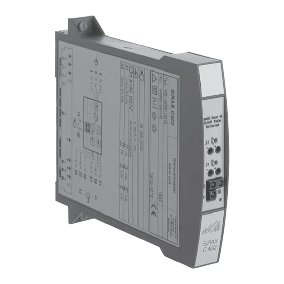
14. Releasing the alarm unit ..........23 15. Dimensional drawing ..........23 16. Declaration of conformity .......... 24 Fig. 1. Plug-in module SIRAX C 402-6 for plugging onto 1. Application backplane BP 902. The alarm unit SIRAX C402 (Figure 1) is normally applied to monitor the limits of both current and voltage measure- ments. - Seite 18 Flammability Class V-0 acc. to UL 94, self-extinguishing, non-dripping, Fig. 2. Switching function, according to trip point type. free of halogen Designation: SIRAX C 402 Trip point adjustment: By 12-turn potentiometer 1 and 2 for GW1 and GW2 Position of use: Adjusted trip point measurable on Electrical connections: 96-pin connector acc.
-
Seite 19: Environmental Conditions
Test voltage: 50 Hz, 1 min. acc. to Order Code 402 – DIN EN 61 010-1 5. Trip point 1, type, hysteresis 2300 V, Input versus outputs and Low alarm, hysteresis 1% outputs versus each other Low alarm, hysteresis 3700 V, Power supply versus all circuits Hysteresis [%] >... -
Seite 20: Explosion Protection
5. Explosion protection II (1) G Table 3: Data on explosion protection Order Type of Mounting Measuring input Output Type examination certifi cate Code protection location = 6 V = 63 μA = 20 μH = 20 nF = 253 V AC Outside the 402-63.. -
Seite 21: Electrical Connections
Alarm condition GW 1 Fig. 3. Positions of the plug-in jumpers, potentiometers, test sockets Safe and LED’s. condition 7. Electrical connections SIRAX C 402 SIRAX C 402 Front Rear Fastener – Potentiometer for trip point GW 2 Camille Bauer AG... -
Seite 22: Accessories And Spare Parts
To assemble the casing, insert the guides into the casing shell and press the two halves together using light pressure Fig. 4. Coding of the plug-in module SIRAX C 402 in standard (non- until the pegs snap into place. Ex) version. -
Seite 23: Commissioning
1. Rotate the quick release screws 90°. 2. Withdraw the plug-in module. 11.1 Plugging the module into the backplane Before inserting the SIRAX C 402 into the backplane, ensure that, … … the backplane wiring is in strict accordance with the wiring diagram of the module …... -
Seite 24: Konformitätserklärung
16. Konformitätserklärung / Certifi cat de conformité / Declaration of conformity EG - KONFORMITÄTSERKLÄRUNG EC DECLARATION OF CONFORMITY D o k u m e n t - N r . / C 4 0 2 S _ C E - k o n f . D O C D o c u m e n t .