Inhaltsverzeichnis
Werbung
Verfügbare Sprachen
Verfügbare Sprachen
Quicklinks
Werbung
Kapitel
Inhaltsverzeichnis
Fehlerbehebung

Verwandte Anleitungen für LEYBOLD TURBOVAC 1100 C


Inhaltszusammenfassung für LEYBOLD TURBOVAC 1100 C
- Seite 1 Applikations- LEYBOLD VACUUM Unterstützung Vakuum-Lösungen Service GA 05.128/7 TURBOVAC 1100 C Turbo-Molekularpumpe mit fettgeschmierten Lagern Turbomolecular pump with grease-lubricated bearings Kat.-Nr. / Cat. No. 894 80 894 83 894 84 Gebrauchsanleitung Operating instructions...
-
Seite 2: Inhaltsverzeichnis
Beschreibung 1 Beschreibung Inhalt Seite Die TURBOVAC 1100 C ist eine Turbo-Molekularpumpe Beschreibung............. 2 mit fettgeschmierten Lagern. Sie ist geeignet zum Lieferumfang............3 Abpumpen von Vakuumbehältern auf Druckwerte im Bestell-Daten ............. 3 Hochvakuumbereich. Zum Betrieb der TURBOVAC sind Technische Daten ..........3 ein Frequenzwandler TURBOTRONIK und eine Vorva- kuumpumpe erforderlich. -
Seite 3: Lieferumfang
Gewicht 22 kg Erforderlicher Frequenzwandler 1.2 Bestelldaten TURBOTRONIK NT 20 Kat.-Nr. 857 20 (230 V) ab Fabr.-Nr. Z9601221 TURBOVAC 1100 C Kat.-Nr. Kat.-Nr. 857 21 (120 V) ab Fabr.-Nr. Z9600321 mit Hochvakuum-Flansch DN 250 ISO-K 894 80 Sperrgas-Anschluss DN 10 KF oder DN 16 KF... -
Seite 4: Anschluss
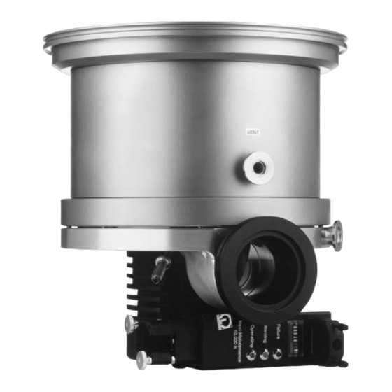
Transport nicht beschädigen. E Anschluss für Wasserkühlung F Anschluss TURBOTRONIK Beim Anschließen oder Ausbauen der TURBOVAC nicht G Sub-D-Stecker für unter der Pumpe stehen. - Meldesignal-Verarbeitung - manuelle Abfrage der Rotorlager-Temperatur Abb. 1 TURBOVAC 1100 C GA 05.128/7 - 05/2002... -
Seite 5: Umweltbedingungen
Dazu sind bei der Befestigung des ISO-K-Hochva- kuum-Flansches 10 Klammerschrauben notwendig. Das Anzieh-Drehmoment der Klammerschrauben ist 35 Nm bei Stahl- und 50 Nm bei Edelstahl-Schrauben. Die Bestell-Nummern der (Klammer-) Schrauben finden Sie im Leybold-Katalog. Klammerschrauben gehören nicht zum Lieferumfang der Pumpe. GA 05.128/7 - 05/2002... -
Seite 6: Vorvakuum-Anschluss
Vorvakuumpumpe und Verbindungsleitung so bar, der am Hochvakuumflansch der TURBOVAC mon- auswählen, dass der Vorvakuumdruck und das Saug- tiert wird. Die TURBOVAC 1100 C bei Anbau über einen vermögen am Vorvakuum-Anschlussflansch bei allen Schwingungsdämpfer zusätzlich an den Füßen oder am Pumpprozessen ausreichend sind. -
Seite 7: Kühlung Anschließen
Anschluss l/min °C Kühlwasser-Temperatur Abb. 5 Kühlwasserbedarf 2.4 Kühlung anschließen 2.5 Sperrgas und Belüftung anschließen Die TURBOVAC benötigt Wasserkühlung. Kühlwasser-Spezifikationen Sperrgas Zulauftemperatur 10 - 30 °C Beim Abpumpen von reaktiven oder staubhaltigen Gasen muss die TURBOVAC mit Sperrgas betrieben Zulaufdruck 3 - 7 bar absolut werden. -
Seite 8: Turbotronik Anschließen
Anschluss Anschluss TURBO- TRONIK Pin-Belegung von X1 grüne LED nicht belegt Schnittstelle gelbe LED Schnittstelle Schnittstelle rote LED Masse Relaiskontakt grüne LED Betriebsstundenzähler Kontakt geschlossen, Relaiskontakt gelbe LED wenn LED aktiv Relaiskontakt rote LED 12 Pt 100 extern Pin 12 und 13 sind 13 Pt 100 Eingang im Stecker gebrückt 14 Pt 100 extern... -
Seite 9: Betrieb
Prozessdrücke prüfen, ggf. ändern. mindestens Evtl. die Temperatur der Failure 1 Stunde Pumpenlager messen. kritischer Die Pumpe so bald wie Betrieb möglich austauschen (> 95 °C) und zum Leybold-Service schicken. Die rote LED ist nicht zurücksetzbar. GA 05.128/7 - 05/2002... -
Seite 10: Abschalten
Betrieb mbar Zeit Abb. 8 Druckanstiegskurve 3.3 Abschalten Vakuumbereich. Somit wird vermieden, dass Partikel, Stäube oder aggressive Gase durch die Lager in den noch nicht belüfteten Motorraum der Pumpe gedrückt Die TURBOVAC an der TURBOTRONIK abschalten. werden. Einzelheiten siehe Gebrauchsanleitung zur TUR- BOTRONIK. -
Seite 11: Pumpe Aus Der Anlage Ausbauen
Öffnen das Ansaug- oder Auspuff-Anschlusses entsprechende 4.1 Service bei LEYBOLD Vorsichtsmaßnahmen treffen. Falls Sie eine Pumpe an LEYBOLD schicken, geben Sie Falls nötig, Handschuhe, Atemschutz oder an, ob die Pumpe frei von gesundheitsgefährdenden Schutzkleidung tragen und unter einem Schadstoffen ist oder ob sie kontaminiert ist. -
Seite 12: Fehlersuche
Messröhre verschmutzt. Messröhre reinigen oder ersetzen. Undichtheit an Apparatur, Leitungen oder Pumpe. Lecksuche. Pumpe verschmutzt. Pumpe reinigen lassen. (nur durch Leybold-Service). Vorvakuumpumpsystem mit zu geringem Enddruck der Vorvakuumpumpe prüfen; Saugvermögen oder zu hohem Enddruck. ggf. größeres Vorvakuumpumpsystem anbauen. Undichtheit an der Stromdurchführung. -
Seite 13: Eg-Herstellererklärung
EG-Herstellererklärung im Sinne der Maschinenrichtlinie 89/392/EWG, Anhang IIb Hiermit erklären wir, die Leybold Vakuum GmbH, dass Angewandte harmonisierte Normen: die Inbetriebnahme der nachfolgend bezeichneten • EN 292 Teil 1 und Teil 2 Nov. 1991 unvollständigen Maschine solange untersagt ist, bis fest- gestellt wurde, dass die Maschine, in die diese unvoll- •... -
Seite 14: Description
“C” in the model TURBOVAC 4.1 Service by Leybold ....23 number are equipped with a purge gas feature, it pro-... -
Seite 15: Standard Equipment
7 l/sec Nominal rotation speed 30,000 r.p.m. Run-up period approx. 9 min. 1.2 Order data Weight 22 kg TURBOVAC 1100 C Part No. Required frequency converter with high-vacuum port DN 250 ISO-K 894 80 TURBOTRONIK NT 20 DN 200 ISO-K 894 83 Ref. -
Seite 16: Connections
G Sub-D socket for Do not stand below the pump while it is being TURBOVAC - Processing status signals connected to or detached from the system. - Manual query of the rotor bearing temperature Fig. 1 TURBOVAC 1100 C GA 05.128/7 - 05/2002... -
Seite 17: Operating Environment
Clamping bolts made of steel must be torqued down to 35 Nm, those made of stainless steel to 50 Nm. You will find the order numbers for the (clamping) bolts in the Leybold Catalog. The clamping bolts are not included as standard equip- ment with the pump. -
Seite 18: Making The Forevacuum Connection
Connections Install outer centering ring Fig. 4 Using ISO-K flanges In most applications the will be flanged direct The pump running noise is below 70 dB(A); no noise- TURBOVAC to the high-vacuum flange for the system. The design of insulating measures are required. the lubricating system makes it possible to mount and run the in any desired attitude. -
Seite 19: Connecting The Cooling
Connections l/min °C Cooling water temperature Fig. 5 Cooling water consumption 2.4 Connecting the cooling 2.5 Connecting the purge gas and the airing device The TURBOVAC must be cooled with water. Cooling water specifications Purging gas Inlet temperature 10 - 30 °C When evacuating reactive gases or gases containing dust, the TURBOVAC will have to be used with purging Inlet pressure... -
Seite 20: Connecting The Turbotronik
Connections Connection TURBO- TRONIK Pin assignment of X1 not connected green LED Interface Interface yellow LED Interface Ground red LED Relay contact green LED Contact Operating hours counter closed Relay contact yellow LED when LED aktive Relay contact red LED 12 Pt 100 external Pins 12 and 13 are 13 Pt 100 Input... -
Seite 21: Operation
Possibly measure the Failure operation pump bearing tempera- for at least ture. Replace the pump 1 hour as soon as possible and (> 95 °C) send it to the Leybold Service. The red LED cannot be reset. GA 05.128/7 - 05/2002... -
Seite 22: Switching Off
Operation mbar Time Fig. 8 Curve showing the pressure rise 3.3 Switching off area. This will prevent particles, dust or aggressive gases from being forced through the bearings into the not yet vented motor chamber of the pump. Switch off the at the . -
Seite 23: Removing The Pump From The System
LEYBOLD If you return a pump to Leybold, be absolutely sure to are not accompanied by a contamination statement. observe the instructions given in Section 4.1. -
Seite 24: Troubleshooting
Clean or replace the measurement gauges. Leak at the system, lines or pump. Locate the leaks. Grime collection at the pump. Have the pump cleaned (only by the Leybold Service Department). Forevacuum pump with insufficient pumping speed Check ultimate pressure of the forevacuum pump or or ultimate pressure which is too high. -
Seite 25: Ec Manufacturer's Declaration
EC Manufacturer’s Declaration in the spirit of Appendix IIb to the 89/392/EEC Machinery Guidelines We, the Leybold Vakuum GmbH, declare herewith that Applicable, harmonized standards: the commissioning of the incomplete machine designa- • EN 292 Part 1 and Part 2... - Seite 26 Erklärung über Kontaminierung von Vakuumgeräten und -komponenten Die Reparatur und/oder die Wartung von Vakuumgeräten und -komponenten wird nur durchgeführt, wenn eine korrekt und vollständig ausgefüllte Erklärung vorliegt. Ist das nicht der Fall, kommt es zu Verzögerungen der Arbeiten. Wenn die Repara- tur/Wartung im Herstellerwerk und nicht am Ort ihres Einsatzes erfolgen soll, wird die Sendung gegebenenfalls zurückgewie- sen.
- Seite 27 Declaration of Contamination of Vacuum Equipment and Components The repair and/or service of vacuum equipment and components will only be carried out if a correctly completed declaration has been submitted. Non-completion will result in delay. The manufacturer could refuse to accept any equipment without a declara- tion.
- Seite 28 LEYBOLD VAKUUM GmbH Bonner Strasse 498 (Bayenthal) D-50968 Köln Tel.: (0221) 347-0 Fax: (0221) 347-1250 http://www.leyboldvac.de e-mail:documentation@leyboldvac.de...