Omnitronic DDC-2000 Bedienungsanleitung
Inhaltsverzeichnis
Verfügbare Sprachen
Verfügbare Sprachen
Quicklinks
Inhaltsverzeichnis

Verwandte Anleitungen für Omnitronic DDC-2000


Inhaltszusammenfassung für Omnitronic DDC-2000
- Seite 2 DDC-2000 DJ-CONTROLLER DJ-Controller inkl. Virtual DJ 7 LE + One DJ Start Software • 4-Deck-DJ-Controller im Bundle mit VIRTUAL DJ und ONE DJ • Perfekt angepasst für VIRTUAL DJ – Virtual DJ 7 LE im Lieferumfang • ONE DJ Start Edition zusätzlich im Lieferumfang •...
- Seite 3 DDC-2000 DJ CONTROLLER DJ-Controller incl. Virtual DJ 7 LE + One DJ Start Software • 4-deck DJ controller bundled with VIRTUAL DJ and ONE DJ • Optimized for VIRTUAL DJ – Virtual DJ 7 LE included • Comes with free license for ONE DJ Start Edition •...
-
Seite 4: Inhaltsverzeichnis
Please open the shipping carton and verify that all accessories have arrived intact. If any item is missing consult your local dealer immediately. Verfügbare Downloads Available Downloads Erhältlich im Downloadbereich des Artikels unter www.omnitronic.de. Available in the download section of the product at www.omnitronic.de. -
Seite 5: Einführung
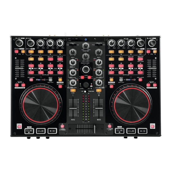
Sie online: www.omnitronic.de. Der DDC-2000 ist ein kompakter 4-Deck-MIDI-Controller mit Soundkarte für PC und Mac im Tabletop- Format. Seine Oberfläche ist perfekt angepasst für eine intuitive Bedienung von Virtual DJ und Traktor inklusive Sample-Decks. Steuerelemente für Dateiauswahl, Transport, Hotcues, Samples, Sample-Recorder, Loops, Effekte, Pitch und Videosteuerung sind ausreichend vorhanden. -
Seite 6: Bedienelemente Und Anschlüsse
BEDIENELEMENTE UND ANSCHLÜSSE Mixersektion Betriebsanzeige Zeigt den eingeschalteten Zustand des Geräts an. Eingangsanzeige INPUT 1 THRU Leuchtet, wenn die THRU-Funktion für Eingang INPUT 1 aktiviert ist, d. h. der Eingang wird direkt auf die Master-Ausgänge geschaltet anstatt auf die integrierte Soundkarte. Die Einstellung erfolgt mit dem rückseitigen Umschalter PC/THRU. - Seite 7 Regler X-FADER CURVE Regelt die Überblendcharakteristik des Crossfaders. Linke Position: weiches Überblenden (gleitender Übergang) z. B. für langlaufende Mixe. • Rechte Position: hartes Überblenden (abrupter Übergang) z. B. für Scratchen und Cutten. • Regler CUE MIXING Wählt und überblendet das Abhörsignal für den Kopfhörerausgang: Linker Anschlag CUE: Der Prefader-Pegel des Eingangskanals, dessen Taste CUE gedrückt ist, •...
-
Seite 8: Anschlüsse Herstellen
Cincheingang INPUT 1 oder die 3,5-mm-Klinkenbuchse AUX und stellen Sie den Eingangsum- schalter INPUT 1 auf die verwendete Quelle ein. AUX-Eingang 3,5-mm-Klinkenbuchse zum Anschluss eines weiteren analogen Geräts mit Line-Pegel (z. B. tragbarer MP3-Player) alternativ zum Cinch-Eingang INPUT 1. Regler INPUT 1 GAIN Zum Einstellen der Eingangsverstärkung für die Eingangsbuchsen INPUT 1 und AUX. - Seite 9 Beim Betrieb des Controllers mit einem Computer und Geräten, die über das Netzkabel geerdet sind (z. B. Verstärker), können aufgrund von Masseschleifen Brummstörungen auftreten. Um diese Störungen zu beseitigen, kann der Controller über Massetrennfilter (z. B. aus der OMNITRONIC LH-Serie) mit dem jeweiligen Gerät verbunden werden.
-
Seite 10: Asio-Treiber Installieren (Windows)
Vor der ersten Verwendung unter Windows muss zunächst die spezielle ASIO-Treibersoftware installiert werden, um die Leistung der intergierten Soundkarte des DDC-2000 zu optimieren. Der Treiber ermöglicht extrem niedrige Latenzzeiten von unter 10 ms und umfangreiche Audiokonfigurationen. Er kann für folgende WDM-kompatible Betriebssysteme verwendet werden: Microsoft Windows XP64, Vista x86/x64, 7 x86/x64. -
Seite 11: Erste Schritte Mit Virtual Dj
ERSTE SCHRITTE MIT VIRTUAL DJ Sie erhalten mit dem Kauf des DDC-2000 eine speziell auf das Gerät abgestimmte Limited Edition von Virtual DJ. Für Nutzer der Vollversion Virtual DJ PRO steht ein passendes Mapping zur Verfügung. Die nachfolgenden Abschnitte beschreiben die nötigen Schritte zur Installation und Konfiguration für beide Versionen. - Seite 12 Sie das Register [Sound-Einstellungen]. Eingänge: None Eingänge: None Ausgänge: Headphones (Master/Kopfhörer) Ausgänge: Headphones (Master/Kopfhörer) Soundkarte: ASIO Driver (DDC-2000) Soundkarte: 4-Out Card (DDC-2000) Wählen Sie die Einstellungen [Headphones] und Wählen Sie die Einstellungen [Headphones] [ASIO DRIVER] und bestätigen Sie mit und [4-Out Card] und bestätigen Sie mit [Anwenden].
- Seite 13 Virtual DJ PRO Vor der ersten Verwendung mit Virtual DJ PRO, muss die Software für den Gebrauch mit dem DDC-2000 konfiguriert werden. Schalten Sie dazu das Gerät aus und schließen Sie Virtual DJ PRO. Mapping zuweisen Windows Mapping zuweisen Mac OS Laden Sie das Mapping für Virtual DJ PRO...
- Seite 14 Audioeinstellungen Windows Audioeinstellungen Mac OS Virtual DJ PRO bietet Ihnen in Verbindung mit dem Mac OS X erkennt den DDC-2000 als externes ASIO-Treiber umfangreiche Konfigurationsmöglich- Audiogerät mit 4 Eingängen und 4 Ausgängen. keiten. Rufen Sie mit [CONFIG] das Einstellungs- Rufen Sie mit [CONFIG] das Einstellungsmenü...
- Seite 15 Eingänge: Line-Ins Eingänge: Line-Ins Ausgänge: Headphones (Master/Kopfhörer) Ausgänge: Headphones (Master/Kopfhörer) Soundkarte: DDC-2000 USB ASIO driver Soundkarte: 4-In/4-Out Card (DDC-2000) Mit dieser Konfiguration können Sie externe Audio- Mit dieser Konfiguration können Sie externe Au- diogeräte als Line-Eingänge in Virtual DJ nutzen.
- Seite 16 Funktionen unter Virtual DJ Nachdem der DDC-2000 angeschlossen und richtig unter Virtual DJ konfiguriert wurde, ist das System einsatzbereit. Wird Virtual DJ PRO verwendet, können die Bedienelemente des DDC-2000 voll ausgeschöpft werden. Für Virtual DJ LE ergeben sich einige Beschränkungen. Im Folgenden wird die komplette Funktionsbelegung unter Virtual DJ beschrieben.
- Seite 17 Bestimmt den Loop-Startpunkt. Bestimmt den Loop-Endpunkt. Der Loop wird daraufhin gestartet. ACTIVE Startet und stoppt einen Loop und Löscht einen Loop. springt zum Startpunkt. DELETE Löscht einen Loop. HOT CUE 1 Hot Cue 1 speichern und aufrufen. Titel um 4 Takte nach hinten schieben.
- Seite 18 HIGH (drücken) Zum Auslöschen der Höhen. MID (drehen) Regelt die Mitten. Ändert die Stimmlage des Titels. MID (drücken) Zum Auslöschen der Mitten. Setzt die Stimmlage zurück. KEY ON Leuchtet, wenn die Stimmlage verändert wird. LOW (drehen) Regelt die Bässe. Regelt das Filter. LOW (drücken) Zum Auslöschen der Bässe.
-
Seite 19: Gertäteeinstellungen
GERTÄTEEINSTELLUNGEN Einige Einstellungen des Geräts können über Tastenkombinationen geändert werden. Die aktuellen Einstellungen lassen sich über bestimmte LEDs anzeigen, indem Sie den linken Umschalter DECK SWITCH 3 Sekunden gedrückt halten und zusätzlich den Video-Encoder drücken. MIDI-Kanal Sie können die verwendeten MIDI-Kanäle umschalten, indem Sie den linken Umschalter DECK SWITCH 3 Sekunden gedrückt halten und zusätzlich eine der Tasten HOT CUE 1 bis 4 drücken. -
Seite 20: Midi-Meldungen
MIDI-MELDUNGEN Der Controller verwendet das MIDI-Datenprotokoll und kann deshalb auch für andere MIDI-gesteuerte Musiksoftware genutzt werden. Im Folgenden finden Sie eine umfassende Liste der MIDI-Daten, die das Gerät generiert. SHIFT + BEDIENELEMENT NOTE NOTE TASTEN & REGLER LINKES & RECHTES DECK AUTO LOOP (drehen) AUTO LOOP (drücken) C#-2... - Seite 21 NOTE LED ON LED OFF LEDs LINKES & RECHTES DECK FX 1 ON FX 2 ON D#-2 ACTIVE F#-2 DELETE HOT CUE 1 G#-2 HOT CUE 2 HOT CUE 3 A#-2 HOT CUE 4 SAMPLE 1 SAMPLE 2 C#-1 SAMPLE 3 SAMPLE 4 D#-1 KEY LOCK...
-
Seite 22: Technische Daten
TECHNISCHE DATEN DDC-2000 Allgemeine Daten Spannungsversorgung: 5 V DC, 500 mA über USB-Anschluss oder 6 V DC, 1,5 A über Netzteil (Zubehör) USB-Anschluss: 2.0, Typ B Maße: 297 x 410 x 65 mm Gewicht: 3 kg Eingänge Anschluss Eingangsimpedanz Line: Cinch L/R 47 kΩ/0 dBV... -
Seite 41: Notes
NOTES ...................................................................................................................................................................................................................................................................................................................................................................................................................................................................................................................................................................................................................................................................................... - Seite 42 ............................................................................................................................................................................................................................................................................................................................................................................................................................................................................................................................................................................................................................................................................................................................................................
- Seite 43 ............................................................................................................................................................................................................................................................................................................................................................................................................................................................................................................................................................................................................................................................................................................................................................
- Seite 44 © © © © OMNITRONIC 201 OMNITRONIC 2015 5 5 5 OMNITRONIC 201 OMNITRONIC 201 Technische Änderungen und Irrtum vorbehalten. Every information is subject to change without prior notice. 00089187.DOCX Version 1.1...