JUMO dTRANS T02 LCD Betriebsanleitung

Verwandte Anleitungen für JUMO dTRANS T02 LCD


Inhaltszusammenfassung für JUMO dTRANS T02 LCD
- Seite 1 JdTRANS T02 LCD Programmierbarer Messumformer Programmable transmitter B 70.7022.0 Betriebsanleitung Operating Manual 03.07/00384950...
- Seite 2 Bedienübersicht Normalanzeige - Messwertanzeige q > 2s q > 2s q nach letztem Parameter Parameterebene - Grenzwert Limitkomparator 1 AL1 - Grenzwert Limitkomparator 2 - Feinabgleich 0% OUtL - Feinabgleich 100 % OUtH - Teach In OFFS q > 2s q nach letztem Parameter Konfigurationsebene - Fühlerart...
-
Seite 3: Serienmäßiges Zubehör
1 Typenerklärung JUMO dTRANS T02 LCD (1) Grundausführung 707022 programmierbarer Messumformer (2) Eingang (programmierbar) Werkseitig eingestellt (Pt100 DIN in Vierleiterschaltung / 0 … 100°C) Konfiguration nach Kundenangaben (3) Ausgang (eingeprägter Gleichstrom - programmierbar) Werkseitig eingestellt (0 … 20mA) Konfiguration nach Kundenangaben (0/4 …... -
Seite 4: Installation
2 Installation Anschlussplan Setup-Schnittstelle Bitte Hinweis “Setup- Schnittstelle” auf Seite 8 beachten. Anschluss für Spannungsversorgung lt. Typenschild Analoge Eingänge Thermoelement Widerstandsthermometer in Zweileiterschaltung R =R 30Ω (R ≤ = Gesamtleitungswiderstand) Widerstandsthermometer in Dreileiterschaltung Widerstandsthermometer in Vierleiterschaltung... - Seite 5 2 Installation Potentiometer in Zweileiterschaltung 30Ω (R ≤ = Gesamtleitungswiderstand) R =R Potentiometer in Dreileiterschaltung Potentiometer in Vierleiterschaltung Widerstandsferngeber in Dreileiterschaltung Spannungseingang < 1V Spannungseingang ≥ 1V Stromeingang Analoge Ausgänge Spannungsausgang Stromausgang Strom- und Spannungsausgang sind nicht gegeneinander galvanisch ge- trennt.
- Seite 6 2 Installation Digitale Ausgänge Open-Collector-Ausgang 1 Siehe “Anschlussbeispiele” auf Seite 34. Open-Collector-Ausgang 2 Siehe “Anschlussbeispiele” auf Seite 34. Setup-Schnittstelle Die Setup-Schnittstelle und der analo- ge Ausgang sind nicht galvanisch ge- trennt. Siehe “Setup-Schnittstelle” auf Seite 8. Installationshinweise Sowohl bei der Wahl des Leitungsmaterials bei der Installation als auch beim elektrischen Anschluss des Gerätes sind die Vor- schriften der VDE 0100 „Bestimmungen über das Errichten von Starkstromanlagen mit Nennspannungen unter 1000V“...
- Seite 7 2 Installation Induktive Verbraucher (Relais, Magnetventile etc.) nicht in Gerä- tenähe installieren und durch RC- oder Funkenlöschkombina- tionen bzw. Freilaufdioden entstören. Eingangs-, Ausgangs- und Versorgungsleitungen räumlich von- einander getrennt und nicht parallel zueinander verlegen. Hin- und Rückleitungen nebeneinander führen und nach Möglichkeit verdrillen.
- Seite 8 2 Installation Setup-Schnittstelle Die Setup-Schnittstelle und der analoge Ausgang sind nicht galvanisch getrennt. Unter ungünstigen Umständen können daher, bei einem eingebauten Messumformer, Ausgleichs- ströme fließen, wenn das PC-Interface angeschlossen wird. Die Ausgleichsströme können Schäden bei den beteiligten Geräten bewirken. Keine Gefahr besteht, wenn der Ausgangsstromkreis des Messumformers galvanisch von Erde getrennt ist.
- Seite 9 2 Installation Abmessungen...
-
Seite 10: Anzeige- Und Bedienelemente
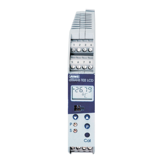
3 Anzeige- und Bedienelemente LCD-Anzeige Schnittstelle für PC-Setup-Programm Tasten zur Bedienung LEDs für Betriebszustand ohne Bedeutung, nur P = Power LED für interne Zwecke S = Status LED Betriebszustand in der Leucht-/Blinkverhalten Bedienerebene (Normalbetrieb) Limitkomparator 1 inaktiv 2 inaktiv Limitkomparator 1 aktiv 2 inaktiv Limitkomparator... - Seite 11 3 Anzeige- und Bedienelemente Betriebszustand in der Leucht-/Blinkverhalten Parameterebene (Programmier-Modus) Grenzwert von Limitkomparator 1 Grenzwert von Limitkomparator 2 Feinabgleich (Nullpunkt) Feinabgleich (Endwert) Teach In (0-%-Wert) Unterscheidung der Betriebszustände - Im Betriebszustand Bedienerebene ist die Power-LED permanent an. - Im Betriebszustand Parameterebene blinkt die Power-LED (zu gleichen Teilen an und aus).
-
Seite 12: Funktionen Und Bedienung
4 Funktionen und Bedienung Mit Hilfe der Tasten q, d und i in Verbindung mit der LCD-Anzei- ge und den in Kapitel 3 „Anzeige- und Bedienelemente“ bereits be- schriebenen Blinkzyklen der beiden LEDs „Power“ und „Status“ können Sie den Messumformer bedienen und programmieren. Bei der Bedienung unterscheiden sich drei Betriebszustände: - Bedienerebene (Normalbetrieb) - Parameterebene (Programmier-Modus) -
Seite 13: Funktionen Und Bedienung Konfigurationsebene
4 Funktionen und Bedienung Konfigurationsebene In die Konfigurationsebene gelangen Sie aus der Parameterebene durch Betätigen der Taste q (mindestens 2 Sekunden lang). Nur wenn in der Anzeige der Parameter OFFS aktiv ist und die Konfigurationsebene gestartet wird, können die Para- meter verändert werden. - Seite 14 4 Funktionen und Bedienung - Frequenz bei Messbereichsanfang C235 - Frequenz bei Messbereichsende C236 - Skalierung Startwert - Skalierung Endwert - Filterzeit - Gesamtwiderstand bei Widerstandsferngeber R FE - Simulation Istwertausgang C001 Die Konfigurationsebene wird verlassen (beendet), - nachdem Sie den letzten Parameter editiert haben oder - mindestens 20 Sekunden lang keine Taste betätigt wurde oder - die Tastenkombination q + d kurz betätigen.
-
Seite 15: Funktionen Und Bedienung Werte Erhöhen
4 Funktionen und Bedienung Werte erhöhen Beim Programmieren der Parameter dient die Taste i zum Erhöhen eines Wertes (+). Werte verringern Beim Programmieren der Parameter dient die Taste d zum Verrin- gern eines Wertes (-). Werte übernehmen Wurde eine Einstellung geändert, müssen Sie die Taste q betäti- gen, um die Änderung zu übernehmen. -
Seite 16: Funktionen Und Bedienung Grenzwerte (Limitkomparatoren) Einstellen
4 Funktionen und Bedienung Grenzwerte (Limitkomparatoren) einstellen Sie können die beiden Grenzwerte AL1 und AL2 mit Hilfe der Tasten d und i verändern. Der aktuelle Wert wird in der LCD-Anzeige dargestellt. Es erfolgt keine Ausgabe am Analogausgang. Über- nommen wird der Wert durch Betätigen der Taste q. Die Schaltdifferenzen (Hysterese) können Sie mit den Parametern C223 und C224 bzw. - Seite 17 4 Funktionen und Bedienung Funktionsweise lk8: Natürlich lassen sich alle Parameter auch mit dem als Typenzusatz erhältlichen PC-Setup-Programm einstellen. Fehlerausgang Wird der Parameter C221 auf den Wert 3 gesetzt, findet eine Über- wachung der folgenden Fehler statt: - Fühlerbruch - Fühlerkurzschluss (nur Widerstandsthermometer) - Messbereichsüberschreitung - Messbereichsunterschreitung - interne Fehler (Pt100 der Vergleichsstelle defekt, ...)
- Seite 18 4 Funktionen und Bedienung Frequenzausgang Wird der Parameter C231 auf den Wert 3 gesetzt, wird das Messsig- nal an den Klemmen des Open-Collector-Ausganges 2 als Frequenz ausgegeben (parallel zum Strom-/Spannungsausgang). Die Gren- zen des Frequenzbereiches werden durch die Parameter C235 und C236 bestimmt.
- Seite 19 4 Funktionen und Bedienung Feinabgleich (Nullpunkt und Endwert) Mit Hilfe des Feinabgleiches können Sie den Nullpunkt und die Steilheit des Ausgangssignales anpassen. Auch hier wird durch Be- tätigen der Tasten d und i der jeweilige Wert verändert und durch Betätigen der Taste q übernommen. Am Ausgang wird der gemessene Istwert ausgegeben.
- Seite 20 4 Funktionen und Bedienung Teach In Der Parameter „Teach In“ dient dazu, den 0-%-Wert festzulegen. Der am Eingang anliegende Istwert wird durch die „Teach In“-Pro- grammierung zum 0-%-Wert. Durch Betätigen der Tasten d oder i wird die Übernahme des Wertes ermöglicht und mit q durchgeführt. Nach einem Timeout ohne Übernahme steht der alte Wert wieder zur Verfügung.
-
Seite 21: Konfigurations- Und Parametertabelle
5 Konfigurations- und Parametertabelle In den folgenden Konfigurations- und Parametertabellen können Sie an der durch einen markierten Stelle (Spalte) Ihre Einstellungen protokollieren. Die werkseitige Einstellung ist durch eine graue Hin- terlegung ( ) gekennzeichnet. Parameter der Parameterebene Para- Erklärung Werte- werkseitig X meter bereich... - Seite 22 5 Konfigurations- und Parametertabelle C112 Linearisierung linear kundenspezifisch Pt 100 DIN Pt 500 DIN Pt 1000 DIN Pt 100 JIS Ni 100 Ni 500 Ni 1000 Typ „L“ Typ „J“ Typ „U“ Typ „T“ Typ „K“ Typ „E“ Typ „N“ Typ „S“...
- Seite 23 5 Konfigurations- und Parametertabelle C002 Einheit des Messwertes (nur wirksam, wenn Parameter C116 = 2 siehe Seite 27) Einheit LCD-Anzeige °C °C °F °F mbar mBAR mSEC 100ms 100mS ml/s mL/S ml/min mL/mn L/SEC l/min L/min m³/s m3/S m³/min m3/mn m³/h m3/H 1/SEC...
- Seite 24 5 Konfigurations- und Parametertabelle C002 Einheit des Messwertes (nur wirksam, wenn Parameter C116 = 2 siehe Seite 27) Einheit LCD-Anzeige µm µm ‰ ‰ µg µG µW µW mVAs mVAS...
- Seite 25 5 Konfigurations- und Parametertabelle C002 Einheit des Messwertes (nur wirksam, wenn Parameter C116 = 2 siehe Seite 27) Einheit LCD-Anzeige kVAs KVAS µJ µJ mΩ mOHM Ω kΩ KOHM MΩ MOHM mm/s mm/S mm/h mm/H m/SEC m/min m/MIN km/h Km/H m/s²...
- Seite 26 5 Konfigurations- und Parametertabelle C002 Einheit des Messwertes (nur wirksam, wenn Parameter C116 = 2 siehe Seite 27) Einheit LCD-Anzeige µA µA µS µS µH µH µF µF mm² cm² m² km² kg/l KG/L µV/K µV/K...
- Seite 27 5 Konfigurations- und Parametertabelle C114 Netzfrequenz / Temperatur-Kompensation 50Hz / interne Temperatur-Kompensation 50Hz / feste Temperatur-Kompensation 60Hz / interne Temperatur-Kompensation 60Hz / feste Temperatur-Kompensation Para- Erklärung Werte- werkseitig X meter bereich C115 Wert bei fester 0 … 100°C Temperatur- Kompensation C116 Messwert-Anzeige Prozent wie Ausgangssignal (mA oder V)
- Seite 28 5 Konfigurations- und Parametertabelle Binär-Ausgang 1 (Open-Collector-Ausgang 1) C221 Funktion des Binär-Ausganges 1 ohne Funktion Fehlerausgang Mehr Informationen entnehmen Sie bitte “Grenzwerte (Limitkomparatoren) einstellen” auf Seite 16 und “Fehlerausgang” auf Seite 17. C222 Signal des Binär-Ausganges 1 bei Fühlerbruch/-kurzschluss aktiv inaktiv unverändert Para-...
- Seite 29 5 Konfigurations- und Parametertabelle Binär-Ausgang 2 (Open-Collector-Ausgang 2) C231 Funktion des Binär-Ausganges 2 ohne Funktion Frequenzausgang Mehr Informationen entnehmen Sie bitte “Grenzwerte (Limitkomparatoren) einstellen” auf Seite 16 und “Frequenzausgang” auf Seite 18. C232 Signal des Binär-Ausganges 2 bei Fühlerbruch/-kurzschluss aktiv bzw. Frequenz C236 inaktiv bzw.
- Seite 30 5 Konfigurations- und Parametertabelle Para- Erklärung Werte- werkseitig X meter bereich C236 Frequenz bei 10 … 1000 Messbereichsende 1000Hz Weiter Parameter Para- Erklärung Werte- werkseitig X meter bereich Skalierung Startwert -1999 … +9999 Digit Skalierung Endwert -1999 … +9999 Digit Filterzeitkonstante 0.0 …...
- Seite 31 6 Hinweise ..zur Bedienung innerhalb der Parameter- und Konfigu- rationsebene Das Betätigen der Taste q als Bestätigung einer Werteinga- be setzt voraus, dass vorher ein Wert geändert wurde. Ist dies nicht der Fall, wird die Betätigung als Aufruf des nächsten Parameters angesehen.
- Seite 32 6 Hinweise ..allgemeiner Art Kann ein (oder kein) Parameter verändert werden, haben Sie vielleicht mit Hilfe des Setup-Programmes die Bedienung am Gerät verriegelt. Prüfen Sie die Einstellung durch das Setup-Programm. Nur, wenn die Ebene, in der sich der Parameter befindet, nicht verriegelt ist, kann der Parameter auch verändert wer- den.
- Seite 33 7 PC-Setup-Programm Mit dem als Typenzusatz erhältlichen PC-Setup-Programm lassen sich alle Parameter des Messumformers (inkl. der kundenspezifi- schen Linearisierung) bequem ändern. Über die Setup-Schnittstelle werden der Messumformer und der PC über das „PC-Interface“ miteinander verbunden. Konfigurierbare Parameter: - TAG-Number (10 Zeichen) - Analoger Eingang (Sensortyp) - Anschlussart (2-/3-/4-Leiterschaltung) - externe oder konstante Vergleichsstelle...
-
Seite 34: Anschlussbeispiele
8 Anschlussbeispiele Beispiel 1 Anschluss einer SPS an den Open-Collector-Ausgang Berechnungsbeispiel für R (Arbeitswiderstand) Bei dem Beispiel wird von folgenden typischen SPS-Kennwerten ausgegangen: - für Signal „1“: 13 … 30V - für Signal „0“: -3 … +5V - Eingangsstrom für Signal „1“: Bei einer angenommen Eingangsspannung von 18V/7mA für das Signal „1“... - Seite 35 8 Anschlussbeispiele Beispiel 2 Anschluss eines Relais an den Open-Collector-Ausgang...
- Seite 38 JUMO GmbH & Co. KG JUMO Mess- und Regelgeräte JUMO Mess- und Regeltechnik AG Ges.m.b.H. Hausadresse: Laubisrütistrasse 70 Moltkestraße 13 - 31 8712 Stäfa, Switzerland Pfarrgasse 48 36039 Fulda, Germany Telefon: +41 44 928 24 44 1232 Wien, Austria Lieferadresse:...