Inhaltsverzeichnis
Werbung
Verfügbare Sprachen
Verfügbare Sprachen
Quicklinks
Werbung
Inhaltsverzeichnis

Verwandte Anleitungen für Grundig GDT 2050 X


Inhaltszusammenfassung für Grundig GDT 2050 X
- Seite 1 KAMINHAUBE/ COOKER HOOD GDT 2050 X...
- Seite 3 ________________________________________________________...
- Seite 4 ________________________________________________________ DEUTSCH 05-14 ENGLISH 15-24...
- Seite 5 WARNUNGEN ______________________________________ Dunstabzugshaube erst nach der Installa- Beim Einsatz eines Gasherdes keine Brenner tion anschließen. aufgedreht lassen, wenn die Dunstabzugs- haube in Betrieb ist. Beim Herunternehmen Betriebsspannung beträgt 220 bis 240 Volt. des Kochgeschirrs vom Herd sicherstellen, Netzkabel der Dunstabzugshaube wird mit dass der entsprechende Brenner zugedreht einem nicht geerdeten Stecker geliefert.
-
Seite 6: Technische Daten
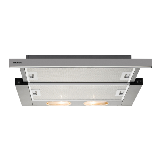
TECHNISCHE DATEN _______________________________ 1. Lampe 2. Aluminiumfilter 3. Aluminiumfiltergriff 4. Lichttaste 6. Schiebeblende 7. Perforierte Blende und synthetischer Filter 8. Perforierte Blendenklinge GDK 2050 X Breite 598 mm Tiefe 300 (geschlossene Position) 452 (offene Position) Höhe 175 mm Versorgungsspannung 220 – 240 V Wechselspannung, 50 Hz Steuerung 3 Positionen... -
Seite 7: Installation
INSTALLATION _____________________________________ Zur Installation der Dunstabzugshaube be- nötigte Produktabmessungen werden in der nachstehenden Abbildung in mm angegeben. (Abbildung 1) Dunstabzugshaube wie in Abbildung 2 gezeigt platzieren. Mit einer Schraube von 4,2 x 44,5 mm am Boden des Küchenschranks befestigen. Dunstabzugshaube installieren Die Dunstabzugshaube kann in einem Kü- chenmöbel von oben oder den Seiten instal- liert werden. - Seite 8 INSTALLATION _____________________________________ Installation von der Seite (optional): Bei dieser Anschlussmethode ist der Boden des Küchenschrank auf einer Höhe mit den Böden anderer Küchenschränke. Installation: Bereich am Küchenschrankboden entspre- chend den Abmessungen in Abbildung 3 markieren und aussägen. (Abbildung 3) (Șekil 3) Überstände an beiden Seiten der Dunstab- zugshaube entfernen.
- Seite 9 INSTALLATION _____________________________________ Nach Installation der Dunstabzugs- haube (von oben und von den Seiten): Ein für den Luftauslass der Dunstabzugshau- be geeignetes Luftauslassrohr mit dem Teil im Inneren des Küchenschranks verbinden. Das Rohr muss etwa 20 cm aus dem Kü- chenschrank herausragen, damit das An- schlussrohr, das die Luft ins Freie befördert, installiert werden kann (Abbildung 6).
- Seite 10 INSTALLATION _____________________________________ 2- Interne Zirkulation Kaminschachtan- (Umluftvariante): schluss Falls sich kein Kaminschacht in der Küche be- findet, muss die Dunstabzugshaube mit einem Geruchsfilter betrieben werden. Aktivkohlefil- ter reinigen die Luft in der Küche und geben sie in die Küche zurück. Anschluss ohne Kaminschacht Mit Abluftschacht verbinden (bei einem Rohr mit einem Durchmesser von 120 mm):...
- Seite 11 INSTALLATION _____________________________________ Aluminium-Fettfilter Dieser Filter wird mit der Dunstabzugshau- be geliefert. Er muss unabhängig von der Anschlussart (Umluft oder Abluft) verwendet werden. Die Dunstabzugshaube fängt dank des spezi- ellen Filters Fett auf. Dieser Filter besteht aus Aluminium und ist da- her abwaschbar.
-
Seite 12: Gerät Bedienen
GERÄT BEDIENEN _ __________________________________ Kontrolltasten befinden sich unter der rechten Die Gebläsemotortaste (B) hat 3 Positionen. Halterung und vorne; sie werden sichtbar, 1. Position, schwache Belüftung wenn das Schiebeteil herausgezogen wird. 2. Position, mittlere Belüftung Die Dunstabzugshaube kann mit zwei Arten 3. -
Seite 13: Wartung Und Reinigung
WARTUNG UND REINIGUNG ____________________ Reinigung und Pflege Lampe austauschen Vor der Reinigung immer den Netzstecker In der Dunstabzugshaube werden 40-W- ziehen. Sicherstellen, dass die Mittel/Uten- Halogenlampen verwendet. silien zur Reinigung des Gerätes keine Parti- Zum Austauschen der Lampen an Front- kel enthalten, die Kratzer auf den lackierten blende ziehen. -
Seite 14: Service Und Ersatzteile
Sie, sich mit Ihrem Fachhändler bzw. mit der Verkaufsstelle in Spannungsversorgung Verbindung zu setzen. Sollte dies nicht möglich Betriebsspannung: 220-240V ~ , 50Hz sein, wenden Sie sich bitte an das GRUNDIG- Service-Center unter folgenden Kontaktdaten: Technische und optische Änderungen vorbehal- TELEFON: 06102/8686893* ten! (Montag bis Freitag von 08.00 bis 17.00 Uhr) - Seite 15 WARNINGS _________________________________________ Do not plug in the hood before it is installed. Operate your appliance for a while more after the end of cooking or frying in order Operating voltage is 220 to 240 volts. to remove unpleasant smell and vapors from Power cord of your hood is supplied with an the air in the kitchen.
-
Seite 16: Technical Specifications
TECHNICAL SPECIFICATIONS _____________________ 1. Light 2. Aluminum filter 3. Aluminum filter handle 4. Lamp button 6. Sliding panel 7. Perforated panel and synthetic filter 8. Perforated panel pawl GDK 2050 X Width 598 mm Depth 300 (closed position) 452 (open position) Height 175 mm Supply voltage 220-240 V ~ 50 Hz Control... - Seite 17 INSTALLATION _____________________________________ Product dimensions required for the installation Place your hood as shown in Figure 2. of your hood is given in mm in the figure below. Secure it to the base of the cupboard with a 4.2 x 44.5 mm screw. Installation of your hood You may install your hood on your kitchen fur- niture from the top or the sides.
- Seite 18 INSTALLATION _____________________________________ Installation from sides (Optional): In this connection method, the base of the cupboard is level with the bases of other cup- boards. Installation: Mark and cut the area on the cupboard base that shall be removed as per the dimensions given in Figure 3.
- Seite 19 INSTALLATION _____________________________________ After the installation of your hood The surroundings of the pipe inside the cup- (both from the top or the sides) is board may be covered as you desire. done: Note: Connect an air outlet pipe suitable for the air The air outlet pipe shall be procured by the outlet of the hood on the part remains inside customer.
- Seite 20 INSTALLATION _____________________________________ Connection to flue (for a pipe Anti-odor filter contains charcoal (active car- bon). This filter looks like an oil trap filter, and with a diameter of 120 mm): it must be replaced every 4 months approxi- Procure a pipe with a diameter of 120, and mately depending on your usage frequency. connect one end of the pipe to the ventilation Pull the front panel to install carbon filters.
- Seite 21 INSTALLATION _____________________________________ Aluminum oil trap filter This filter is delivered with your hood. It must be used for any type of connection, whether it is with flue or not. Your oven-top hood provides oil trapping fea- ture thanks to its special filter. This filter is made of aluminum and thus, it is cleanable.
-
Seite 22: Operating The Appliance
OPERATING THE APPLIANCE _____________________ Control buttons are under the body right side Fan motor button (B) has 3 positions. bracket and in the front, and they can be seen 1st position Light ventilation when the sliding part is pulled out. You can 2nd position Medium ventilation operate your hood with two types of sliding 3rd position Fast ventilation... -
Seite 23: Maintenance And Cleaning
MAINTENANCE AND CLEANING _ ________________ Cleaning and Care Replacing the lamp Always unplug the appliance before clean- ing. Ensure that the cleaning materials that 40 W halogen lamps are used in your you will use for cleaning your appliance hood. do not contain particles that may scratch Pull the front panel to replace the lamps. -
Seite 24: Technical Data
INFORMATION_ ______________________________ Technical data This product conforms to European Directives 2004/108/EC, 2006/95/EC, 2009/125/EC and 2011/65/EU. Power supply Operating voltage: 220-240V ~ , 50Hz Technical and design modifications reserved! Environmental note The symbol on the product or on its packaging indicates that this product may not be treated as household waste. - Seite 25 BEKO Deutschland GmbH Thomas-Edison-Platz 3 63263 Neu Isenburg AUS GUTEM GRUND www.grundig.com 720119090700 13/30...