Herunterladen Inhalt Inhalt Diese Seite drucken
Inhaltsverzeichnis

Werbung

Verfügbare Sprachen

Verfügbare Sprachen

R
REMOTE CONTROL UNIT
FERNBEDIENUNGSEINHEIT
COMMANDE A DISTANCE
RM-P210
TALLY
CALL
INTERCOM
LEVEL
FULL AUTO
F1
F3
SHUTTER
BARS
F2
F4
GAIN
INSTRUCTIONS
BEDIENUNGSANLEITUNG
MANUEL D'NSTRUCTIONS
REMOTE CONTROL UNIT RM-P210
MENU/SHUTTER
GAIN
PAINT
WHITE
AUTO
MASTER BLACK
STEP
W.BAL
HIGH
B
SHUTTER
VARIABLE
MID
A
PUSH-ON
PUSH-ON
MENU
R
B
LOW
PRESET
DOWN
UP
DOWN
UP
INTRODUCTION
CONNECTION
PREPARATIONS AND
MAIN FUNCTIONS
CAMERA
ADJUSTMENTS
MENU OPERATION
GENERAL
POWER
IRIS
I
AUTO
MANU
O
CLOSE
OPEN
SC961003-002-H

Werbung

Inhaltsverzeichnis

Fehlerbehebung

loading

Inhaltszusammenfassung für JVC RM-P210

  • Seite 1 REMOTE CONTROL UNIT PREPARATIONS AND MAIN FUNCTIONS FERNBEDIENUNGSEINHEIT CAMERA COMMANDE A DISTANCE ADJUSTMENTS RM-P210 INSTRUCTIONS MENU OPERATION BEDIENUNGSANLEITUNG GENERAL MANUEL D'NSTRUCTIONS REMOTE CONTROL UNIT RM-P210 POWER TALLY CALL FULL AUTO MENU/SHUTTER GAIN PAINT WHITE AUTO MASTER BLACK IRIS SHUTTER STEP W.BAL...
  • Seite 2: Inhaltsverzeichnis

    CONNECTION NEUTRAL Example of Basic Connection .......... 7 BROWN: Example of RM-P210 (Connection of 2 units) ....8 LIVE Camera Setup ..............9 Turning the Power ON ............ 10 As the colours of the wires in the mains lead of this appara-...
  • Seite 3: Features

    Power cord Instructions PRECAUTIONS FOR PROPER USE To prolong the service life of the RM-P210, do not use it or When an intercom is used, radio interference may occa- store it in the following places. sionally affect any system that is connected to the RM-P210.
  • Seite 4: Controls, Connectors And Indicators

    INTRODUCTION CONTROLS, CONNECTORS AND INDICATORS Front panel 2 3 4 56 7 8 9 0 REMOTE CONTROL UNIT RM-P210 POWER TALLY CALL MENU/SHUTTER GAIN PAINT WHITE AUTO MASTER BLACK IRIS FULL AUTO SHUTTER STEP W.BAL HIGH SHUTTER VARIABLE AUTO PUSH-ON...
  • Seite 5 B controls . If the W.BAL switch is set to “A” or “B”, the RM-P210 outputs the colour bar signal. This signal is the white paint adjustment (fine adjustment of the R and B used during genlock operation. gain) can be performed using the R and B controls REF.
  • Seite 6: Rear Panel

    They are terminated automatically when they are not bridge-connected. The VC-P110 series camera cables that can be used to con- nect a camera to the RM-P210 are available in four lengths as [GENLOCK INPUT] connectors listed below. These connectors are used to input the VBS/BB signal for VC-P110 : 5 meters use in genlocking.
  • Seite 7: Example Of Basic Connection

    : Not usable, — : Not connectable) Viewfinder VF-P115B VF-P550B VF-P550W VF-P400 VF-P116W VF-P115 Camera VF-P116 GY-DV550 KY-D29 KY-D29W KY-27C KY-19 ● When the RM-P210 is connected to a camera, a local remote controller cannot be connected to the camera.
  • Seite 8: Example Of Rm-P210 (Connection Of 2 Units)

    AUX VIDEO INPUT GENLOCK INPUT VIDEO OUTPUT Y/C OUT R/R-Y B/B-Y COMPOSITE VIDEO CAMERA CABLE To power supply Intercom headset KA-320 Monitor Camera cable VC-P110 ● If more than three RM-P210 units are connected, the intercom volume level will be reduced.
  • Seite 9: Camera Setup

    CONNECTION CAMERA SETUP Before turning the RM-P210 on, be sure to set up the camera as shown below. GY-DV550 camera MODE switch IRIS switch “A” or “AUTO” OPERATE/WARNING LIGHT MODE RESET MONITOR INCOM SELECT COUNTER FILTER CH-1 ALARM CARBON 3200k...
  • Seite 10: Turning The Power On

    ● When an item is controllable from both the RM-210 and the camera, the control from the camera is defeated. Note that the items that are controllable from the RM-210 are variable depending on the camera models. ● When connecting the RM-P210 to the camera, do not connect a local remote controller to the camera. E-10...
  • Seite 11: Preparations And Main Functions Camera Cable Length Setup

    CAMERA CABLE LENGTH SETUP Cable length setup is required when a camera is connected to the RM-P210 for the first time or when the camera cable length is changed. The cable length setup value is stored in the memory inside the RM-P210 and is held even after it is turned OFF.
  • Seite 12: Adjustments For Genlock Operation

    Genlocking is required for a system, which uses an SEG (special effects generator) as the main signal source. REF. : “Example of RM-P210 (Connection 2 units) ” on page 8. NOTE ● The following adjustments can be made more accurately when using a vectorscope and waveform monitor.
  • Seite 13: Intercom

    INTERCOM LEVEL Earphone input impedance: 50 W to 300 W ● The RM-P210 has been set at the factory to be compat- ible with a dynamic type headset. If it is required to use a Intercom jack carbon type headset, the setting of the internal circuitry should be changed;...
  • Seite 14: Function Keys

    PREPARATIONS AND MAIN FUNCTIONS FUNCTION KEYS Up to four of the functions listed at the bottom of this page can be assigned to function keys F1 to F4 so that each function can be switched on or off by pressing the corresponding key. (For the assignment of functions: REF.
  • Seite 15: Camera Adjustments Shutter Speed Adjustment

    ● The variation range is variable depending on the cam- this time, the SHUTTER control cannot be used to vary the era in use. shutter speed. ● The shutter speed displayed on the RM-P210 may be slightly different from the actual shutter speed of the camera. GAIN ADJUSTMENT When the illumination of the object is insufficient, the electrical gain can be boosted as described below.
  • Seite 16: Iris Adjustment

    CAMERA ADJUSTMENTS IRIS ADJUSTMENT The camera lens iris can be adjusted from the RM-P210. When the lamp in the IRIS AUTO/MANU button is not lit, the iris control is set to AUTO mode, in which the iris level is controlled automatically according to the light intensity.
  • Seite 17: White Balance Adjustment

    AUTO white balance adjustment (AUTO SETUP) AUTO WHITE button Press the W.BAL switch to select memory “B” or “A”. Press the AUTO WHITE button to start the auto white- REMOTE CONTROL UNIT RM-P210 balance adjustment of the camera within a second. When POWER U/SHUTTER...
  • Seite 18: Menu Operation Flow Of Menus

    MENU OPERATION FLOW OF MENUS The menus displayed on the RM-210 are provided in the form shown below. The displayed items and values are variable depending on the connected camera model. (The items and values that are not available with the camera are not displayed.) Category Item Variable Value...
  • Seite 19: Menu Setup Method

    MENU OPERATION MENU SETUP METHOD Each menu is displayed on the LCD display and can be set up using the MENU button and the control knob. The values set in the "4: PROCESS" and "5: OPERATION" menus can be saved in files A and B. <Example of changing the camera cable length from 20 m to 100 m>...
  • Seite 20: Genlock Menu

    MENU OPERATION GENLOCK MENU This menu is used to set the camera cable length to the length actually used. ( REF. : “Adjustments for Genlock Operation” on page 12.) Item Function, Operation Available Settings Initial Setting H PHASE Adjustment of the Horizontal sync phase of genlocking. 0 to 255 SC COARSE Coarse adjustment of the colour phase of genlocking.
  • Seite 21: File Menu

    MENU OPERATION FILE MENU The values set with the menu and applied to the RM-P210 can be saved in two files named A and B. Press and hold the MENU button for 3 seconds until the FULL AUTO MENU/SHUTTER GAIN LCD display shows the menu display.
  • Seite 22: Process Menu

    MENU OPERATION PROCESS MENU This menu sets the functions built into the camera. (Some of the following items cannot be set if a local remote control unit is connected to the camera or depending on the connected camera model.) Item Function, Operation Available Settings Initial Setting...
  • Seite 23 MENU OPERATION PROCESS MENU (CONTINUED) Item Function, Operation Available Settings Initial Setting V.RESOLUTION Increases the vertical resolution. NORMAL NORMAL NORMAL : Standard value. V.MAX V.MAX : Increased value. NOTE When the vertical resolution is increased, the sensitivity deterio- rates and bright areas of objects may appear to be coloured. GAMMA ON/OFF setting of the gamma curve correction, which determines the reproduction of black.
  • Seite 24: Operation Menu

    MENU OPERATION OPERATION MENU This menu sets the functions built into the RM-P210. Item Function, Operation Available Settings Initial Setting SHUTTER Selects whether the front panel SHUTTER control varies the STEP STEP shutter speed in steps or in fine variation.
  • Seite 25: Lcd Mode Menu

    MENU OPERATION LCD MODE MENU This menu sets up the LCD display. Item Function, Operation Available Settings Initial Setting CONTRAST Adjusts the contrast of the LCD display. 5 to NORMAL NORMAL to -5 BACKLIGHT Adjusts the setting of the backlight of the LCD display. OFF : Backlight is turned off.
  • Seite 26: System Reset Menu

    MENU OPERATION SYSTEM RESET MENU This menu resets the values set by the user to the initial values. FULL AUTO MENU/SHUTTER GAIN SHUTTER STEP HIGH 1/1000 SHUTTER VARIABLE +9dB PUSH-ON PUSH-ON BARS MENU GAIN DOWN DOWN Control knob LCD display MENU button Press and hold the MENU button (approx.
  • Seite 27: Warning Messages

    GENERAL WARNING MESSAGES To prevent operational errors, the LCD display shows one of the following warning messages when an erroneous operation is performed. Displayed Message Cause Check Point INVALID ENTRY The gain is set to the LoLux mode. Exit from the LoLux mode, and then GAIN : LOLUX adjust the gain again.
  • Seite 28: Functions Available Depending On Camera Models

    BARS *1 Functions as AUTO WHITE with the KY-D29/KY-D29W. *2 Although this function is displayed it is not available. *3 The camera does not have a PVW lamp but the TALLY lamp on the RM-P210 lights in green. DETAIL (CONTOUR)
  • Seite 29: Troubleshooting

    P. 13 camera system? The RM-P210 has been set to the voltage supply at the factory. If it is required to use the TALLY input in the contact supply mode, the setting of the internal circuitry should be changed ; consult the nearest JVC-authorized service agent.
  • Seite 30: Specifications

    : 370 mA (KY-D29W + VF-P550W) Mass : 5.2 kg Operating temperatures: -5°C to 45°C Accessory : Power cord (2 m) ....1 Instructions ......1 External Dimensions (Unit: mm) REMOTE CONTROL UNIT RM-P210 POWER MENU/SHUTTER GAIN WHITE MASTER BLACK IRIS TALLY CALL...
  • Seite 31 EINFÜHRUNG ANSCHLUSS VORBEREITUNG UND HAUPTFUNKTIONEN KAMERA FERNBEDIENUNGSEINHEIT EINSTELLUNGEN RM-P210 BEDIENUNGSANLEITUNG MENÜBETRIEB ALLGEMEINES...
  • Seite 32: Einführung

    Steuertafel ..............4 Betriebserlaubnis für dieses Gerät führen. Rückseite ..............6 ANSCHLUSS Beispiel für Grundanschluss ..........7 Beispiel für RM-P210 (Anschluß von 2 Geräten) ..... 8 Dieses Gerät ist ausschließlich für professionelle Kameraeinstellung ............9 Anwendungen vorgesehen. Einschaltung POWER-Schalter ........10 VORBEREITUNG UND HAUPTFUNKTIONEN Einstellung für Kamerakabellänge .........
  • Seite 33: Besonderheiten

    Orten benutzt oder aufbewahrt werden. Funkstörungen gegelegentlich jedes System beeinflußen, Orte, die extrem hohen oder tiefen Temperaturen das an der RM-P210 angeschlossen ist. In solch einem Fall, ausgesetzt sind. sollte der INTERCOM G (GND) Anschluß der RM-P210 Orte, die starken Erschütterungen ausgesetzt sind.
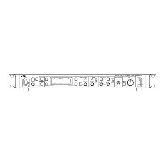
  • Seite 34: Regler, Anschlüsse Und Anzeigen

    EINFÜHRUNG REGLER, ANSCHLÜSSE UND ANZEIGEN Steuertafel 2 3 4 56 7 8 9 0 REMOTE CONTROL UNIT RM-P210 POWER WHITE MASTER BLACK IRIS TALLY CALL FULL AUTO MENU/SHUTTER GAIN PAINT AUTO SHUTTER STEP W.BAL HIGH SHUTTER VARIABLE AUTO PUSH-ON PUSH-ON...
  • Seite 35 Bei Betätigung dieser Taste, leuchtet deren Lampe auf und W.BAL-Schalter auf "A" oder "B" eingestellt ist, dann vom RM-P210 wird ein Farbbalkensignal ausgegebe. kann die Weißeinstellung (Feineinstellung der R- und B- Dieses Signal wird während Genlockbetrieb verwendet. Verstärkung) mittels den R- und B-Reglern eingestellt Siehe : "Einstellungen für Genlockbetrieb"...
  • Seite 36: Rückseite

    Brückenschaltung zu ermöglichen. Die Kamerakabel der VC-P110 Serie können für den Anschluß Sie werden automatisch abgeschlossen, wenn keine einer Kamera an die RM-P210 verwendet werden und sind in Brückenschaltung vorliegt. den folgenden vier Längen erhältlich. VC-P110 : 5 Meter [GENLOCK INPUT]-Anschlüsse...
  • Seite 37: Anschluss

    : Nicht anwendbar, — : Nicht anschließbar) Sucher VF-P115B VF-P550B VF-P550W VF-P400 VF-P115 VF-P116W Kamera VF-P116 GY-DV550 KY-D29 KY-D29W KY-27C KY-19 ● Wenn die RM-P210 an eine Kamera angeschlossen ist, kann eine lokale Fernbedienung nicht an die Kamera angeschlossen werden.
  • Seite 38: Beispiel Für Rm-P210 (Anschluß Von 2 Geräten)

    RM-P210 TALLY INTERCOM AUX VIDEO INPUT GENLOCK INPUT VIDEO OUTPUT Y/C OUT R/R-Y B/B-Y COMPOSITE VIDEO CAMERA CABLE Zor Netzversorgung Intercom-Kopfhörer KA-320 Monitor Kamerakabel VC-P110 ● Bei Anschluß von mehr als drei RM-P210 Geräten wird der Lautstärkepegel der Intercom reduziert.
  • Seite 39: Kameraeinstellung

    ANSCHLUSS KAMERAEINSTELLUNG Vor Einschaltung der RM-P210 unbedingt die Kamera einstellen, wie unten gezeigt. GY-DV550 Kamera MODE-Schalter IRIS-Schalter “A” oder “AUTO” OPERATE/WARNING LIGHT MODE RESET MONITOR INCOM SELECT COUNTER FILTER CH-1 ALARM CARBON 3200k DYNAMIC CH-2 5600k+1/8ND 5600k+1/64ND INCOM LEVEL SHUTTER STATUS...
  • Seite 40: Einschaltung Power-Schalter

    ● Wenn eine Funktion von der RM-P210 sowie der Kamera gesteuert werden kann,dann wird die Kamerasteuerung unterdrückt.Beachten, daß die mittels der RM-P210 steuerbaren Funktionen jeweils vom Kameramodell abhängen. ● Wenn die RM-P210 an die Kamera angeschlossen wird, sollte keine lokale Fernbedienung an die Kamera angeschlossen werden.
  • Seite 41: Vorbereitung Und Hauptfunktionen Einstellung Für Kamerakabellänge

    VORBEREITUNG UND HAUPTFUNKTIONEN EINSTELLUNG FÜR KAMERAKABELLÄNGE Eine Einstellung für Kabellänge ist erforderlich, wenn eine Kamera zum erstenmal an die RM-P210 angeschlosen oder wenn die Kamerakabellänge geändert wird. Der Einstellwert der Kabellänge wird im Speicher der RM-P210 gespeichert und auch nach Ausschaltung beibehalten.
  • Seite 42: Einstellungen Für Genlockbetrieb

    Bei einem System, welches einen SEG (Spezialleffektgenerator) verwendet, ist Genlockbetrieb als Hauptsignalquelle erforderlich. Siehe : "Beispiel für RM-P210 (Anschluß von 2 Geräten)" auf Seite 8. HINWEIS ● Die folgenden Einstellungen können genauer ausgeführt werden, wenn ein Vektorgraf und Wellenformmonitor verwendet wird.
  • Seite 43: Intercom

    BARS Mikrofonausgangsimpedanz: 50 W bis 100 W GAIN INTERCOM LEVEL Kopfhörereingangsimpedanz: 50 W bis 300 W ● Das RM-P210 wurde werkseitig für Kompatibilität mit einem dynamischen Kopfhörer eingestellt. Wenn ein Intercombuchse Kohlekopfhörer verwendet werden muß, dann muß die Einstellung internen Schaltung geändert...
  • Seite 44: Funktionstasten

    VORBEREITUNG UND HAUPTFUNKTIONEN FUNKTIONSTASTEN Den Funktionstasten F1 bis F4 können bis zu vier der unten auf dieser Seite aufgeführten Funktionen zugeordnet werden, so daß die einzelne Funktion jeweils durch Betätigung der entsprechenden Taste ein- oder ausgeschaltet werden kann. (Für Zuordnung der Funktionen: Siehe : Punkt 5H bis 5K bei "FUNC1" bis "FUNC4" in der BETRIEBSMENÜ-Beschreibung auf Seite 24.) Bei dem links gezeigten Beispiel sind die Funktionen <...
  • Seite 45: Kameraeinstellungen Verschlußzeiteinstellung

    Änderung der Verschlußzeit verwendet werden. HINWEIS ● Der Änderungsbereich ist je nach verwendeter Kamera änderbar. ● Die bei der RM-P210 angezeigte Verschlußzeit könnte geringfügig von der tatsächlichen Verschlußzeit der Kamera abweichen. VERSTÄRKUNGSEINSTELLUNG Wenn die Beleuchtung eines Objekts unzureichend ist, kann die elektrische Verstärkung wie unten beschrieben erhöht werden.
  • Seite 46: Blendeneinstellung

    KAMERAEINSTELLUNGEN BLENDENEINSTELLUNG Die Objektivblende der Kamera kann von der RM-P210 eingestellt werden. Wenn die Lampe der IRIS AUTO/MANU-Taste nicht aufleuchtet, ist der Blendenregler auf AUTO-Modus eingestellt, bei dem der Blendenwert automatisch entsprechend der Lichtstärke gesteuert wird. Der automatische Blendenwert kann nicht mir dem IRIS- Regler eingestellt werden.
  • Seite 47: Weißabgleicheinstellung

    "A" zu wählen. AUTO WHITE-Taste Die AUTO WHITE-Taste betätigen, um die automatische Weißabgleicheinstellung der Kamera innerhalb einer Sekunde zu beginnen. Wenn die angeschlossene Kamera eine AUTO REMOTE CONTROL UNIT RM-P210 SETUP-Funktion hat, dann die Taste betätigen und länger POWER WHITE MASTER BLACK...
  • Seite 48: Menübetrieb Menüfluß

    MENÜBETRIEB MENÜFLUSS Die bei der RM-P210 angezeigten Menüs sind wie folgt angeordnet. Die angezeigten Posten und Werte sind je nach angeschlossenem Kameramodell unterschiedlich. (Posten und Werte, die nicht für die Kamera verfügbar sind, werden nicht angezeigt.) Kategorie Posten Veränderliche Werte...
  • Seite 49: Menü-Einstellverfahren

    MENÜBETRIEB MENÜ-EINSTELLVERFAHREN Jedes Menü wird in der LCD-Anzeige angezeigt und kann mit der MENU-Taste sowie dem Steuerknopf eingestellt werden. Die bei "4: PROCESS" und "5: OPERATION" eingestellten Werte können in den Dateien A und B gespeichert werden. < Beispiel für Änderung der Kamerakabellänge von 20 m auf 100 m > Die MENU-Taste betätigen und für ca.
  • Seite 50: Genlock-Menü

    MENÜBETRIEB GENLOCK-MENÜ Mit diesem Menü wird die Kamerakabellänge auf die tatsächliche angewendte Länge eingestellt. ( Siehe : "Einstellungen für Genlockbetrieb" auf Seite 12.) Posten Funktion, Betrieb Verfügbare Einstellung Ausgangs-einstellung H PHASE Einstellung der horizontalen Synchronphase für Genlockbetrieb. 0 bis 255 SC COARSE Grobeinstellung der Farbphase für Genlockbetrieb.
  • Seite 51: File-Menü

    MENÜBETRIEB FILE-MENÜ Die mit dem Menü eingestellten und bei der RM-P210 angewendeten Werte, können in zwei Dateien mit der Bezeichnung A und B gespeichert werden. DIe MENU-Taste betätigen und für 3 Sekunden gedrückt MENU/SHUTTER GAIN FULL AUTO halten,bis in der LCD-Anzeige das Menü angezeigt wird.
  • Seite 52: Process-Menü

    MENÜBETRIEB PROCESS-MENÜ Dieses Menü stellt die eingebauten Funktionen der Kamera ein. (Einige der folgenden Posten können nicht eingestellt werden, wenn eine lokale Fernbedienung an der Kamera angeschlossenen ist oder je nach dem angeschlossenen Kameramodell.) Posten Funktion, Betrieb Verfügbare Einstellung Ausgangs-einstellung DETAIL EIN/AUS-Einstellung für Detailhervorhebungsfunktion.
  • Seite 53 MENÜBETRIEB PROCESS-MENÜ (FORTSETZUNG) Posten Funktion, Betrieb Verfügbare Einstellung Ausgangs-einstellung V.RESOLUTION Erhöhung der vertikalen Auflösung. NORMAL NORMAL NORMAL : Standardwert V.MAX V.MAX : Erhöhter Wert. HINWEIS Wenn die vertikale Auflösung erhöht wird,kann die Empfindlichkeit beeinträchtigt werden und helle Bereiche von Objekten könnten Verfärbungen aufweisen.
  • Seite 54: Operation-Menü

    MENÜBETRIEB OPERATION-MENÜ Dieses Menü stellt die eingebauten Funktionen des RM-P210 ein. Posten Funktion, Betrieb Verfügbare Einstellungen Ausgangsein-stellung SHUTTER Einstellung, ob der vorderseitige SHUTTER-Regler die STEP STEP Verschlußzeit in Schritten oder Feineinstellungn ändern soll. VARIABLE STEP : Verschlußzeitänderung in Schritten. VARIABLE: Kontinuierliche Feineinstellung bei Aufnahme eines Computermonitors, usw.
  • Seite 55: Lcd Mode-Menü

    MENÜBETRIEB LCD MODE-MENÜ Dieses Menü stellt die LCD-Anzeige ein. Posten Funktion, Betrieb Verfügbare Einstellungen Ausgangsein-stellung CONTRAST Einstellung des Kontrasts für die LCD-Anzeige. 5 bis NORMAL NORMAL bis -5 BACKLIGHT Einstellung der Hintergrundbeleuchtung der LCD-Anzeige. OFF : Hintergrundbeleuchtung wird ausgeschaltet. : Hintergrundbeleuchtung wird eingeschaltet. BACK Rückkehr zur vorherigen Anzeige.
  • Seite 56: System Reset-Menü

    MENÜBETRIEB SYSTEM RESET-MENÜ Durch dieses Menü werden die vom Anwender eingestellten Werte auf die Ausgangswerte zurückgestellt. FULL AUTO MENU/SHUTTER GAIN SHUTTER STEP HIGH 1/1000 SHUTTER VARIABLE +9dB PUSH-ON PUSH-ON BARS MENU GAIN DOWN DOWN Steuerknopf LCD-Anzeige MENU-Taste Die MENU-Taste betätigen und gedrückt halten (ca.1 6: LCD MODE Sekunden), bis das Menü...
  • Seite 57: Allgemeines Warnmeldung

    Position einstellen. AUTO BLACK LENS NOT CLOSED? Objektiv kann nicht für automatische Kamera so einstellen, daß das Objektiv Schwarzabgleicheinstellung geschlossen geschlossen werden kann. werden. AUTO BLACK ERROR! Automatische Schwarzwerteinstellung Einstellungen für die RM-P210 und funktioniert nicht einwandfrei. Kamera erneut prüfen. G-27...
  • Seite 58: Verfügbare Funktionen Entsprechend Den Verwendeten Kameras

    Sie sich bitte an Ihren örtlichen JVC Kundendienstvertreter. BARS *1 Dient bei der KY-D29/KY-D29W als AUTO WHITE-Funktion. *2 Obwohl diese Funktion angezeigt wird, ist sie nicht verfügbar. *3 Die Kamera hat keine PVW-Lampe, aber die TALLY-Lampe bei der RM-P210 DETAIL leuichtet grün auf. (CONTOUR)
  • Seite 59: Fehlersuche

    In der LCD-Anzeige wird P. 7 Sind die Kabel korrekt angeschlossen ? • ununterbrochen "NOW Sind die Netzschalter des RM-P210 und der Kamera auf ON INITIALIZING JUST A MOMENT" eingestellt ? • oder “PLEASE CHECK THE Ist der MODE (RM/VTR)-Schalter des Kameraadapters auf "RM"...
  • Seite 60: Spezifikationen

    600 W , symmetrisch Gewicht : 5,2 kg Betriebstemepratur : -5 °C bis 45 °C Zubehör : Netzkabel (2 m) ....1 Bedienungsanleitung ... 1 Außenabmessungen (Maßeinheit: mm) REMOTE CONTROL UNIT RM-P210 POWER TALLY CALL FULL AUTO MENU/SHUTTER GAIN PAINT WHITE...
  • Seite 61: Commande A Distance

    INTRODUCTION RACCORDEMENT PREPARATIFS ET FONCTIONS PRINCIPALES AJUSTEMENTS COMMANDE A DISTANCE DE LA CAMERA RM-P210 MANUEL D’INSTRUCTIONS OPERATIONS DE MENUS GENERALITES...
  • Seite 62 INTRODUCTION AVERTISSEMENT : Nous vous remercions pour votre achat de cet appareil JVC. Avant utilisation, veuillez lire ce manuel d’insructions afin POUR EVITER LES RISQUES D'INCENDIE d’obtenir les meilleures performances possibles. OU D'ELECTROCUTION, NE PAS EXPOSER Ces instructions sont prévues pour le RM-P210E.
  • Seite 63: Caractéristiques

    Si la tension d'alimentation est trop forte ou trop faible, la conséquence avant de les utiliser avec la RM-P210. vie de service de la RM-P210 peut être réduite ou elle peut Utilisez des câbles de caméra de longueur standard, comme être incapable d'assurer des performances optimales.
  • Seite 64: Commandes, Connecteurs Et Indicateurs

    INTRODUCTION COMMANDES, CONNECTEURS ET INDICATEURS Panneau avant 2 3 4 56 7 8 9 0 REMOTE CONTROL UNIT RM-P210 POWER TALLY CALL MENU/SHUTTER GAIN WHITE MASTER BLACK IRIS FULL AUTO PAINT AUTO SHUTTER STEP W.BAL HIGH SHUTTER VARIABLE AUTO PUSH-ON...
  • Seite 65 A la pression de cette touche, son témoin s’allume et la s’allume, les valeurs de gain R et B sont ajustables avec RM-P210 fournit un signal de barres de couleur, qui est les commandes R et B . Si le sélecteur W.BAL utilisé...
  • Seite 66: Panneau Arrière

    Ils sont automatiquement terminés quand ils ne sont pas Les câbles de caméra de série VC-P110 utilisables pour connectés en pont. raccorder une caméra à la RM-P210 sont disponibles en quatre longueurs comme indiqué ci-dessous: Connecteurs [GENLOCK INPUT] VC-P110: 5 mètres Servent à...
  • Seite 67: Raccordement Exemple De Raccordement De Base

    (_: Utilisable, × : Inutilisable, — : Non raccordable) Viseur VF-P115B VF-P550B VF-P550W VF-P400 VF-P116W VF-P115 Caméra VF-P116 GY-DV550 KY-D29 KY-D29W KY-27C KY-19 • Quand le RM-P210 est raccordé à la caméra, une commande à distance locale ne peut pas être raccordée à la caméra.
  • Seite 68: Exemple De Rm-P210 (Raccordement De 2 Caméras)

    AUX VIDEO INPUT GENLOCK INPUT VIDEO OUTPUT Y/C OUT R/R-Y B/B-Y COMPOSITE VIDEO CAMERA CABLE A l’alimentation secteur Casque d’intercommunication KA-320 Moniteur Câble de caméra VC-P110 ● Si plus de trois RM-P210 sont raccordées, le niveau du volume d'intercommunication sera réduit.
  • Seite 69: Implantation De La Caméra

    RACCORDEMENT IMPLANTATION DE LA CAMERA Implanter la caméra comme indiqué ci-dessous avant de mettre la RM-P210 sous tension. Caméra GY-DV550 Sélecteur MODE Sélecteur IRIS “A” ou “AUTO” OPERATE/WARNING LIGHT MODE RESET MONITOR INCOM SELECT COUNTER FILTER CH-1 ALARM CARBON 3200k...
  • Seite 70: Mise Sous Tension

    Interrupteur POWER REMARQUES ● Quand un élément est contrôlable à la fois de la RM-P210 et de la caméra, la commande de la caméra est invalidée. Notez que les éléments contrôlables de la RM-P210 varient selon les modèles de caméra.
  • Seite 71: Preparatifs Et Fonctions Principales Implantation De La Longueur Du Câble De Caméra

    IMPLANTATION DE LA LONGUEUR DU CABLE DE CAMERA L’implantation de la longueur du câble est requise quand une caméra est raccordée à la RM-P210 pour la première fois ou quand la longueur du câble de caméra a changé. La valeur d’implantation de la longueur du câble est stockée dans la mémoire de la RM-P210 et maintenue même après sa mise hors tension.
  • Seite 72: Ajustements Pour L'opération Genlock

    Le verrouillage genlock est requis pour un système qui utilise un SEG (générateur d’effets spéciaux) comme principale source de signal. REF. “Exemple de la RM-P210 (raccordement de deux caméras)”, page 8. REMARQUES ● Les ajustements ci-dessous peuvent être effectués plus précisément en utilisant un vectorscope ou un moniteur de forme d’onde.
  • Seite 73: Intercommunication

    INTERCOM Impédance d’entrée d’écouteur: 50 W à 300 W LEVEL ● La RM-P210 a été réglée à l'usine pour être compatible avec un casque de type dynamique. Si un casque de Prise d’intercommunication type carbone doit être utilisé, le réglage des circuits internes doit être modifié.
  • Seite 74: Touches De Fonction

    PREPARATIFS ET FONCTIONS PRINCIPALES TOUCHES DE FONCTION Quatre maximum des fonctions énumérée en bas de cette page peuvent être assignées aux touches de fonction F1 à F4 de sorte que chaque fonction puisse être activée ou désactivée en appuyant sur la touche correspondante.
  • Seite 75: Ajustements De La Camera Ajustement De La Vitesse D'obturation

    REMARQUES ● La plage de variation varie selon la caméra utilisée. ● La vitesse d'obturation affichée sur la RM-P210 peut légèrement différer de la vitesse d'obturation réelle de la caméra. AJUSTEMENT DU GAIN Quand l’illumination du sujet est trop faible, le gain électrique peut être augmenté...
  • Seite 76: Ajustement De L'iris

    AJUSTEMENTS DE LA CAMERA AJUSTEMENT DE L’IRIS L’iris de l’objectif de la caméra est ajustable à partir de la RM-P210. Quand le témoin de la touche IRIS AUTO/MANUAL est éteint, la commande iris est réglée au mode AUTO, dans lequel le niveau d’iris est automatiquement contrôlé selon l’intensité...
  • Seite 77: Ajustement De La Balance Du Blanc

    Touche AUTO WHITE mémoire “B” ou “A”. Appuyez sur la touche AUTO WHITE pour démarrer l’ajustement automatique de la balance du blanc de la REMOTE CONTROL UNIT RM-P210 caméra dans la seconde. Quand la caméra raccordée a POWER U/SHUTTER GAIN...
  • Seite 78: Operations De Menus Organigramme Des Menus

    OPERATIONS DE MENUS ORGANIGRAMME DES MENUS Les menus affichés sur la RM-P210 sont divisés sous la forme ci-dessous. Les postes et valeurs affichés sont variables selon le modèle de la caméra raccordée. (Les postes et valeurs non disponibles ne sont pas affichés.) Catégorie...
  • Seite 79: Méthode D'implantation Des Menus

    OPERATIONS DE MENUS METHODE D’IMPLANTATION DES MENUS Chaque menu apparaît sur l’affichage LCD et peut être implanté avec la touche MENU et la commande. Les valeurs réglées dans les menus “4: PROCESS” et “5: OPERATION” peuvent être sauvegardées dans les fichiers A et B. <Exemple de changement de longueur du câble de caméra de 20 à...
  • Seite 80: Menu Genlock

    OPERATIONS DE MENUS MENU GENLOCK Ce menu s’utilise pour régler la longueur du câble de caméra à la longueur actuellement utilisée. REF. : “Ajustements pour l’opération GENLOCK”, page 12. N˚ Poste Fonction, opération Réglages disponibles Réglage initial H PHASE Ajustement de la phase de synchro horizontale du verrouillage 0 à...
  • Seite 81: Menu File

    OPERATIONS DE MENUS MENU DE FILE Les valeurs réglées avec le menu et appliquées à la RM-P210 peuvent être sauvegardées dans deux fichiers appelés A et B. Pressez la touche MENU 3 secondes jusqu’à ce que FULL AUTO MENU/SHUTTER GAIN...
  • Seite 82: Menu Process

    OPERATIONS DE MENUS MENU PROCESS Ce menu règle les fonctions intégrée à la caméra. (Certains des postes suivants ne sont pas réglables si une commande à distance est raccordée à la caméra ou selon le modèle de la caméra raccordée.) N˚...
  • Seite 83 OPERATIONS DE MENUS MENU PROCESS (SUITE) N˚ Poste Fonction, opération Réglages disponibles Réglage initial V.RESOLUTION NORMAL NORMAL Augmente la résolution verticale. NORMAL : Valeur standard. V.MAX V.MAX : Valeur augmentée. REMARQUE A l’augmentation de la résolution verticale, la sensibilité se dégrade et les zones lumineuses des sujets peuvent apparaître colorées.
  • Seite 84: Menu Operation

    OPERATIONS DE MENUS MENU OPERATION Ce menu règle les fonctions intégrée à la RM-P210. N˚ Poste Fonction, opération Réglages disponibles Réglage initial SHUTTER Sélectionnez si la commande SHUTTER du panneau avant varie STEP STEP la vitesse d’obturation par paliers ou par variation précise.
  • Seite 85: Menu Lcd Mode

    OPERATIONS DE MENUS MENU LCD MODE Ce menu implante l’affichage LCD. N˚ Poste Fonction, opération Réglages disponibles Réglage initial CONTRAST Ajuste le contraste de l’affichage LCD. 5 à NORMAL NORMAL à -5 BACKLIGHT Ajuste le rétro-éclairage de l’affichage LCD. OFF : Le rétro-éclairage est hors service. : Le rétro-éclairage est en service.
  • Seite 86: Menu System Reset

    OPERATIONS DE MENUS MENU SYSTEM RESET Ce menu réinitialise les valeurs réglées par l’utilisateur aux valeurs initiales. FULL AUTO MENU/SHUTTER GAIN SHUTTER STEP HIGH 1/1000 SHUTTER VARIABLE +9dB PUSH-ON PUSH-ON BARS MENU GAIN DOWN DOWN Commande Affichage LCD Touche MENU Appuyez sur la touche MENU (env.
  • Seite 87: Generalites Messages D'avertissement

    GENERALITES MESSAGES D’AVERTISSEMENT Pour éviter les erreurs de fonctionnement, l’affichage LCD indique un des messages d’avertissement suivants en cas d’opération erronée. Message affiché Cause Contrôle à faire INVALID ENTRY Le gain est réglé au mode LoLux. Quittez le mode LoLux, puis ajustez à GAIN : LOLUX nouveau le gain.
  • Seite 88: Fonctions Disponibles Selon Les Modèles De Caméra

    JVC le plus proche pour les détails. *1 Fonctions telles que AUTO WHITE avec le KY-D29/KY-D29W. *2 Bien qu’affichée, cette fonction n’est pas disponible. DETAIL *3 La caméra n’a pas de témoin PVW, mais le témoin TALLY du RM-P210 (CONTOUR) s’allume en vert. F-28...
  • Seite 89: Dépannage

    P. 13 s’allume pas. celui de la caméra? La RM-P210 a été réglée à la tension d'alimentation à l'usine. Si l'entrée TALLY doit être utilisée en mode d'alimentation par contact, le réglage des circuits internes doit être modifié. Consultez l'agent de service agréé JVC le plus proche.
  • Seite 90: Caracteristiques Techniques

    : 5,2 kg Intercommunication symétrique Températures de fonctionnement : -5˚C à 45˚C Accessoires : Cordon d’alimentation (2 m) ..1 Manuel d’instructions ..... 1 Dimensions extérieures (unité: mm) REMOTE CONTROL UNIT RM-P210 POWER TALLY CALL FULL AUTO MENU/SHUTTER GAIN PAINT...
  • Seite 91 is a registered trademark owned by Victor Company of Japan, Limited. is a registered trademark in Japan, the U.S.A., the U.K. and many other countries. Printed in Thailand © 2005 Victor Company of Japan, Limited. SC961003-002-H...

Inhaltsverzeichnis