Ismatec ISM 919 Betriebsanleitung
Inhaltsverzeichnis
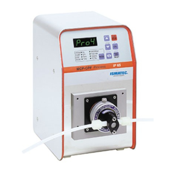
MCP-CPF Process
Betriebsanleitung
Ventillose
Taumelkolben-
Dosierpumpe
Mikroprozessor-gesteuert
ISM 919
Schutzgrad IP 65
Antrieb ohne Pumpenkopf
für Pumpenköpfe
RH00
RH0
RH1
QP.QO
QP.Q1
QP.Q2
QP.Q3
DEUTSCH
Operating Manual Mode d'emploi
Valveless
Rotary Piston
Dispensing Pump
Microprocessor controlled
ISM 919
Protection rating IP 65
Drive without pump-head
for pump-heads
RH00
RH0
RH1
QP.QO
QP.Q1
QP.Q2
QP.Q3
ENGLISH
Pompe doseuse
piston rotative
sans soupape
Commandé par
microprocesseur
ISM 919
Classe de protection IP 65
Moteur sans tête de pompe
pour têtes de pompe
RH00
RH0
RH1
QP.QO
QP.Q1
QP.Q2
QP.Q3
FRANÇAIS
Inhaltsverzeichnis

Verwandte Anleitungen für Ismatec ISM 919


Inhaltszusammenfassung für Ismatec ISM 919
- Seite 1 Dosierpumpe Dispensing Pump sans soupape Mikroprozessor-gesteuert Microprocessor controlled Commandé par microprocesseur ISM 919 ISM 919 ISM 919 Schutzgrad IP 65 Protection rating IP 65 Classe de protection IP 65 Drive without pump-head Antrieb ohne Pumpenkopf Moteur sans tête de pompe for pump-heads für Pumpenköpfe...
- Seite 2 DIESE SEITE WURDE BEWUSST LEER GEHALTEN. THIS PAGE INTENTIONALLY LEFT BLANK. CETTE PAGE A ÉTÉ INTENTIONNELLEMENT LAISSÉE VIDE.
- Seite 3 Entretien. Auf Kolbenbrüche gewähren wir by our warranty. après usage keine Garantie. Les bris de pistons sont exclus de la garantie fournie par ISMATEC ® MCP-CPF PROCESS, 14-017, REV. C MCP-CPF PROCESS, 14-017, REV. C 3 of 65...
-
Seite 4: Inhaltsverzeichnis
Inhaltsverzeichnis Contents Sommaire Sicherheitsvorkehrungen Safety precautions Mesures de sécurité Garantiebestimmungen Warranty terms Conditions de garantie Produkt Product Produit Geräterückwand Rear panel Tableau arrière Netzspannung Mains voltage Tension d’alimentation Inbetriebnahme Starting the pump Mise en route Startinformation Start-up information Informations de mise en route Operating panel Tableau de commande Bedienungspanel... - Seite 5 Contents Sommaire Inhaltsverzeichnis Anzahl Dosierzyklen Number of dispensing cycles Nombre de cycles de dosage Tropfenfreies Dosieren Drip-free dispensing Dosage sans goutte Achtung Pumpen gegen Druck Pumping against pressure Pompage contre pression Bei beruhrung des rotierenden Wenn die Pumpe ruht When the pump is idle Durant les temps d'arrêt pumpenkopfes besteht quetsch/ verletzungsgefahr.
-
Seite 6: Sicherheitsvorkehrungen
Sicherheitsvorkehrungen Safety precautions Mesures de sécurité Die ISMATEC Keramik-Kolben- ISMATEC ceramic piston pumps are Les pompes à piston rotatif ISMATEC ® ® ® pumpen sind für Förder- und designed for pumping and dispensing sont prévues pour l’usage en Dosieraufgaben in Labor und Industrie applications in laboratories and laboratoire et dans l’industrie. -
Seite 7: Mesures De Sécurité
Aggressive Medien Les bris de pistons sont exclus de la Corrosive liquids Das Pumpen aggressiver Medien kann garantie fournie par ISMATEC ® bei den Dichtungen im Pumpenkopf Corrosive liquids may eventually zu Lecks führen. Liquides corrosifs produce leak paths around the sealing surfaces of the pump-head. - Seite 8 For service and repairs carried der potentiellen Gefahren bewussten Les réparations ne doivent être out by the customer or by third- Fachkraft ausgeführt werden. effectuées que par une personne party companies ISMATEC ® denies connaissant parfaitement les risques Durch Kunden bzw. Drittpersonen any responsibility.
-
Seite 9: Garantiebestimmungen
Pour toute demande, veuillez prendre elektrospezifisch unter Bedingungen contact avec votre représentant ISMATEC l’environnement et des spécifications ® use of third-party software, hardware, eingesetzt wird, für die es nicht électriques définies pour le produit... -
Seite 10: Produkt
Antrieb MCP-CPF Process MCP-CPF Process drive Moteur MCP-CPF Process inkl. MagnetBestell-Nr. ISM 919 Magnet included Order No. ISM 919 aimant inclu No de commande ISM inkl. fest montiertem Netz-kabel, incl. integrated power cord, 2 m long, 919 y compris câble réseau fixe Länge 2 m, mit Geräte-kupplung... -
Seite 11: Geräterückwand
Geräterückwand Rear panel Tableau arrière 1. Netzschalter (ein/aus) 1. Mains switch (on/off) 1. Commutateur principal 2. Netzkabel 2. Power cord 2. Prise d’alimentation 3. RS232 IN (Eingang, weiblich) 3. RS232 IN (female) 3. RS232 IN (entrée femelle) 4. RS232 OUT (Ausgang,männlich) 4. -
Seite 12: Inbetriebnahme
Inbetriebnahme Starting the pump Mise en route Pumpe am Netz anschließen und mit Connect the pump to the mains Raccorder la pompe au réseau dem Netzschalter einschalten. and switch it on with the power et mettre en route avec supply switch. l’interrupteur de réseau. -
Seite 13: Bedienungspanel
Bedienungspanel Operating panel Tableau de commande 1. Digitale LED-Anzeige 1. Digital LED display 1. Affichage LED 2. Wert reduzieren 2. Reduce value 2. Réduire la valeur settings settings settings 3. Wert erhöhen 3. Increase value 3. Augmenter la valeur 4. RUN/STOP 4. - Seite 14 Bedienungspanel Operating panel Tableau de commande 7. Drehrichtung 7. Rotation direction 7. Sens de rotation Wechselt die Drehrichtung Changes the rotation direction Change le sens de rotation. A chaque changement du sens Bei jedem Drehrichtungswechsel Each time the rotation direction is de rotation, TOTAL est remis à...
-
Seite 15: Grundeinstellungen
Grundeinstellungen wählen Selecting the basic settings Choisir les réglages de base 1. Programm wählen (Seite 19) 1. Select the program Page 19) 1. Choisir le programme Page 19) 2. Pumpe ausschalten 2. Switch the pump OFF 2. Déclencher la pompe 3. - Seite 16 Programmspezifische Program specific Réglages de base Grundeinstellungen basic settings spécifiques au programme Für jedes der 4 Programme Individually adjustable for each of Réglage individuel possible pour individuell einstellbar. the 4 programs. chacun des 4 programmes. Cycles Cycles Cycles Anzahl Dosierungen nach Volumen bzw. Number of dispensing steps by time or Nombre des distributions selon le nach Zeit, 0..9999...
- Seite 17 Programmspezifische Program specific Réglages de base Grundeinstellungen basic settings spécifiques au programme Für jedes der 4 Programme Individually adjustable for each of Réglage individuel possible pour individuell einstellbar. the 4 programs. chacun des 4 programmes. Fußschalter Pédale de commande, Footswitch Toggle (default value) Toggle (Default-Wert) Toggle (valeur par défaut)
-
Seite 18: Allgemeine Grundeinstellungen
Allgemeine Grundeinstellungen General basic settings Réglages généraux de base Gelten für alle 4 Programme Valid for all 4 programs. Valables pour chacun des 4 gemeinsam. programmes. Initializing 4 Initialisierung 4 Initialisation 4 Pressing the ok key resets all basic settings Durch Drücken der Taste ok werden in all 4 programs to the default values: En pressant la touche ok, tous les réglages... -
Seite 19: Programmwahl
Programmwahl Selecting the program Sélection du programme Beim Einschalten wählt die Pumpe When switching the pump on, it always Lors de l’enclenchement de la pompe, immer das zuletzt benutzte Programm. selects the previously used program. cette dernière choisit toujours le dernier programme utilisé. -
Seite 20: Hubvolumen Einstellen
Hubvolumen einstellen Setting the stroke volume Réglage du volume de course Typ/Type RH Pumpenköpfe/ Pump-heads/ Têtes de pompe Einstellung des Hubvolumens über Enter the stroke volume in the settings Entrer le volume de course dans le menu Menü Grundeinstellungen (settings), menu (see basic settings, Page 15). - Seite 21 Hubvolumen einstellen Setting the stroke volume Hubvolumen einstellen STROKE PROGRAM PUMP Flow rate DISP Time Volume ID-Code des montierten Pum- Check and, if necessary, enter the Contrôler, respectivement saisir le PAUSE Time TOTAL penkopfes kontrollieren bzw. eingeben ID code of the mounted pump-head code ID de la tête de pompe installée (Seite 16).
-
Seite 22: Rh-Pumpenkopf
RH-Pumpenkopf RH pump-heads Tête de pompe RH STROKE PROGRAM Nullpunkt-Kalibrierung Zero point calibration Calibration du point zéro PUMP Flow rate DISP Time Volume Die Kalibrierung des Skalen 0-Punktes Before using the pump the first time, Nous recommandons de calibrer le PAUSE Time TOTAL... -
Seite 23: Nach Fließrate
Pumpen nach Fließrate Pumping by flow rate Pompage selon le débit STROKE PROGRAM PUMP Flow rate DISP Time Volume 1. Mit der MODE-Taste auf 1. Change the mode to PUMP Flow rate. 1. Passer avec la touche MODE sur PAUSE Time TOTAL PUMP Flow rate wechseln. -
Seite 24: Fließrate Kalibrieren
Fließrate kalibrieren Calibrating the flow rate Calibration du débit STROKE PROGRAM PUMP Flow rate DISP Time Volume ID-Code des montierten Pum- Check and, if necessary, enter the Contrôler, respectivement saisir le PAUSE Time TOTAL penkopfes kontrollieren bzw. ID code of the mounted pump-head code ID de la tête de pompe installée eingeben (Seite 16). -
Seite 25: Nach Drehzahl
Pompage selon le Pumpen nach Drehzahl Pumping by speed STROKE PROGRAM nombre de tours PUMP Flow rate DISP Time Volume 1. Mit der MODE-Taste auf 1. Change mode to PUMP rpm. The 1. MODE sur PUMP rpm réglable PAUSE Time TOTAL PUMP rpm wechseln, digital speed is digitally adjustable in steps of... -
Seite 26: Standby-Betrieb
Standby-Betrieb Stand-by mode Fonctionnement en stand-by STROKE PROGRAM PUMP Flow rate DISP Time Volume Diese Funktion empfiehlt sich, um The purpose of this mode is to prevent Cette fonction est recommandée PAUSE Time TOTAL z.B. über Nacht ein Austrocknen the pump-head and the tubing system pour éviter que la tête de pompe et from drying out (e.g. -
Seite 27: Dosieren Nach Volumen
Dosieren nach Volumen Dispensing by volume Dosage selon le volume STROKE PROGRAM PUMP Flow rate DISP Time Volume ID-Code des montierten Check and, if necessary, enter the Contrôler, respectivement saisir le PAUSE Time TOTAL Pumpenkopfes kontrollieren bzw. ID code of the mounted pump-head code ID de la tête de pompe eingeben (Seite 16). -
Seite 28: Dosiervolumen Kalibrieren
Volumen kalibrieren Calibrating the volume Calibration du volume STROKE PROGRAM PUMP Flow rate DISP Time Volume ID-Code des montierten Pum- Check and, if necessary, enter the Contrôler, respectivement saisir le PAUSE Time TOTAL penkopfes kontrollieren bzw. ID code of the mounted pump-head code ID de la tête de pompe installée eingeben (Seite 16). -
Seite 29: Default-Kalibration Fließrate
Default-Kalibration Fließrate Default calibration of flow rate Calibration par défaut (débit) STROKE PROGRAM PUMP Flow rate DISP Time Volume 1. Mit der MODE-Taste auf 1. Change the mode to 1. Passer avec la touche MODE sur PAUSE Time TOTAL PUMP Flow rate. PUMP Flow rate. -
Seite 30: Dosieren Nach Zeit
Dosieren nach Zeit Dispensing by time Dosage selon le temps STROKE. PROGRAM PUMP Flow rate DISP Time Volume The dispensing time can be La durée de dosage peut être définie Die Dosierzeit kann von 0.10 s – PAUSE Time TOTAL entered from 0.10 s –... -
Seite 31: Volumendosierung In Einer Zeiteinheit
Volumendosierung Dispensing by volume Dosage d'un volume dans un STROKE. PROGRAM in einer Zeiteinheit within a pre-set time intervalle de temps donné PUMP Flow rate DISP Time Volume 1. Mit der MODE-Taste auf DISP 1. Change the mode to DISP Time. 1. -
Seite 32: Intervall-Dosieren (Volumen)
Intermittent dispensing Dosage par intervalles Intervall-Dosieren (Volumen) STROKE. PROGRAM (by volume) (selon volume) PUMP Flow rate DISP Time Volume Repetitives Dosieren nach Intermittent dispensing by volume Dosage répétitif selon le volume avec PAUSE Time TOTAL Volumen mit Pause with a pause un temps de pause prédéfini 1. -
Seite 33: Intervall-Dosieren (Zeiteinheit)
Intermittent dispensing Dosage par intervalles Intervall-Dosieren (Zeiteinheit) STROKE PROGRAM (by time) (unité de temps) PUMP Flow rate DISP Time Volume Repetitives Dosieren nach Zeit mit Intermittent dispensing by time with Dosage répétitif selon le temps avec PAUSE Time TOTAL vorgegebener Pausenzeit a pre-set pause time un temps de pause prédéfini. -
Seite 34: Anzahl Dosierzyklen
Anzahl Dosierzyklen Number of dispensing cycles Nombre de cycles de dosage aus/off auf Rückwand on rear panel sur panneau arrière Beim Dosieren in Intervallen (nach The number of dispensing cycles Lors du dosage par intervalles Zeit bzw. Volumen) kann die Anzahl can be entered when dispensing at (selon le temps, resp. -
Seite 35: Tropfenfreies Dosieren
Tropfenfreies Dosieren Drip-free dispensing Dosage sans goutte aus/off auf Rückwand Mit programmierbaren Kolbenhub- Reverse piston strokes (back-steps) Un dosage sans goutte peut être on rear panel sur panneau arrière Rückschritten (1 – 100 Kolbenhübe) allow drip-free dispensing (1 – 100 effectué... -
Seite 36: Pumpen Gegen Druck
Pumpen gegen Druck Pumping against pressure Pompage contre pression Je nach Pumpenkopf kann die MCP-CPF Depending on tne pumpe head Selon la tête de pompe et en exploitation Process im Dauerbetrieb bis max. 6.9 bar the MCP-CPF Process can be used continue, la pompe MCP-CPF Process Differenzdruck eingesetzt werden. -
Seite 37: Analogschnittstelle
Analogschnittstelle Analog interface Interface analogique speed IN direction input 1 start +26 V Pin 1, GND (Masse) Pin 1, GND (ground) Pin 1, GND (masse) remote input 2 Mit dem Schutzleiter verbundene Connected to the protective earth Connecté à la mise à terre. Potentiel de Masse. - Seite 38 Analogschnittstelle Analog interface Interface analogique Pin 9, speed OUT Pin 9, speed OUT Pin 9, speed OUT Die werkseitige Einstellung ist 0 – 10 The default setting is 0 – 10 V Le réglage d’usine par défaut est 0 – 10 Hinweis , proportional zur Motordrehzahl.
- Seite 39 Schalter S1 Switch S1 Switch S1 4/SAT Pins FS toggle Impedanz DIP-Switch 1 DIP-Switch 2 DIP-Switch 3 DIP-Switch 4 DIP-Switch 5 0-5 V 470 kΩ OFF* OFF* OFF* 1.6 AF Eingang 0-10 V 2 kΩ Pin 5 Input/Entrée speed IN 0-20 mA 240 Ω...
-
Seite 40: Serielle Schnittstelle
Die Adressierung ermöglicht die The assignment of the address enables d’une seule et même interface RS232. Ansteuerung von bis zu 8 ISMATEC the user to control up to 8 ISMATEC ® ® Le moteur MCP-CPF Process a un retard de Pumpen mit einer RS232-Schnittstelle. -
Seite 41: Rs232 Out
Serielle Schnittstelle Serial interface Interface sérielle RS232 OUT (Ausgang; männl.) RS232 OUT (male) RS232 OUT (sortie; mâle) Pin 2: RS232 Rx Pin 2: RS232 Rx Pin 2: RS232 Rx Dient zusammen mit Pin 3/5 zum Is used for connecting additional Employé... - Seite 42 Serielle Schnittstelle Serial interface Interface sérielle Pumpensoftware Version/ Pump software version/ Version du logiciel de la pompe 1.01 Zeichenerklärungen / Key to the symbols / Explications des signes * Eingabe richtig/Correct input/Saisie correcte # Eingabe falsch/Incorrect input/Saisie erronée _ _ _ _ Ziffern zwischen 0–9/Numerals between 0–9/Chiffres entre 0–9 ASCII 10 Zeilenschaltung/ Line feed/Nouvelle ligne...
- Seite 43 Serielle Schnittstelle Interface sérielle Serial interface Befehl Funktion / Beschreibung Beispiel Antwort Beispiel Command Function / Description Example Response Commande Fonction / Description Exemple Réponse Zahlen für Bedienfeld schreiben (nur bei inaktivem Bedienfeld sichtbar, siehe Befehl B) 1D-12.3 13 Writing numbers for control panel (only visible if control panel is inactive, see command B) D _ _ _ _ _ 1D12.34 13 Ecrire les chiffres pour le panneau de commande (visible uniquement lorsque...
- Seite 44 Serielle Schnittstelle Serial interface Interface sérielle Befehl Funktion / Beschreibung Beispiel Antwort Command Function / Description Response Example Commande Fonction / Description Réponse Exemple Eingabe: Pumpenschlauch Innendurchmesser (in 1/100 mm) +_ _ _ _ Input: Pump tubing inner diameter (in 1/100 mm) 1+0320 13 Saisie: Diamètre intérieur du tube de pompe (en 1/100 mm)
- Seite 45 Serielle Schnittstelle Serial interface Interface sérielle Befehl Funktion / Beschreibung Beispiel Antwort Command Function / Description Response Example Commande Fonction / Description Réponse Exemple Abfrage: Kolbenhübe für »MODE DISP Volume« Inquiry: Piston strokes for »MODE DISP Volume« 1U 13 100 1310 Interrogation: Courses de piston pour »MODE DISP Volume«...
- Seite 46 Serielle Schnittstelle Serial interface Interface sérielle Befehl Funktion / Beschreibung Beispiel Antwort Command Function / Description Response Example Commande Fonction / Description Réponse Exemple Pausenzeit (Antwort in 1/10 Sek.) Abfrage: 1T 13 20 1310 Inquiry: Pause time (Reply in 1/10 sec.) Interrogation: Temps de pause (réponse en 1/10 sec.) 1) Für Eingabe in...
- Seite 47 Serielle Schnittstelle Serial interface Interface sérielle Befehl Funktion/ Beschreibung Beispiel Antwort Command Function / Description Example Response Commande Fonction / Description Exemple Réponse Ein- und Ausgänge/ Inputs and Outputs/ Entrées et sorties Abfrage: Eingang 1 (Pin 6) Eingang offen: - Eingang auf Masse: + Inquiry: Input 1 (pin 6) input open: - input grounded: + 1.
-
Seite 48: Kaskadierung Mehrerer Pumpen
Pumpen / pumps / pompes Sofern Sie über eine entsprechende Providing that an appropriate software Si vous êtes en possession d‘un Software verfügen, können bis max. 8 is available, up to 8 ISMATEC pumps logiciel adéquat, il vous est possible ® ISMATEC ®... -
Seite 49: Programmier-Software
- Treiber LabVIEW ® - Driver Pilotes LabVIEW ® 0.5 m Die aktuellen Treiber für Ihre ISMATEC The current drivers for your ISMATEC Vous pouvez télécharger les pilotes ® ® - Pumpe finden sie unter: pump can be downloaded from our actuels de votre pompe ISMATEC ®... -
Seite 50: Progedit
3 1/2" floppy drive, Win95 or higher, Exigences posées au système: Pentium oder höher. Pentium or higher. Lecteur de disquette 31/2", Win95 ou supérieur, Pentium ou plus Gratis-Vollversion Free full version www.ismatec.com www.ismatec.com Vérsion complét gratuit www.ismatec.com Downloads Downloads Downloads SOF104 ProgEdit MCP-CPF PROCESS, 14-017, REV. -
Seite 51: Fließraten-Tabellen
Fließraten-Tabellen Flow rate charts Tableaux des débits ID-Code* rH00 ID-No. ** Zur Erreichung der max. Fließraten ist das Hubvolumen auf den Maximalwert (je nach Pumpenkopf) einzustellen. Hubvolumen/ stroke volume/ max. 25 µl max. 25 µl max. 25 µl max. 25 µl max. -
Seite 52: Têtes De Pompe
Pumpenköppfe Pump-heads Têtes de pompe Differenzdruck Spülanschluss Ein- / Auslass Pumpenkopf Bestell-Nr Zylindergehäuse Mediumbenetzte Zylinder diff. pressure Teile Gland flow Kolben Temperatur Main flow ports Pump-head Oder No. Cylinder case Cylinder ports Pression Wetted parts Piston max. Raccords Tête de Boîtier du différentielle Cylindre... -
Seite 53: Zubehör
Zubehör Accessories Accessoires PTFE Schläuche PTFE Tubing Tubes PTFE 1.6 mm IØ 1.6 mm (1/16") I.D. 1.6 mm diam. int. 3.2 mm aØ 3.2 mm (1/8") o.d. 3.2 mm diam. ext. mit 2 Fittings with 2 fittings avec 2 raccords UNF 1/4–28 (männlich) UNF 1/4–28 (male) UNF 1/4–28 (mâle) -
Seite 54: Verbindungskabel
Zubehör Accessories Accessoires Verbindungskabel Connecting cable Câble de liaison Für Verbindung zwischen einem PC For connecting an MCP-CPF Process to Pour liaison avec une fiche RS-232 mit einem 9-poligen Stecker und einer a PC via the 9-pin RS232 connector. à 9 pôles entre un PC et une MCP-CPF Process Order No. -
Seite 55: Abnehmen Der Gehäusehaube
Abnehmen der Gehäusehaube Removing the casing hood Ouverture du boîtier Um die Dichtigkeit des Gehäuses In order to maintain the best Afin de garantir l’étanchéité du zu gewährleisten, empfehlen wir, die possible seal of the casing, the pump boîtier, il est recommandé de n’ouvrir la Pumpe nur für das Ersetzen einer should only be opened for replacing pompe que pour remplacer un fusible... -
Seite 56: Stecker-Abdichtung
Abnehmen der Gehäusehaube Removing the casing hood Ouverture du boîtier Abdichten der Haube Sealing the casing hood Etanchement du capot Wenn die Haube gut sitzt, muss When the casing hood fits tight, each Lorsque le capot est bien en place, jede Schraube (einzeln!) erneut single screw must be removed again and chaque vis (une à... -
Seite 57: Auswechseln Der Sicherungen
Auswechseln der Sicherungen Changing the fuses Remplacement des fusibles Die Sicherungen sind auf dem The fuses are fixed to the control board Les fusibles sont fixés sur le tableau de Steuerprint (oben) und auf dem (above) and the power supply print commande (dessus) et sur le tableau Netzteilprint (unten) wie nebenstehend (below) as illustrated opposite. -
Seite 58: Unterhalt/Reparaturen
Beschreibung des Defekts an to your ISMATEC distributor. Please détaillée du défaut constaté à votre ® Ihre ISMATEC ® -Vertretung. Bitte use the original ISMATEC ® packing or a revendeur ISMATEC ® . Veuillez employez Entsorgung verwenden Sie die Original- oder packet of equal quality. -
Seite 59: Travaux De Réparation
H-00CKC-LF FMI 311 H-00CKC-LF FMI 311 wollen (außerhalb der Garantiezeit) erhalten Sie H-00SKY-LF FMI 310 H-00SKY-LF FMI 310 H-00SKY-LF FMI 310 von Ihrer ISMATEC -Vertretung: ® H-0CKC FMI 307 H-0CKC FMI 307 H-0CKC FMI 307 - Stücklisten H-1CKC FMI 308... -
Seite 60: Technische Daten
10–1800 rpm, digitally adjustable in steps of –1 par pas de Bitte setzen Sie sich bei Fragen oder Schritten von 0.1 rpm: 10.0 – 999.9 rpm Unklarheiten mit Ihrer lokalen ISMATEC ® 0.1 min –1 10.0 – 999.9 min –1 1 rpm: 1000 –... -
Seite 61: Pumpenkopf-Montage
Type RH Montage d’une Typ RH Pumpenkopf-Montage Type RH Mounting a pump-head tête de pompe Montageteile von ISMATEC Assembly parts from ISMATEC Pièces d'installation ISMATEC ® ® ® 1 Antrieb MCP-CPF Process 1 MCP-CPF Process drive 1 Moteur MCP-CPF Process 2 Kupplungsstück... - Seite 62 Technische Daten Technical Specifications Spécifications techniques 1 Montageplatte montieren 1 Attaching the mounting plate 1 Installation de la palque de montage – 2 Schrauben (b) und – Remove screws (b) and serrated lock – Dévisser les vis (b) et les enlever Fächerscheiben (c) vom Pumpen- washers (c) from the pump-head.
- Seite 63 Type Q Montage Typ Q Pumpenkopf-Montage Type Q Mounting a pump-head d'une tête de pompe (Fig. 4) Assembly parts from ISMATEC Pièces d'installation ISMATEC ® ® Montageteile von ISMATEC ® 1. MCP-CPF Process drive 1. Moteur MCP-CPF Process 1. Antrieb MCP-CPF Process 2.
- Seite 64 Type Q Montage Typ Q Pumpenkopf-Montage Type Q Mounting a pump-head d'une tête de pompe 2. Pumpenkopf befestigen 2. Fixing the pump-head 2 Fixer la tête de pompe Befestigen Sie den Pumpenkopf Fixer la tête de pompe (a) avec les 4 Fix the pump-head (a) with the 4 head (a) mit den 4 Zylinderschrauben vis à...
- Seite 65 ® line by visiting: www.ismatec.com For ordering and technical support, please contact: North America sales@ismatec.com | 1-800-323-4340 | 1-847-549-7600 Europe sales.europe@ismatec.com | +49 (0) 9377 9203-0 MCP-CPF PROCESS, 14-017, REV. C 65 of 65 ©2015 COLE-PARMER INSTRUMENT COMPANY, LLC. 14-017, REV. C...