Bender ISOMETER isoNAV685-D Kurzanleitung
Isolationsüberwachungsgerät
Vorschau ausblenden
Andere Handbücher für ISOMETER isoNAV685-D:
- Handbuch (63 Seiten) ,
- Bedienungsanleitung (8 Seiten) ,
- Kurzanleitung (13 Seiten)
Quicklinks
Kurzanleitung/Quickstart
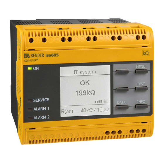
ISOMETER® isoNAV685-D
Isolationsüberwachungsgerät
Diese Kurzanleitung ersetzt nicht das Handbuch.
m m
1 1 0
Bestimmungsgemäße Verwendung
Das ISOMETER® isoNAV685-D überwacht den Isolationswider-
stand von ungeerdeten AC-Hauptstromkreisen (IT-Systemen) mit
Netzspannungen von AC 0...690 V und einer Frequenz von 60 Hz
im dreiphasigen Netz.
Die in AC/DC-Systemen vorhandenen gleichstromgespeisten
Komponenten haben keinen Einfluss auf das Ansprechverhalten.
Durch die separate Versorgungsspannung ist auch die Überwa-
chung eines spannungslosen Systems möglich.
Die maximal zulässige Netzableitkapazität beträgt, profilabhän-
gig, 0...150 μF.
Sicherheitshinweise
Gefahr eines elektrischen Schlages!
An den Klemmen liegt eine hohe Spannung an, die bei
direkter Berührung lebensgefährlich ist. Ist das Gerät mit
GEFAHR
den Klemmen L1/+, L2, L3/- an ein betriebsbedingt span-
nungsführendes IT-System angeschlossen, dürfen die
Klemmen KE und E nicht vom Schutzleiter (PE) getrennt
werden.
Gefahr von Sachschaden durch unsachgemäße
Installation!
Die Anlage kann Schaden nehmen, wenn Sie mehr als
VORSICHT
ein Isolationsüberwachungsgerät anschließen. Sind me-
hrere Geräte angeschlossen, funktioniert das Gerät nicht
und meldet keine Isolationsfehler. Schließen Sie in jedem
leitend verbundenen System nur ein ISOMETER® an.
Trennung vom IT-System beachten!
Bei Isolations- und Spannungsprüfungen an der Anlage
muss das Isolationsüberwachungsgerät für die Dauer
VORSICHT
der Prüfung vom IT-System getrennt sein. Andernfalls
kann das Gerät Schaden nehmen.
isoNAV685-D_D00215_01_Q_DEEN/01.2017
1 0 8 m m
Insulation monitoring device
This quickstart guide does not replace the operating manual.
IT System
230 kΩ
230 kΩ
Intended use
The ISOMETER® isoNAV685-D monitors the insulation resistance
of unearthed AC main circuits (IT systems) with input voltages of
AC 0...690 V and a frequency of 60 Hz in the three-phase net-
work.
DC components existing in AC/DC systems do not influence the
operating characteristics.
Due to the separate supply voltage, de-energised systems can
also be monitored. The maximum permissible system leakage ca-
pacitance is 0...150 μF, depending on the profile.
Safety instructions
Risk of electric shock!
The terminals carry high voltage and direct contact with
these terminals will likely result in electrocution. If the
DANGER
terminals L1/+, L2, L3/- of the device are connected to a
live IT system, the terminals E and KE must not be discon-
nected from the protective conductor (PE).
Risk of damage to property due to incorrect
installation!
There should only be one insulation monitoring device
CAUTION
per conductively connected installation. Damage to the
installation may result if several insulation monitoring
devices are connected. In addition, the device will not
function and will not report an insulation fault if more
than one insulation monitoring device is connected.
Disconnect from the IT system!
The insulation monitoring device must be disconnected
from the IT system before insulation or voltage tests at
CAUTION
the installation and must remain so for the duration of
the test. Otherwise the device may be damaged.
3x
1/4
1

Verwandte Anleitungen für Bender ISOMETER isoNAV685-D


Inhaltszusammenfassung für Bender ISOMETER isoNAV685-D
- Seite 1 Kurzanleitung/Quickstart ISOMETER® isoNAV685-D Isolationsüberwachungsgerät Insulation monitoring device Diese Kurzanleitung ersetzt nicht das Handbuch. This quickstart guide does not replace the operating manual. 1 0 8 m m 1 1 0 IT System 230 kΩ 230 kΩ Intended use Bestimmungsgemäße Verwendung Das ISOMETER®...
- Seite 2 ISOMETER® isoNAV685-D Montage Installation Beachten Sie den Mindestabstand zu benachbarten Geräten: Consider a minimum distance to adjacent devices: lateral 0 mm, seitlich 0 mm, oben 20 mm, unten 20 mm! top 20 mm, bottom 20 mm! Montage auf Hutschiene DIN rail mounting: Rasten Sie alle 3 mitgelieferten Montageclips (2 separat verpackt) Snap all 3 mounting clips delivered with the device (2 of them pa- des Geräts auf der Hutschiene unten so ein, dass ein sicherer und...
-
Seite 3: Wiring Diagram
ISOMETER® isoNAV685-D Anschluss an X1: Connection to X1: Externe Netzteile, zur Spannungsversorgung des External Power supply for powering iso685 via terminal ISOMETER®s über die Klemme X1, müssen den Störfesti- X1 must fulfil immunity and emission standards of the gkeits- und Emissionsanforderungen der geforderten required application. - Seite 4 ISOMETER® isoNAV685-D Inbetriebnahme Commissioning of the device Das Profil „Leistungskreise“ ist für die meisten IT-Systeme The profile "power circuits" is suitable for most of the IT geeignet. Eine Beschreibung der Profile finden Sie im systems. For a description of the profiles refer to the Handbuch.
- Seite 5 ISOMETER® isoNAV685-D Gerät meldet Alarm bzw. Gerätefehler Device signals alarm or device error Display zeigt Fehler und ggf. Messwert an. The display indicates an error and, where applicable, the Bei Isolationsfehler, DC-Verlagerungsspannungsfehler und measured value. Gerätefehler leuchten die zugehörigen LEDs. In the event of "ALARM 1"...
- Seite 6 ISOMETER® isoNAV685-D Technische Daten Technical data Isolationskoordination (IEC 60664-1/IEC 60664-3) Insulation co-ordination (IEC 60664-1/IEC 60664-3) Bemessungsspannung..........................1000 V Rated voltage ............................. 1000 V Überspannungskategorie (OVC)......................... III Overvoltage category (OVC) ..........................III Bemessungs-Stoßspannung (IEC 60664-1) ....................8 kV Rated impulse voltage (IEC 60664-1) ......................8 kV Bemessungsisolationsspannung (IEC 60664-1) ..................
- Seite 7 ISOMETER® isoNAV685-D isoNAV685-D_D00215_01_Q_DEEN/01.2017...
- Seite 8 Änderungen vorbehalten! Subject to change! © © Bender GmbH & Co. KG Bender GmbH & Co. KG Service Bender GmbH & Co. KG Service hotline: 0700-BenderHelp (Telephone and Fax) Postfach 1161 • 35301 Gruenberg • Germany Carl-Benz-Straße 8 •...