Herunterladen Inhalt Inhalt Diese Seite drucken

Werbung

Verfügbare Sprachen

Verfügbare Sprachen

CAPIX
Mounting Instruction
Montageanleitung
00103786/4/P-12.09
©
Copyright
Zumtobel Group 2009

Werbung

Inhaltsverzeichnis
loading

Inhaltszusammenfassung für Zumtobel capix

  • Seite 1 CAPIX Mounting Instruction Montageanleitung 00103786/4/P-12.09 © Copyright Zumtobel Group 2009...
  • Seite 2 Mounting instruction and user manual for CAPIX ...3 Safety information ......................3 Unpacking......................... 3 CAPIX in detail........................3 Mounting options....................... 3 Fixing ..........................3 Fixing options ......................... 3 Electrical connection ......................3 Replacing a pixel....................... 3 Operation .......................... 3 Cleaning..........................3 Montage- und Bedienungsanleitung CAPIX.....3...
  • Seite 3: Safety Information

    Also included are the correct number of mounting brackets for the number of pixels, either 10mm high (CAPIX CLIP L VE200 Art. no. 22162340) or 15mm high (CAPIX CLIP H VE200 Art. no. 22162341). There may also be replacement pixels (CAPIX 1W LED RGB VE5 Art.
  • Seite 4 CAPIX in detail Mounting bracket 10mm Mounting bracket 15mm CAPIX string (top view) with pixel (1), end of string (2), cable gland (3), string (cable) (4), SCU connector (5), direction marker (6) CAPIX string (side view) Replacement pixel Cable gland Leave the pixel in the ESD packaging until it is needed.
  • Seite 5: Mounting Options

    The ambient temperature range for operation is defined as –30° C to +50° C. The temperature of the ambient air or adjacent materials must not be outside this range when CAPIX is being operated. The pixels must not be cast in any materials.
  • Seite 6 Fixing on a wire rope intersection with 2x3mm ropes: 10mm bracket © 6/14 Copyright Zumtobel Group 2009 Art.Nr.: 00103786/4/P-12.09 Technical data was correct at time of going to press. We reserve the right to make technical changes without notice. Die technischen Inhalte entsprechen dem Stand bei Drucklegung. Änderungen bleiben vorbehalten.
  • Seite 7: Electrical Connection

    Electrical connection CAPIX may only be connected to the appropriate SCU (Streaming Control Unit). Make sure that the seal element (9) is on the cable about 15cm away from the SCU-connector (5). The element can be moved if necessary. The installation plan indicates which string needs to be connected to which connection on the SCU. The SCU instructions describe the connection to the SCU.
  • Seite 8: Operation

    Operation When the CAPIX system has been completely installed it can be put into operation within the permitted ambient temperature range of –30° C to +50° C by switching on the individual components. The storage temperature must be between –30°C and +70° C otherwise the mechanical stability of the materials cannot be guaranteed.
  • Seite 9: Montage- Und Bedienungsanleitung Capix

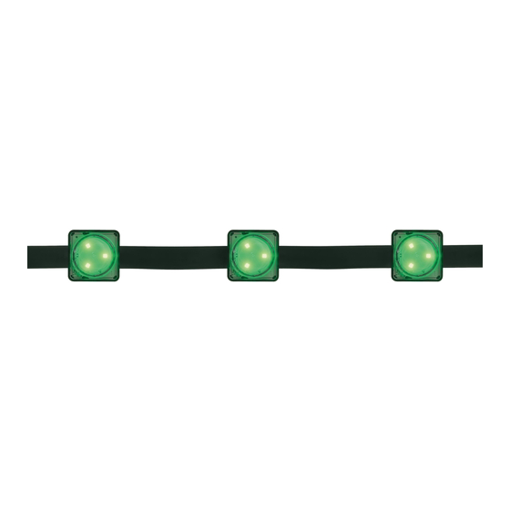
    Weiters sind der Anzahl der Pixel entsprechend viele Befestigungsfedern in der Ausführung 10mm Höhe (CAPIX CLIP L VE200 Art.-Nr. 22162340) oder 15mm Höhe (CAPIX CLIP H VE200 Art.-Nr. 22162341) beigelegt. Optional können Ersatzpixel (CAPIX 1W LED RGB VE5 Art.-Nr. 59002921) beigelegt sein.
  • Seite 10 CAPIX im Detail Befestigungsklammer 10mm Befestigungsklammer 15mm CAPIX Strang von oben mit Pixel (1), Strangende (2), Kabelverschraubung (3), Strang (Leitung) (4), SCU-Anschlussstecker (5), Richtungsmarkierung (6) CAPIX Strang von Seite Ersatzpixel Kabelverschraubung Achtung! Vor Verwendung nicht aus der ESD- Schutz-Verpackung herausnehmen damit Schäden durch elektrostatische Entladungen...
  • Seite 11 Anbausituationen Die CAPIX Pixelkette hat nach der Verbindung mit der zugehörigen SCU (Streaming Control Unit) die Schutzart IP65. Die Befestigungsfedern sind aus einer rostfreien Chrom-Nickel-Stahllegierung und reagieren somit empfindlich auf chlorhaltige Umgebungsluft. Die Verwendung innerhalb von Hallenbädern oder in der Nähe von Schwimmbädern ist nicht erlaubt.
  • Seite 12 Befestigung an Stahlseil-Kreuz mit 2x3mm Durchmesser Seilen: 10mm hohe Feder © 12/14 Copyright Zumtobel Group 2009 Art.Nr.: 00103786/4/P-12.09 Technical data was correct at time of going to press. We reserve the right to make technical changes without notice. Die technischen Inhalte entsprechen dem Stand bei Drucklegung. Änderungen bleiben vorbehalten.
  • Seite 13: Elektrischer Anschluss

    Elektrischer Anschluss CAPIX darf nur an die vorgesehene SCU (Streaming Control Unit SCU 4/50W IP65 Art.-Nr. 42178068) angeschlossen werden. Achten Sie darauf, dass das Dichtungselement (9) etwa 15cm vom SCU-Anschlußstecker (5) entfernt an der Leitung hängt. Wenn notwendig, lässt sich das Element verschieben.
  • Seite 14: Betrieb

    Betrieb Nachdem das CAPIX System komplett installiert ist, kann es durch Einschalten der einzelnen Komponenten zulässigen Umgebungstemperaturen –30° C +50°C betrieben werden. Lagertemperaturbereich darf nicht außerhalb von –30°C bis +70° C liegen, da sonst die mechanische Stabilität der Materialien nicht gewährleistet ist.

Inhaltsverzeichnis