Ripmax Wot4 Pro Bauanleitung

Verwandte Anleitungen für Ripmax Wot4 Pro


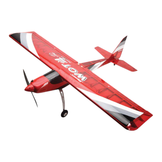
Inhaltszusammenfassung für Ripmax Wot4 Pro
- Seite 1 A-CF002PRO...
- Seite 2 Ripmax shall not be liable for any loss, consequential loss, damage will increase the risk of injury. Always keep yourself at a or expense arising from the improper use or operation in anyway.
-
Seite 3: Wichtige Hinweise
Achten Sie ebenfalls darauf, dass keine sonstigen Gegenstände Haftungsausschluss: mit sich drehenden Teilen in Berührung kommen! Denken Sie Ripmax Produkte sind häufig nur ein Teil einer ganzen auch an Ihre Haustiere! Funktionskette. Diese Funktionskette, wie auch die Einhaltung der Fliegen Sie grundsätzlich, ob mit Modellflugzeugen-, Montage und Betriebsanleitung als auch die Bedingungen und Hubschraubern- oder Multicoptern, nie in Augenhöhe... - Seite 4 Wot4 Pro Instructions/Anleitung Chris Foss The Designer / Der Designer The fascination of flight captured Chris's imagination early on in his life when he started building, from kits and plans, simple free flight gliders and rubber powered models. By his early teens, Chris was already...
-
Seite 5: Introduction / Einführung
Introduction / Einführung Congratulations on your purchase of the Wot4 Pro ARTF! Supplied with a dedicated Irvine .39 the Pro is arguably the best Wot4 ever produced thanks to the lightweight structure and increased control surfaces. Take care to read these instructions through carefully before you start your build to familiarise yourself with the build process. - Seite 6 Wot4 Pro Instructions/Anleitung Stage 1 / Schritt 1 The wings and ailerons are supplied with the hinges loose fitted, ready for installation. Remove both ailerons and insure that the hinges are inserted mid-way in their slots. Using thin cyano, pour a drop onto each hinge – above and below – ensuring the glue soaks into the hinge and surrounding wood on both ailerons.
- Seite 7 Wot4 Pro Instructions/Anleitung Stage 5 / Schritt 5 Carefully pull the lead through to the centre of the wing using the string. Pull out the servo connector through to the hole in the bottom of the wing then retain the servo lead with a short length of tape to stop the lead pulling back into the wing.
- Seite 8 Wot4 Pro Instructions/Anleitung Stage 10 / Schritt 10 Do not overtighten the control horn mounting screws as you don’t want to crush the aileron. Turn the model over and trim off any excess thread using side cutters. Nicht die Ruderhornschrauben überdrehen - Sie möchten ja nicht das Querruder zerdrücken.
- Seite 9 Wot4 Pro Instructions/Anleitung Stage 15 / Schritt 15 Adjust the pushrods to ensure that the ailerons are centred with the servos at their neutral position. Test to ensure that both ailerons move freely across their entire throw. Note that we have fitted short lengths of fuel tube over the clevis to ensure it cannot open under flight loads.
- Seite 10 Wot4 Pro Instructions/Anleitung Stage 20 / Schritt 20 Protect the covering with masking tape, then spread sufficient epoxy over the opposite panel joiner slot, wing joiner and root rib. Bring the two panels together ensuring the epoxy fills the join.
- Seite 11 Wot4 Pro Instructions/Anleitung Stage 25 / Schritt 25 Locate the pre-bent tailwheel assembly and fit the tailwheel using the collet supplied. Nehmen Sie das vorgebogene Heckfahrwerk, und montieren das Spornrad mit dem mitgelieferten Stellring. Stage 26 / Schritt 26 Screw the tailwheel assembly in position with the tailwheel wire inline with the rear of the fuselage.
- Seite 12 Wot4 Pro Instructions/Anleitung Stage 30 / Schritt 30 Roughen the wire elevator joiner to increase the bond strength in the next step. Now loosely position the joiner at the rear of the tailplane slot. Using epoxy applied to the exposed wood, glue the tailplane into its slot.
- Seite 13 Wot4 Pro Instructions/Anleitung Stage 34 / Schritt 34 Using a sharp knife, carefully remove the film from the fuselage from just in front and behind the fin mounting slot as shown so that the fin has a completely film-free surface to bond to.
- Seite 14 Wot4 Pro Instructions/Anleitung Stage 39 / Schritt 39 Insert two hinges into the rudder, ensuring they are located mid-way in their slots. Using thin cyano, pour a couple of drops onto each hinge - above and below - ensuring the glue soaks into the hinge and the surrounding wood.
- Seite 15 Wot4 Pro Instructions/Anleitung Stage 44 / Schritt 44 Fit the rubber grommets and ferrules to your elevator, rudder and throttle servos. Install the servos in the plywood radio tray, noting the orientation of the outputs as shown. Befestigen Sie die Gummiösen und Messinghülsen an Ihren Servos für Höhen- und Seitenruder und Gas.
- Seite 16 Wot4 Pro Instructions/Anleitung Stage 49 / Schritt 49 Screw a clevis onto the threaded end of the elevator pushrod so that the rod goes through the clevis by 2mm. Slide on a tube retainer and connect the clevis to the elevator horn as shown.
- Seite 17 Wot4 Pro Instructions/Anleitung Stage 54 / Schritt 54 The engine mount supplied with the Wot4 Pro is a two part design. Offer the engine up to one of the mounts, moving the engine forwards or backwards until the front of the prop driver is exactly 100 mm in front of the rear face of the mount.
- Seite 18 Wot4 Pro Instructions/Anleitung Stage 59 / Schritt 59 Locate the throttle pushrod outer sleeve. Install the tube with a drop of cyano to secure. Finden Gasdurchführung. Befestigen Plastikröhrchen mit einem Tropfen Sekundenkleber. Stage 60 / Schritt 60 Trim off the excess length of tube inside the radio bay as shown.
- Seite 19 Wot4 Pro Instructions/Anleitung Stage 64 / Schritt 64 With the servo centred tighten the clamp screw to secure the throttle pushrod and then adjust the high end and low throttle position on your transmitter. Mit dem zentrierten Servo schrauben Sie das Gasgestänge mit der Spannschraube fest.
- Seite 20 Wot4 Pro Instructions/Anleitung Stage 69 / Schritt 69 Now bolt the silencer to the engine with the spacer between the silencer and engine as shown. Nun schrauben Sie den Schalldämpfer, mit dem Abstandshalter zwischen dem Dämpfer und Motor, am Motor fest, wie gezeigt.
- Seite 21 Wot4 Pro Instructions/Anleitung Stage 74 / Schritt 74 Now fit the recommended I/C propeller (APC 11x4" for the Irvine 39) for the engine with the spinner. Your engine installation is now complete. Nun befestigen Sie den empfohlenen Propeller (APC 11x4 für den 6.3ccm Irvine Motor) am Motor mit Spinner.
- Seite 22 Ein nicht korrekt ausbalanciertes Modell erreicht nicht die Flugleistung, die es soll. Im schlechtesten Falle wird es unstabil oder nicht fliegbar. Dadurch kann es zu Schäden am Modell, oder zu Verletzungen von Ihnen oder anderen kommen. Lassen Sie diesen Schritt nicht bei der Fertigstellung Ihres Wot4 Pro aus! Control Throws / Ruderausschläge...
- Seite 23 Pre-Flight Checks / Vorflug Checks The Wot4 Pro is not a trainer as the structure is built to give a low weight for performance flying so requires extra care. Inspect the structure before you fly and transport carefully to avoid damage. Always fly the Wot4 in a safe location at a recognised club.
- Seite 24 Adresse, oder besuchen Sie unsere Webseite unter www.ripmax.de Spare parts are available for the Wot4 Pro all Ripmax stocked model shops. In case of any difficulty, any product queries, or to locate your local Ripmax stockist, please write to the address below or visit www.ripmax.com...