Inhaltsverzeichnis
Werbung
Verfügbare Sprachen
Verfügbare Sprachen
Quicklinks
Benutzerhandbuch
Deutschland
ONLINE USV-Systeme AG
Dreimühlenstr. 4
D-80469 München
Phone +49 (0) 89 / 2423990-10
Fax
+49 (0) 89 / 2423990-20
www.online-usv.de
Manual-ZintoA_final_ger_engl_it_20090929.doc
ONLINE ZINTO A-Serie
Deutsch:
English:
Italia:
Pagina 121 - 181
Italien
ONLINE UPS-Systems S.r.l.
Via Edison 12
I-20058 Villasanta (Milano)
Phone +39 (0) 39 / 2051444
Fax
www.online-ups.com
Seite
3 -
Page
63 - 120
+39 (0) 39 / 2051435
1 / 181
62
Schweiz
ONLINE USV-Systeme AG
Eigenheimstrasse 11
CH-8304 Wallisellen (Zürich)
Phone +41 (0) 1 / 9452829
Fax
+41 (0) 1 / 9453288
www.online-usv.ch
30.09.2009, Dipl.-Ing. S. Spitzley
Werbung
Kapitel
Inhaltsverzeichnis
Fehlerbehebung

Verwandte Anleitungen für Online USV ZINTO A 800


Inhaltszusammenfassung für Online USV ZINTO A 800
- Seite 1 Seite English: Page 63 - 120 Italia: Pagina 121 - 181 Deutschland Italien Schweiz ONLINE USV-Systeme AG ONLINE UPS-Systems S.r.l. ONLINE USV-Systeme AG Dreimühlenstr. 4 Via Edison 12 Eigenheimstrasse 11 D-80469 München I-20058 Villasanta (Milano) CH-8304 Wallisellen (Zürich) Phone +49 (0) 89 / 2423990-10...
- Seite 2 2 / 181 Manual-ZintoA_final_ger_engl_it_20090929.doc 30.09.2009, Dipl.-Ing. S. Spitzley...
-
Seite 3: Inhaltsverzeichnis
8.1.1 USV Single-Tower-Installation ......... 29 8.1.2 USV plus Batteriepaket-Installation ......31 Rack-Installation............32 8.2.1 Rack-Installation ZINTO A 800 / 1000 ..... 32 8.2.2 Rack-Installation ZINTO A 1500 / 2000 ....35 8.2.3 Rack-Installation ZINTO A 1500 Batteriepaket, ZINTO A 2000 Batteriepaket........37 8.2.4 Rack-Installation ZINTO A 3000,... - Seite 4 10.2 Wartung..............45 10.2.1 Sichtkontrolle............45 10.2.2 Batteriekontrolle ............46 10.2.3 Lüfterkontrolle ............46 10.3 Batteriewechsel............47 10.3.1 Batteriewechsel ZINTO A 800, ZINTO A 1000 ............47 10.3.2 Batteriewechsel ZINTO A 1500, ZINTO A 2000 ............49 10.3.3 Batteriewechsel ZINTO A 3000, ZINTO A 3000 Batteriepaket........
-
Seite 5: Abbildungsverzeichnis
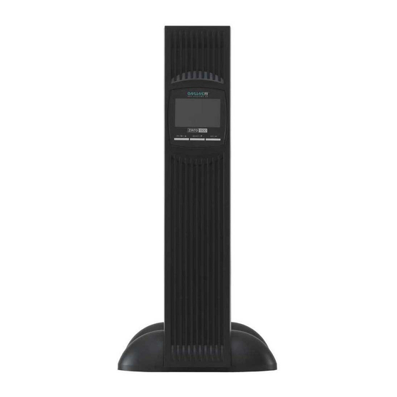
2. Abbildungsverzeichnis Abbildung 1: Vorderseite ZINTO A 800, ZINTO A 1000 Abbildung 2: Vorderseite ZINTO A 1500, ZINTO A 2000 Abbildung 3: Vorderseite ZINTO A 3000 Abbildung 4: Bedien- und Anzeigeelemente Abbildung 5: Rückseite ZINTO A 800 Abbildung 6: Rückseite ZINTO A 1000 Abbildung 7: Rückseite ZINTO A 1500, ZINTO A 2000... - Seite 6 Abbildung 21: Rack-Montage ZINTO A 800, ZINTO A 1000 - Schritt 4 Abbildung 22: Rack-Montage ZINTO A 1500, ZINTO A 2000 - Schritt 1 Abbildung 23: Rack-Montage ZINTO A 1500, ZINTO A 2000 - Schritt 2 Abbildung 24: Rack-Montage ZINTO A 1500,...
-
Seite 7: Tabellenverzeichnis
3. Tabellenverzeichnis Tabelle 1: Bedienelemente Tabelle 2: Anzeigeelemente Tabelle 3: Batteriepakete Tabelle 4: Überbrückungszeit mit zusätzlichen Batteriepaketen (BP = Batteriepaket) Tabelle 5: Kontaktbelegung DB9-Buchse Tabelle 6: Übersicht Schnittstellenzubehör Tabelle 7: Lieferumfang Tabelle 8: Anzeigelemente Tabelle 9: Warntöne Tabelle 10: Fehlersuche Tabelle 11: Abmessungen, Gewicht Tabelle 12:... -
Seite 8: Einleitung
4. Einleitung Die ONLINE USV-Systeme AG gehört zu den führenden Her- stellern von unterbrechungsfreien Stromversorgungen (USV). Seit 1988 beschäftigt sich das deutsche Unternehmen mit Entwicklung, Fertigung, Vertrieb und Support von USV- Systemen. Nach verkauften Stückzahlen sind deren Produkte die deutsche Nummer eins im USV-Markt und wegen ihrer hohen Qualität und des exzellenten Supports international... -
Seite 9: Sicherheitshinweise
5. Sicherheitshinweise VOR INSTALLATION UND INBETRIEBNAHME DAS BE- NUTZERHANDBUCH UND DIE SICHERHEITSHINWEISE AUFMERKSAM LESEN UND BEACHTEN! Transport • USV-Anlage nur in der Originalverpackung transportieren (Schutz gegen Stoß und Schlag). Aufstellung Aufgrund ihres Gewichtes werden für die Installation der USV zwei Personen benötigt. Dieses Gerät ist für die Installation in einem temperaturkontrol- lierten Raum, frei von leitfähigen Substanzen bestimmt. - Seite 10 Anschluss / Elektrische Sicherheit • Nie allein unter gefährlichen Bedingungen arbeiten. • Stellen Sie den einwandfreien Zustand der Stecker, Steck- dosen und Eingangskabel sicher. • USV-Anlage nur an einer geerdeten Schutzkontaktsteck- dose anschließen. • Maximale Stromaufnahme und ausreichende Absicherung der Hausinstallation beachten. •...
- Seite 11 • Zum völligen Abschalten der USV-Anlage für min. 3 Sek. drücken und dann das Netzkabel ziehen. • Darauf achten, dass keine Flüssigkeit oder sonstigen Fremdkörper in die USV-Anlage gelangen. Wartung, Service, Störungen • Die USV-Anlage enthält Spannungen, die gefährlich sind. Reparaturen sind grundsätzlich nur von qualifiziertem War- tungspersonal durchzuführen.
- Seite 12 • Batterien nicht öffnen oder zerstören. Freigesetztes Elekt- rolyt ist schädlich für Haut und Augen. Es kann giftig sein. • Zum Schutz vor einem Brand darf die Sicherung nur durch einen gleichen Typ mit gleichem Nennwert ersetzt werden. • USV-Anlage nicht auseinanderbauen. 12 / 181 Manual-ZintoA_final_ger_engl_it_20090929.doc 30.09.2009, Dipl.-Ing.
-
Seite 13: Produktbeschreibung
6. Produktbeschreibung Die ONLINE ZINTO A-Serie ist eine unterbrechungsfreie Stromversorgung (USV) in hochwertiger Line-Interactive- Technologie (Klassifikation VI). Sie versorgt die angeschlos- senen, sensiblen Geräte mit perfekter Sinus-Ausgangs- spannung und schützt diese hiermit vor Stromausfall und Spannungsschwankungen. Das spezielle Produktdesign bietet variable Einsatzmöglichkei- ten, je nach Kundenanforderung sowohl als Tower / Standge- rät als auch liegend im Rack. -
Seite 14: Systemkomponenten
Tank eines Kraftfahrzeuges. 6.2.1 Steuereinheit Es gibt fünf Modelle der ZINTO A-Serie: • ZINTO A 800 und ZINTO A 1000 mit interner Batterie, kei- ne Möglichkeit zur Erweiterung der Überbrückungszeit. • ZINTO A 1500 und ZINTO A 2000 Steuereinheit, jeweils ohne interne Batterie. -
Seite 15: Abbildung 2: Vorderseite Zinto A 1500, Zinto A 2000
Abbildung 2: Vorderseite ZINTO A 1500, ZINTO A 2000 Abbildung 3: Vorderseite ZINTO A 3000 6.2.1.2 Bedien - und Anzeigeelemente: Eine detaillier te Beschreibung aller Bedien- und A nzeigeele- mente ist dem Kapitel 10.5.1 zu entnehmen. Abb ildung 4: Bedien- und Anzeigeelemente 15 / 181 Manual-ZintoA_final_ger_engl_it_20090929.doc 30.09.2009, Dipl.-Ing. -
Seite 16: Tabelle 1: Bedienelemente
Bedienelemente : Taste Funktion Taste zum Ein- / Ausschalten der USV. rzu Taste für 3 Sek. gedrückt halten. Diese Taste hat 2 Funktionen: 1.) M anuelles Starten des Systemtests. TEST 2.) Deaktivierung / Reaktivierung des akusti- schen Alarms. Taste zum Starten der Konfiguration. -
Seite 17: Tabelle 2: Anzeigeelemente
Bedeutung Optische Anzeige für Sammelstö- rung, z. B. Übertemperatur, Kurz- General schluss etc. Optische Anzeige für fehlerhafte Battery Batterie bzw. entladenen Zustand. Optische Anzeige bei Überschrei- tung des Überlast-Zeit-Grenz- Overload wertes. Optische Anzeige der Ausgangs- Output spannung. Kann über Menü der 220V / 230V / 240V USV oder Software umgestellt werden. -
Seite 18: Abbildung 5: Rückseite Zinto A 800
Abbildung 5: Rückseite ZINTO A 800 Abbildung 6: Rückseite ZINTO A 1000 18 / 181 Manual-ZintoA_final_ger_engl_it_20090929.doc 30.09.2009, Dipl.-Ing. S. Spitzley... -
Seite 19: Abbildung 7: Rückseite Zinto A 1500, Zinto A 2000
Abbildung 7: Rückseite ZINTO A 1500, ZINTO A 2000 Abbildung 8: Rückseite ZINTO A 3000 19 / 181 Manual-ZintoA_final_ger_engl_it_20090929.doc 30.09.2009, Dipl.-Ing. S. Spitzley... -
Seite 20: Batteriepaket
6.2.2 Batteriepaket Für die ZINTO A-Serie sind drei verschiedene Versionen von Batteriepaketen verfügbar: Bezeichnung Beschreibung ZINTO A 1500 Batteriepaket 4 x 12V / 7,2Ah Batterie ZINTO A 2000 Batteriepaket 4 x 12V / 9Ah Batterie ZINTO A 3000 Batteriepaket 16 x 12V / 4Ah Batterie Tabelle 3: Batteriepakete .2.2.1 Batteriepaket Vorderansicht: Abbildung 9: Vorderansicht ZINTO A 1500 Batteriepaket,... -
Seite 21: Batteriepaket Rückansicht
50% / 100% Last Steuer- Modell + 1 BP + 2 BP + 3 BP + 4 BP einheit ZINTO A 800 23 / 6 ZINTO A 1000 14 / 6 ZINTO A 1500 16 / 7 40 / 16 67 / 28... -
Seite 22: Funktionsprinzip
7. Funktionsprinzip 7.1 Leistungselektronik Die USV wird an eine Schutzkontaktsteckdose angeschlossen und verbindet das öffentliche Stromversorgungsnetz mit dem an die USV angeschlossenen Verbraucher. Unter normalen Betriebsbedingungen (Normalbetrieb) wird ZINTO A mit Netzspannung aus der Steckdose versorgt. Hier- bei wird der Strom gefiltert an die angeschlossenen Verbrau- cher weitergeleitet und die Batterie überwacht. - Seite 23 unterbrechungsfreie Spannungsversorgung der an die USV angeschlossenen Verbraucher (Batteriebetrieb). ZINTO A liefert so lange Spannung bis die Batterie entladen ist. Um ein abruptes Abschalten der an die USV angeschlossenen Verbraucher als Folge einer entladenen Batterie zu verhin- dern, wurde diese mit einer Kommunikationsschnittstelle aus- gestattet.
-
Seite 24: Schnittstellenanschlüsse
7.2 Schnittstellenanschlüsse 7.2.1 Datenleitungsschutz Ein weiteres Ausstattungsmerkmal von ZINTO A ist der Daten- leitungsschutz. Spezielle Schaltkreise eliminieren Störspan- nungen bei Telefon, Modem, Fax oder Netzwerk und verhin- dern somit eine Schädigung dieser Endgeräte. Die ankommende Datenleitung wird mit der „IN“ gekennzeich- neten RJ45-Buchse auf der Rückseite der USV verbunden. -
Seite 25: Kontaktbelegung Db9-Buchse
7.2.3 Kontaktbelegung DB9-Buchse Beschreibung Batterie leer (Schließerkontakt; bei Batterie leer: Kon- takt zu Pin 5) TxD, Transmitted Data (typ. RS-232-level) RxD, Received Data (typ. RS-232-level) DTR (verbunden mit Pin 6) GND, Ground DSR (verbunden mit Pin 4) Nicht belegt Batteriebetrieb (Schließerkontakt, bei Batteriebetrieb: Kontakt zu Pin 5) Nicht belegt Tabelle 5: Kontaktbelegung DB9-Buchse... -
Seite 26: Slot Für Optionale Schnittstellenkarten
7.2.5 Slot für optionale Schnittstellenkarten Alle ZINTO A-Modelle ab 1500VA sind mit einem Steckplatz fü r optionale Schnittstellenkarten ausgestattet. Dieser ist mit den nach folgend en Produkten de r ONLINE USV-Systeme AG kompatibel: Art.-Nr. Beschreibung DW7SNMP30 Netzwerkmanagementkarte, basic DW5SNMP30 Netzwerkmanagementkarte, professionell Tabelle 6: Übersicht Schnittstellenzubehör... - Seite 27 Zur Installation der Notabschaltung bitte wie folgt vorgehen: USV-Anlage ausschalten. 2.) Lösbaren Steckverbinder aus der Klemmleiste für Not-Aus herausziehen. Hierzu zuvor die beiden äußeren Schrau- ben lösen. Die Anschlüsse des zuvor entfernten Steckverbinders mit einem pot entialfreien Schließerkontakt verbinden. (Belast- barkeit: max.
-
Seite 28: Installation
8. Installation 1.) Den Verpackungskarton und Inhalt auf etwaige Transport- schäden und Vollständigkeit überprüfen. Ist die Ware nicht frei von Schäden, bitte sofort den Spediteur informieren. Es wird empfohlen die Verpackung für künftige Verwen- dungszwecke aufzubewahren. Der Lieferumfang ist der nachfolgenden Tabelle zu ent- nehmen: Beschreibung 19“-Montagewinkel... -
Seite 29: Tower-Installation
HINWEIS: Zur Montage im Rack können wahlweise Gleit- schienen vom Schrankhersteller oder aus dem ONLINE Zubehörsortiment (Art.-Nr. Rack-Kit) verwendet werden. 2.) Die USV wird durch interne Lüfter mit forciertem Luftstrom gekühlt. Gewährleisten Sie, dass mindestens 30cm Ab- stand hinter der USV zur Verfügung stehen. 3.) Schließen Sie die USV-Anlage über ein VDE-geprüftes und CE-gekennzeichnetes Netzkabel an eine Schutzkon- taktsteckdose der Hausinstallation an. -
Seite 30: Abbildung 15: Aufstellungsvarianten Zinto A 1500
Abbildung 15: Aufstellungsvarianten ZINTO A 1500, ZINTO A 2000 Bei Betrieb mit zusätzlichen Batteriepaketen kann die USV auch mittig zu diesen positioniert werden. Für die Installation von ZINTO A 3000 sind die im Lieferum- fang enthaltenen Füße zu verwenden. Diese sind jeweils im vorderen und hinteren Drittel zu positionieren. -
Seite 31: Usv Plus Batteriepaket-Installation
8.1.2 USV plus Batteriepaket-Installation Für alle Modelle der ZINTO A-Serie ab 1500VA sind zusätz- liche Batteriepakete erhältlich. ur Installation von U SV und Batteriepaket bitte analog zu Kapitel 8.1.1 verfahren. Vor Anschluss zusätzlicher Batteriepakete sind die USV- Anlage vom Stromversorgungsnetz und die Verbraucher von USV-Anlage zu trennen. -
Seite 32: Batteriepaket Für Zinto
Schwerpunktes sowie ausreichender Frischluftzufuhr installie- ren. 8.2.1 Rack-Installation ZINTO A 800 / 1000 Zur Rack-Installation der ZINTO A 800 und ZINTO A 1 000 ist das optionale Rack-Kit (Art.-Nr. Rack-Kit-ZA800) zu verwen- den. Dies besteht im Wesentlichen aus einer Grundplatte, einem USV-Haltewinkel, Blindabdeckungen zur Adaption auf 19“-Breite und Montagematerial. -
Seite 33: Abbildung 19: Rack-Montage Zinto A 800, Zinto A 1000 - Schritt 2
Hierbei ist wie folgt vorzugehen: efestigung des USV-Haltewinkels. Abbildung 18: Rack-Montage ZINTO A 800, ZINTO A 1000 - Schritt 1 2.) Montage von USV-Anlage mit montiertem USV- Haltewinkel an der Grundplatte. Abbildung 19: Rack-Montage ZINTO A 800, ZINTO A 1000 - Schritt 2 33 / 181 Manual-ZintoA_final_ger_engl_it_20090929.doc... -
Seite 34: Abbildung 20: Rack-Montage Zinto A 800, Zinto A 1000 - Schritt 3
3.) Positionierung und Befestigung des Gesamtsystems im Rack. Abbildung 20: Rack-Montage ZINTO A 800, ZINTO A 1000 - Schritt 3 4.) Anbringung der Blindabdeckungen an beiden Seiten. Abbildung 21: Rack-Montage ZINTO A 800, ZINTO A 1000 - Schritt 4 34 / 181 Manual-ZintoA_final_ger_engl_it_20090929.doc... -
Seite 35: Rack-Installation Zinto A 1500 / 2000
8.2.2 Rack-Installation ZINTO A 1500 / 2000 ZINTO A 1500 und ZINTO A 2000 sind durch die spezielle Gehäuseform so konstruiert, dass in Rack-Installation beide Komponenten (Steuereinheit und Batteriepaket) nebeneinan- der angeordnet werden. Um größtmögliche Stabilität zu ge- währleisten, müssen beide Komponenten miteinander verbun- den werden. -
Seite 36: Zinto A 2000 - Schritt 3
4.) Zur Verbindung beider Komponenten den Montagerahme (breite Version) mit den beiliegenden Schrauben an de offenen Front beider Gehäuse fixieren. Die Rac k-Befesti- gungslöcher stehen hierbei seitlich über. Abbildung 24: Rack-Montage ZINTO A 1500, ZINTO A 2000 - Schritt 3 5.) Die Frontblenden können jetzt wieder angebracht werden. -
Seite 37: Rack-Installation Zinto A 1500 Batteriepaket, Zinto A 2000 Batteriepaket
Ab ldung 26: Rack-Montage ZINTO A 1500, ZINTO A 2000 - Schritt 5 8.2.3 Rack-Installation ZINTO A 1500 Batterie- paket, ZINTO A 2000 Batteriepaket Bei Verwendung mehrerer B atteriepakete für ZINTO A 1500 oder ZINTO A 2000 in 19“-M ontage müssen jeweils zwei der Batteriepakete analog dem Kapitel 8.2.2 zusammengefügt werden. -
Seite 38: Betrieb
9. Betrieb 1.) Zum ordnungsgemäßen Betrieb muss die Batterie voll- ständig geladen sein. Die Ladezeit ist dem Kapitel 11.2 zu entnehmen. Die USV-Anlage kann auch unmittelbar ohne Laden eingesetzt werden, doch kann dann die Überbrü- ckungszeit kürzer als der angegebene Nennwert sein. 2.) Vor dem Betrieb muss siche gestellt werden, dass Ausgangsspannung der USV-Anlage mit der Eingang- spannung des angeschlossenen Computers überein-... - Seite 39 Die angeschlossenen Verbra ucher werden mit gefilterter Netz- spannung versorgt. Zusätzlich wird diese durch die Buck- & Boost-Regeleinheit stabilisiert und überwacht. In diesem Betriebszustand leuchtet Line in Kombination mit vorgestellter Auslastungsanzeige ( ) sowie eine der LEDs für gewählte Eingangssensitivität und Ausgangsspannung. 2.) Batteriebetrieb: Verlässt die Eingangsspannung im Normalbetrieb die definier- te Spannungs- und / oder Frequenztoleranz, bzw.
-
Seite 40: Einschalten
Nach einem manuellen Shutdown von ZINTO A muss die USV-Anlage wieder von Hand gestartet werden. Die Batterie wird im Normalbetrieb wieder geladen. Die Lade- zeit variiert u nd ist dem Kapitel 11.2 zu entnehmen. 9.2 Einschalten Es gibt zwei Möglichkeiten die USV einzuschalten: 9.2.1 Normaler Start (Ein gangsspannung vorhanden) -
Seite 41: Ausschalten
drückt werden bis zum Erlöschen des akustischen Signales (ca. 3 Sek.). Jetzt schaltet der Wechselrichter ein und die USV arbeitet in der Betriebsart Batteriebetrieb. Die Betriebsart Batteriebetrieb wird durch gleichzeitiges euchten von Battery sowie einer Status-LED der Menüs Input und Output bei g leichzeitigem Ertönen eines akusti- schen Sign... -
Seite 42: Überlast
4 Überlast i Geräteüberlast (Last >110%) ertönt ein akustischer, perio- cher Signalton und leuchtet O verload. Die Versorgung der geschlossenen Verbraucher bleibt erhalten, jedoch muss die angeschl ossene Las t umgehend reduziert werden. Die Nichtbe achtung des Gerätezustandes „Überlast“ kann ein Abschalten der USV-Anlage zur F olge haben! Zu vermeiden... - Seite 43 nommen. Der Wechselrichter versorgt die ges amte Last mit Strom aus der Batterie, sodass die gesamte Prozesskette getestet wird. Nach Abschluss der Testrou tine wird automa- tisch auf Normalbetrieb zurückgeschaltet. Starten der Systemdiag nose: • TEST drücken bis der akustische Dauer-Signalton er- lischt (ca.
- Seite 44 DataWatch-Software: Weiterhin besteht die Möglichkeit den Batterietest ferngesteu- ert über die DataWatch-Software zu aktivieren. Nähere Infor- ationen hierzu sind der separaten Bedienungsanleitung auf er DataWatch-CD zu entnehmen. 44 / 181 Manual-ZintoA_final_ger_engl_it_20090929.doc 30.09.2009, Dipl.-Ing. S. Spitzley...
-
Seite 45: Wartung, Anzeigen, Problembehebung
10. Wartung, Anzeigen, Problembehebung 10.1 Lagerung ei Lagerung in gemäßigten Klimazonen sollten die Batterien alle drei Monate für 1-2 Stunden geladen werde n. In Umge- bungen mit höheren Temperaturen sollten die L adeintervalle auf zwei Monate verkürzt we rden. .2 Wartung Die ZINTO A-Serie benötigt nur einen sehr geringen Aufwand Wartung. -
Seite 46: Batteriekontrolle
Ist die USV sehr stark verstaubt, sollte sie vorsorglich gereinigt werden um einen optimalen Wärmeaustausch zu gewährleis- ten. 10.2.2 Batteriekontrolle Die Batterie ist die Schlüsselkomponente des USV-Systems. Die Lebenserwartung der Batterie ist beschränkt und maßgeb- lich abhängig von der Umgebungstemperatur und Anzahl der Lade- / Entladezyklen. -
Seite 47: Batteriewechsel
.) Die zwei seitlichen Schrauben lösen. Danach vorsichtig die Kunststoffblende vom Gerät ziehen. Achtung: Blende dabei nicht zu sehr verkanten. Abbildung 27: Batteriewechsel ZINTO A 800, ZINTO A 1000 - Schritt 1 2.) Batterie-Steckverbinder des Batteriesystems lösen. Da- nach Halteblech nach rechts schieben und herausneh- men. -
Seite 48: Zinto A 1000 - Schritt 2
Abbildung 28: Batteriewechsel ZINTO A 800, ZINTO A 1000 - Schritt 2 3.) Die neuen Batterieblöcke der Verpackung entnehmen, gemäß d er ursprünglich in der USV eingesetzten Batterie positioni eren, miteinander fixieren und elektrische Verbin- dung zwischen den Blöcken herstellen. -
Seite 49: Batteriewechsel Zinto A 1500
10.3.2 Batteriewechsel ZINTO A 1 500, ZINTO A 2000 1.) Die untere Schraube lösen und danach vorsichtig die ststoffblende des Batteriemoduls abziehen. Abbildung 29: Batteriewechsel ZINTO A 1500, ZINTO A 2000 - Schritt 1 2.) Batterie-Steckverbinder trennen und Halteblech durch seitliches Verschieben nach rechts entfernen. -
Seite 50: Batteriewechsel Zinto A 3000
10.3.3 Batteriewechsel ZINTO A 300 0, ZINTO A 3000 Batteriepaket 1.) Das Batteriefach d er ZINTO A 3000 durch vorsichtiges Ziehen der Kunststoffblende an beiden Enden öffnen. Abbildung 31: Batteriewechsel ZINTO A 3000, ZINTO A 3000 Batteriepaket - Schritt 1 2.) Den Batteri e-Steckverbinder lösen und das Halteblech entfernen. -
Seite 51: Funktionsüberprüfung
4.) Anschließe nd die neu en Batterieblöcke der Verpackung entnehmen , gemäß der ursprünglich in der USV einge- setzten Ba tterien positionieren, miteinander fixieren und elektrische Verbindung zwischen den Blöcken herstellen. Alternativ or iginal ONLINE Ersatzbatterie verwenden. 5.) Neue Batte rieeinheiten vorsichtig in den Schacht der USV- Anlage set zen und bis zum Anschlag langsam hinein-... -
Seite 52: Anzeigen Und Warntöne
0.5 An eigen und Warntöne 10.5.1 An zeige Ein- bzw . Ausschalten r USV-Anlage durch ca. 3 S ekunde n langes D rücken der Taste – mindestens bis zum Erl öschen des akus sche ignals. Taste z ur manuellen E leitung der System- TEST diagnose / des Batterietes iehe a... - Seite 53 Schritt 2: Nach A uswahl und Be stätigung der Aus gangssp annung w in de n Men üpunkt Input gewech selt. Durch wiede holtes Drücken von für di e Dauer von eine ekunde kann zwi- schen angegeben Betriebsarten gewählt werden. Zur Über nahme einer Aus- wahl für 3 Sekunden drücken.
-
Seite 54: Warntöne
LED-Anzeige für fehlerhaften Wechselrichter. Inverter LED-Anzeige von Sammelstörung, z. B. Über- General lastung oder sekundärer K urzschluss. LED-Anzeige für St örung in der Batterie, Batte- ry-LED blinkt alle 2 Sekunden. Ursache könnte ein fehlerhafter Kontakt oder eine alterungs- Battery bedingt zu schwache Batterie sein. Kontakt überprüfen! Wenn hier keine Abhilfe, neue Bat- terie instal lieren. -
Seite 55: Tabelle 10: Fehlersuche
Problem Ursache Lösung Gebäudesteckdose te Elektriker kontak- fehlerhaft. tieren. Kurzschluss im 1. Alle Verbrauche r von USV-Ausgang oder r USV entfernen. Überlast. V neu starten und Verbraucher nachein- ander r mit der V ve rbind 2. Si chers tellen , dass Verb rauc her ni... - Seite 56 Bei Anruf der Hotline unbedingt nac hfolgende Informati onen bereithalten: • Modell- und Seriennummer • Kauf- und Insta llationsdatum • Ausführliche Beschreibu ng des Pro blems Die Hotline bietet koste nlose te chnische Unterstützung und entscheidet nach Sc hilderu ng de s Problems über d as w eite...
-
Seite 57: Technische Daten
11. Technische Daten 11.1 Abmessungen, Gewic t MODELL Abmessungen USV, 86 x 235 x 86 x 383 217 x 87 x 414 B x H x T (mm) Abmessungen Batterie- 86 x 217 x 87 x 4 paket, B x H x T (mm) Gewicht USV (kg) 31,5 Gewicht Batteriepaket... - Seite 58 Generator-Modus (V) 230 (176 – 288, +/-4%) Wide-Range-Modus (V) 230 (154 – 288, +/-4%) Frequenz (Hz) 50 / 60 +/- 10% Normal-Modus (Hz) 45 / 55 +/-0,1 bzw. 55 / 65 +/-0,1 Generator-Modus (Hz) 40 / 55 +/-0,1 bzw. 40 / 65 +/-0,1 Wide-Range-Modus (Hz) 45 / 55 +/-0,1 bzw.
-
Seite 59: Tabelle 12: Elektrische Spezifikationen
BATTERIE CSB / CSB / Yuasa / CSB / CSB / NP7,2- 1234W 1234W 1272 1221W (F2) (F2) 12V / 12V / 12V / 12V / 12V / 7,2Ah 7,2Ah Anzahl Lebensdauer 3 – 5 Jahre gemäß EUROBAT Ladezeit auf 90% Kapazität Ladestromstärke (A) Batterietest Automatisch, manuell, ferngesteuert... -
Seite 60: Umgebungsbedingungen
11.3 Umgebungsbedingungen MODELL Betriebstemperatur (°C) 0 – 40 Lagertemperatur (°C) 0 bis +25 Relative Luftfeuchtigkeit (%) 20 – 80, nicht kondensierend Kühlung aktive Kühlung <1500m, Einsatzhöhe Leistungsminderung von 1% je weitere 100m Betriebsgeräusch (dBA) <45 <45 <50 <50 <55 Tabelle 13: Umgebungsbedingungen 11.4 Zertifizierungen MODELL Sicherheit... -
Seite 61: Garantie
Nutzung eines Gerätes, Verlust von Software oder Daten, Ersatzkosten, Ansprüche von Dritten oder andere Kosten. Der Inhalt unterliegt dem Urheberrecht Copyright © 2007 der ONLINE USV- Systeme AG. Alle Rechte vorbehalten. Vervielfältigung im Ganzen oder in Teilen ist ohne Erlaubnis nicht gestatte 61 / 181 Manual-ZintoA_final_ger_engl_it_20090929.doc... - Seite 62 62 / 181 Manual-ZintoA_final_ger_engl_it_20090929.doc 30/09/2009, Dipl.-Ing. S. Spitzley...
- Seite 63 User Manual ONLINE ZINTO A series Germany Italy Switzerland ONLINE US V-Systeme AG ONLINE UPS-Systems S.r.l. ONLINE U SV-Systeme AG Promenadeplatz 12 Via Edison 12 Eigenheimstrasse 11 D-80333 M unich I-20058 Villasanta (Milano) CH-8304 Wallisellen ( Zürich) Phone +49 (0) 89 / 2423990-10 Phone +39 (0) 39 / 2051444 Phone +41 (0) 1 / 945 2829...
- Seite 64 64 / 181 Manual-ZintoA_final_ger_engl_it_20090929.doc 30/09/2009, Dipl.-Ing. S. Spitzley...
-
Seite 65: Conte Nts
8.1.2 Ins llation of UPS plus Batterypack......92 Rack installation ............93 8.2.1 Rack installation ZINTO A 800 / 1000...... 8.2.2 Rack installation ZINTO A 1500 / 2000....96 8.2.3 Rack installation ZINTO A 1500 Batterypack, ZINTO A 2000 Batterypack.... - Seite 66 10.2.2 Battery inspection........... 106 10.2.3 Fan inspection............106 10.3 Battery replacement..........106 10.3.1 Batte ry replacement ZINTO A 800, ZINTO A 1000 ............107 10.3.2 Battery replacement ZINTO A 1500, ZINT O A 2000 ............109 10.3.3 Battery replacement ZINTO A 3000, ZINT O A 3000 Batterypack........
-
Seite 67: List Of Figures
2. List of figures Figure 1: Front of ZINTO A 800, ZINTO A 1000 Figure 2: Front of ZINTO A 1500, ZINTO A 2000 Figure 3: Front of ZINTO A 3000 Figure 4: Controls and indicators Figure 5: Rear of ZINTO A 800... - Seite 68 Figure 21: Rack mounting ZINTO A 800, ZINTO A 1000 - step 4 Figure 22: Rack mounting ZINTO A 1500, ZINTO A 2000 - step 1 Figure 23: Rack mounting ZINTO A 1500, ZINTO A 2000 - step 2 Figure 24:...
-
Seite 69: List Of Tables
3. List of tables Table 1: Controls Table 2: Indicators able 3: Batterypacks Table 4: Power backup time with additional Batterypacks (BP = Batterypack) ble 5: Pin assignments DB9 socket able 6: Overview, interface accessories Table 7: Items supplied Table 8: Indications Table Acoustic warnings... -
Seite 70: Introduction
4. Introduction ONLI NE USV-Systeme AG is a leading manufacturer of unin- terruptible power supplies (UPS). The German company has en involved in the development, manufacture, marketing and support of UPS systems since 1988. On the UPS market in Germany the company's products are number one based on mber of units sold, and are respecte d internationally due to their high quality and the excellent support. -
Seite 71: Safety Instructions
5. Safety instructions BEFORE INSTALLING THE DEVICE AND STARTING IT UP, READ CAREFULLY AND OBSERVE THE USER MANUAL D SAFETY INSTRU CTIONS! nsport • Please only transport the UPS system in the original pack- aging (to protect against shock and impact). Set-up e to its weight, the UPS needs to be installed by two peo- is device is intended to be installed in a tempera... - Seite 72 Connection / electrical safety • Never work alone in dangerous conditions. • Always ensure that plugs, wall sockets and input cables are in good working order. • Connect the UPS system only to an earthed wall socket with earth contact. •...
- Seite 73 • Ensure that no liquid or other foreig n bodies enter the UPS system. Maintenance, servicing, faults • The UPS system operates with hazardous voltages. Re- pairs may only be carried out by qualified maintenance personnel. • Attention! Risk of electric shock. Even after the unit is dis- connected from the mains power supply (wall socket), components inside th e UPS system are still connected to...
-
Seite 74: Product Description
6. Product description The ONLINE ZINT O A series is an uninterru ptible power sup- ly (UPS) in high quality line interactive technology (classifica- on VI). It supplies the sensitive devices connected with per- fect sinusoidal output voltage and pr otects them against power failure and voltage fluctuations. -
Seite 75: System Components
All the UPS models have identical control and indicator pan- els. The buttons are the co ntrols, the light emitting diodes the indicators. Figure 1: Front of ZINTO A 800, ZINTO A 1000 75 / 181 Manual-ZintoA_final_ger_engl_it_20090929.doc 30/09/2009, Dipl.-Ing. S. Spitzley... -
Seite 76: Figure 2: Front Of Zinto A 1500, Zinto A 2000
Figure 2: Front of Z INTO A 1500, ZINTO A 2000 Figure 3: F ront of ZINTO A 3000 6.2.1.2 Controls and indicators: You will find a detailed des cription of all controls and indicators in section 10.5.1. Figure 4: Controls and indicators 76 / 181 Manual-ZintoA_final_ger_engl_it_20090929.doc 30/09/2009, Dipl.-Ing. -
Seite 77: Table 1: Controls
Controls: Button Function Button for switching on and off the UPS. Keep button pressed for 3 sec. This button has 2 functions: 3.) Manual starting of the system test. TEST 4.) Deactivation / reactivation of the acoustic alarm. Button for starting configuration. Configura- Set I/O tion refers to the programming of the input sensitivity and output voltage. -
Seite 78: Table 2: Indicators
Significance Optical indication of a general malfunction, e.g. overtemperature, General short circuit, etc. Optical indication of a faulty bat- Battery tery or a discharged battery. Optical indication that the overload Overload time limit has been exceeded. Optical indication of the output Output voltage. -
Seite 79: Figure 5: Rea R Of Zinto A 800
Figure 5: Rea r of ZINTO A 800 Figure 6: Rear of ZINTO A 1000 79 / 181 Manual-ZintoA_final_ger_engl_it_20090929.doc 30.09.2009, Dipl.-Ing. S. Spitzley... -
Seite 80: Figure 7: Rear Of Zinto A 1500, Zinto A 2000
Figure 7: Rear of ZINTO A 1500, ZINTO A 2000 Figure 8: Rear of ZINTO A 3000 80 / 181 Manual-ZintoA_final_ger_engl_it_20090929.doc 30.09.2009, Dipl.-Ing. S. Spitzley... -
Seite 81: Batterypack
6.2.2 Batterypack Thre e versi ons of batterypack are available for the ZINTO A series: Designation Description ZINTO A 1500 Batterypack 4 x 12V / 7,2Ah battery ZINTO A 2000 Batterypack 4 x 12V / 9Ah battery ZINTO A 3000 Batterypack 16 x 12V / 4Ah battery Table 3: Batterypacks 6.2.2.1 Front view of Batterypack:... -
Seite 82: Figure 11: Rear View Of Zinto A 1500 Batterypack
50% / 100% load Control Model + 1 BP + 2 BP + 3 BP + 4 BP unit ZINTO A 800 23 / 6 ZINTO A 1000 14 / 6 ZINTO A 1500 16 / 7 40 / 16 67 / 28... -
Seite 83: Principle Of Operation
7. Principle of operation 7.1 Power electronics The UPS is connected to a wall socket with earth contact and connects the mains to the loads connected to the UPS. Under normal ope rating conditions (normal mode), the ZINTO is supplied with mains voltage from the wall socket. During this process the power provided to the connected loads is filtered and the battery monitore... - Seite 84 loads connected to the UPS as a consequence of a dis- harged battery, the UPS has been equipped with a communi- cation inte rface. The loads connected can be monitored and controlled using this interface. The power backup time pro- vided by the batte ry is essentially dependent on the loads connected.
-
Seite 85: Interface Connections
7.2 Interface connections 7.2.1 Data line protection A further feature of the ZINTO A is the data line protection. Special circuits eliminate interference on a telephone, modem, fax or network and in this way prevent damage to the equip- ent. The incoming data line is conne cted to the RJ45 socket on the... -
Seite 86: Pin Assignments Db9 Socket
7.2.3 Pin assignments DB9 socket Description Battery discharged (normally open contact; if battery discharged: contact to pin 5) TxD, Transmitted Data (typical RS-232 level) RxD, Received Data (typical RS-232 level) DTR (connected to pin 6) GND, ground DSR (connected to pin 4) Not used Battery mode (normally open contact, in batt ery mode:... -
Seite 87: Slot For Optional Interface Cards
.5 Slot for opti onal interface cards All ZINTO A models from 1500VA are equipped with a slot for opti onal interface cards. This slot is compatible with the follow- ONLINE USV-Systeme AG products: Art. No. Description DW7SNMP30 Network management card, basic... - Seite 88 To install the emergency power off, please proceed as follows: 1.) Switch off UPS system. 2.) Remove connector from the emergency power off terminal block. For this purpose first undo the two outer screws. 3.) Connect the connections on the connector removed to a floating normally open contact.
-
Seite 89: Installa On
8. Installation 1.) Check the box and contents for any transport damage and for completeness. If the goods are damaged, please in- form the freight carrier immediately. It is reco mmended to keep the packaging for possible future use. The items supplied are given in the following table: Description 19“... -
Seite 90: Tower Installation
ZINTO A series can be used both vertically as a tower and horizontally in a rack. ZINTO A 800, ZINTO A 1000 and ZINTO A 3000 comprise only one component in the basic configuration. For ZINTO A 1500 and ZINTO A 2000 two... -
Seite 91: Figure 15: Installation Variants For Zinto A 1500
Figure 15: Installation variants for ZINTO A 1500, ZINTO A 2000 In case of operation with additional batterypacks, the UPS can also be positioned in the middle between the packs. The feet included in the items supplied are to be used for the stallation of the ZINTO A 3000. -
Seite 92: Installation Of Ups Plus Batterypack
8.1.2 Installation of UPS plus Batterypack Additional batterypacks are available for all models in the ZINTO A series from 1500VA. To install the UPS and batterypack, please proceed as de- scribed in section 8.1.1. Prior to the connection of additional batterypacks, the UPS system is to be isolated from the mains and the loads are to be isolated from the UPS system. -
Seite 93: Rack Installation
.2.1 Rack installation ZINTO A 800 / 1000 The optional rack kit (art. no. Rack-Kit-ZA800) is to be used for rack installation of the ZINTO A 800 and ZINTO A 1000. This kit essentially comprises a base plate, a UPS bracket, blanking panels for adaptation to a width of 19“... -
Seite 94: Figure 18: Rack Mounting Zinto A 800, Zinto A 1000 - Step 1
Proceed as follows: 1.) Fasten th e UPS bracket. Figure 18: Rack mounting ZINTO A 800, ZINTO A 1000 - step 1 2.) Mount the UPS system with UPS bracket fitted on the base plate. Figure 19: Rack mounting ZINTO A 800, ZINTO A 1000 - step 2 94 / 181 Manual-ZintoA_final_ger_engl_it_20090929.doc... -
Seite 95: Figure 20: Rack Mounting Zinto A 800, Zinto A 1000 - Step 3
3.) Position and fasten the complete system in the rack. Figure 20: Rack mounting ZINTO A 800, ZINTO A 1000 - step 3 4.) Attach the blanking plates on both sides. Figure 21: Rack mounting ZINTO A 800, ZINTO A 1000 - step 4 95 / 181 Manual-ZintoA_final_ger_engl_it_20090929.doc... -
Seite 96: Rack Installation Zinto A 1500 / 2000
8.2.2 Rack installation ZINTO A 1500 / 2000 The special housing shape of ZINTO A 1500 and ZINTO A 2000 is designed such that the two components (control unit and batterypack) can be arranged side by side in the rack installation. - Seite 97 the screws included. The rack fastening holes protrude at the sides. Figure 24: Rack mounting ZINTO A 1500, ZINTO A 2000 - step 3 5.) The front panels can now be re-fitted. Figure 25: Rack mounting ZIN TO A 1500, ZINTO A 2000 - step 4 6.) T ond mounting frame (narrow version) is now fixed to the r...
-
Seite 98: Rack Installation Zinto A 1500 Batterypack
Figure 2 6: Rack mounting Z INTO A 1500, ZINTO A 2000 - step 5 8.2.3 Rack installation ZINTO A 1500 Battery- pack, ZINTO A 2 000 Batterypack On the use of several batterypacks for ZINTO A 1500 INTO A 2000 installed in a 19“ rack, two batterypacks must e joined together as described in section 8.2.2. -
Seite 99: Operat N
9. Operation 1.) The battery must be fully charged for correct operation. You will find the charging time in section 11.2. The UPS system can also be used immediately without charging, however in this case the power backup time may be shorter than the nominal value stated. - Seite 100 e loads connected are supplied with filtered mains voltage. addition, the mai ns voltage is stabilised and monitored by e Buck & Boost regulator unit. In this opera ting stat e, Line is illuminated in combination with the utilisatio n indicator ( ) as well as one of the LEDs for the selected inp ut sensitivity and outp ut voltage.
-
Seite 101: Sw Hing On
The battery is recharged in the normal mode. The chargi time varies, it is given in section 11.2. 9.2 Switching There are two ways of switching on the UPS: 9.2.1 Normal start (input voltage present) After connection to an earthed wall socket, press until the coustic signal stops (approx. -
Seite 102: Sw Hing Off
Output menus and an acoustic signal (1 x every 4 seconds). In addition, the scale provides information on the accumu- lator capacity. ATTENTION: There may still be a voltage on the output sockets of the UPS system even if the mains supply has been switched off or the mains cable has b disconnected. -
Seite 103: System Diagnostics / Battery Test
Ignoring the "Overload" device state can result in th e shut- down of the UPS system! Brief device overloads as caused by laser printers or laser fax m achines are also to be avoided. Also, do not connect any household appliances such as hair- drie rs, vacuum cleaners or the like to the UPS system. - Seite 104 is inactive, it can be reactivated by pressing TEST again for one second. NOTE: The acoustic alarm cannot be switched off in the following situations: battery low, overload, fan failure / fault, time shut- down, overtemperature. If a fault is found during the system diagnostics given above, process is interrupted immediately and the loads con- ected switched to the normal mode without delay.
-
Seite 105: Maintenance, Indications, Trouble Shooting
10. Maintenance, indications, trouble shooting 10.1 Storage f th e batteries are stored in temperate c limatic zones, they hould be charged every three months for 1-2 hours. You should shorten the charging intervals to two months in loca- tions with higher temperatures. 10.2 Maintenance The ZINTO A series only requires very little maintenance. -
Seite 106: Battery Inspection
2.2 Battery inspection The battery is the key component of the UPS system. The battery has a limited expected service life, which is heavily dependent on the ambient temperature and the number of charging/discharging cycles. High ambient temperatures and p discharging will considerably shorten the expected ser- vice life. -
Seite 107: Batte Ry Replacement Zinto A
Do not tilt the pane l too much during this process. Figure 27: Bat ry replacement ZINTO A 800, ZINTO A 1000 - step 1 2.) Disconnect battery connector for the battery system. Then push retain ing plate to the right and remove. The battery is... - Seite 108 Figure 28: Batter replacement ZIN TO A 800, ZINTO A 1000 - step 2 Remove the new battery blocks from the packaging, posi- tion as the batteries originally fitted in the UPS, fasten together a nd make electrical connection between the blocks.
-
Seite 109: Battery Replacement Zinto A 1500
10 .2 Battery re lacement ZIN O A 1500, ZINTO A 2000 do the bott om sc rew and the n care fully remove the stic panel on the battery m ule. Figure 29: Battery replacement ZINTO A 1500, ZINTO A 2000 - step 1 .) Di connect ba ttery connecto... -
Seite 110: Battery Replacement Zinto A 3000
10 .3 Battery lacemen t ZINT O A 3000, ZINT O A 30 00 Batterypa k ) O en the batte rypa ck for the ZIN TO A 3000 by carefully pulling the plastic panel at both ends. Figure 31: Battery replacement ZINTO A 3000, ZINTO A 3000 Batterypack - step 1 2.) Disconnect the battery co nnector and remove the retaining... -
Seite 111: Function Check
Then remove the ne w battery blocks from the packaging, position as per th e ba tteri es originally fitted in the UPS, fasten together and make electrical connection between the blocks. Alternatively, use genuine ONLINE replacement bat- tery. 5.) Carefully fit new battery units in the slot in the UPS system and push in slowly to the stop. -
Seite 112: Ind Ations And Acoustic Warnings
10.5 Indications and acousti arnings 10.5.1 Indications Switch on and off the UPS system by pres the button for a prox. 3 second – at until the acoustic signal stops. Button for manually initiating the system diag- TEST nostics / the battery test. See also section 9.5. - Seite 113 Step 2: After the se ction and accepta nce o the output voltage, the Input menu command is opened. By pressing again for one second you can select between th e op erating modes given. To accept a selection, press for 3 seconds.
-
Seite 114: Acoustic Wa Rnings
LED indicato r for battery fault, Battery LED flashes every 2 seconds. The cause could be a faulty contact or a battery that is no longer Battery adequate d to a ng. Check c acts! this check d rectify the probl , inst new battery. -
Seite 115: Table 10: Troubleshooting
Problem Cause Solution Mains wall socket Please contact electri- faulty. cian. Short circuit in the 3. Remove all loads UPS output or from the UPS. overload. Re-start UPS and re-connect loads to the UPS one after the other. 4. Ensure the loads are not faulty (internal short circuit). -
Seite 116: Technical Data
11. Technical da 11.1 Dimensions, we ight MODEL 438 x UPS dimensions, 86 x 235 x 86 x 3 217 x 87 x 414 W x H x D (mm) 438 x Batterypack dimensions, 86 x 217 x 87 x 414 W x H x D (mm) UPS weight (kg) 31.5... - Seite 117 Generator mode (V) 230 (176 – 288, +/-4%) Wide Range mode (V) 230 (154 – 288, +/-4%) Frequency (Hz) 50 / 60 +/- 10% Normal mode (Hz) 45 / 55 +/-0.1 or 55 / 65 +/-0.1 Generator mode (Hz) 40 / 55 +/-0.1 or 40 / 65 +/-0.1 Wide Range mode (Hz) 45 / 55 +/-0.1 or 55 / 65 +/-0.1 Current, max.
-
Seite 118: Table 12: Electrical Specifications
BATTERY CSB / CSB / Yuasa / CSB / CSB / NP7.2- 1234W 1234W 1272 1221W (F2) (F2) 12V / 12V / 12V / 12V / 12V / 7.2Ah 7.2Ah Quantity Service life 3– 5 years in accordance with EUROBAT Charging time to 90% ca- pacity Charging current (A) -
Seite 119: Ambient Conditions
11.3 Ambient conditions MODEL Operating temperature (°C) 0 – 40 Storage temperature (°C) 0 to +25 Relative humidity (%) 20 – 80, non-condensing Cooling Active cooling <1500m, Altitude Power reduction of 1% per additional 100m Operating noise (dBA) <45 <45 <50 <50 <55... -
Seite 120: Warranty
12. Warranty ONLINE USV steme AG (ONLINE) warrants that this product will be free of defects in materi als and workmanship for a period of two years from the date of purchase. extent of ONLINE’s liability under the terms of this warranty... - Seite 121 Manuale dell'Uten rie ONLINE ZINTO A Germania Italia Svizzera ONLINE USV-Systeme AG ONLINE UPS-Systems S.r.l. ONLINE USV-Systeme AG Promenadeplatz 12 Via Edison 12 Eigenheimstrasse 11 D-80333 München I-20058 Villasanta (Milano) CH-8304 Wallisellen (Zürich) Tel. +49 (0) 89 / 2423990-10 Tel. +39 039 / 2051444 Tel.
- Seite 122 122 / 181 Manual-ZintoA_final_ger_engl_it_20090929.doc 30.09.2009, Dipl.-Ing. S. Spitzley...
-
Seite 123: Sommario
8.1.2 In stallazione di UPS e pacco batterie ....151 Installazione in rack ..........152 8.2.1 I nstallazione in rack ZINTO A 800 / 1000 ....152 8.2.2 I nstallazione in rack ZINTO A 1500 / 2000 .... 155 8.2.3 nstallazione in rack pacco batterie INTO A 1500 e pacco batterie ZINTO A 2000 .. - Seite 124 10.2.1 Controllo visivo............165 10.2.2 Controllo delle batterie ........... 166 10.2.3 Controllo delle ventole ........... 166 10.3 Sostituzione delle batterie........166 10.3.1 Sostituzione delle batterie ZINTO A 800, ZINTO A 1000 ............167 10.3.2 Sostituzione delle batterie ZINTO A 1500, ZINTO A 2000 ............
-
Seite 125: Elenco Delle Figure
2. Elenco delle figure Figura 1: Pannello frontale ZINTO A 800, ZINTO A 1000 1 Figura 2: Pannello frontale ZINTO A 1500, ZINTO A 2000 1 ura 3: Pannello frontale ZINT O A 3000 Figura 4: Comandi e indicatori Figura 5:... - Seite 126 Figura 21: Montaggio in rack ZINTO A 800, ZINTO A 1000 – Passo 4 igura 22: Montaggio in rack ZINTO A 1500, ZINTO A 2000 – Passo 1 Figura 23: Montaggio in rack ZINTO A 1500, ZINTO A 2000 – Passo 2...
-
Seite 127: Elenco Delle Tabelle
3. Elenco delle tabelle Tabella 1: Comandi bella 2: Indicatori Tabella 3: Pacchi batterie Tabella 4: Autonomia standard e con pacchi batterie aggiuntivi (PB = pacco batterie) Tabella 5: Assegnazione dei contatti del connettore DB9 Tabella 6: Panoramica delle schede d'interfaccia opzionali 146 Tabella 7: Componenti inclusi nell’imballaggio Tabella 8:... -
Seite 128: Introduzione
4. Introduzione ONLINE USV-Systeme AG è un'azienda tedesca leader nel settore dei gruppi di continuità (UPS), attiva dal 1988 nello sviluppo, produzione, commercializzazione e assistenza di sistemi UPS. L'azienda è al primo posto nel mercato tedesco dei gruppi di continuità per numero di unità vendute e i suoi prodotti sono altamente apprezzati a livello internazionale per l'elevata qualità... -
Seite 129: Norme Di Sicurezza
5. Norme di sicurezza PRIMA DELL'INSTALLAZIONE E DELLA MESSA IN FUN- ZIONE, LEGGERE CON ATTENZIONE IL PRESENTE MA- NUALE E OSSERVARE LE NORME DI SICUREZZA. Trasporto • Trasportare il sistema UPS esclusivamente nell'imballo originale (protezione contro colpi e scossoni). Installazione In considerazione del peso, per l'installazione dell'UPS è... - Seite 130 Collegamento / Sicurezza elettrica • Non lavorare mai da soli in condizioni pericolose. • Verificare l'integrità di spina, presa e cavo di alimentazione. • Collegare il sistema UPS solo ad una presa di sicurezza tripolare dotata di messa a terra. •...
- Seite 131 • Per spegnere completamente il sistema UPS premere per almeno 3 secondi il tasto e quindi staccare il cavo di ali- mentazione di rete. • Prestare attenzione che non entrino liquidi o altri corpi e- anei nel sistema UPS. Manuten zione, assistenza , anomalie di funzionamento •...
- Seite 132 • Non ap rire o rompere le batterie. L 'elettrolita che potrebbe fuoriusci re è nocivo pe r la pelle e gli occhi e può esser tossico • Per la protezione antinc endio, il f usibile può essere sostitui- to solt anto con uno dello stesso tipo e con lo stesso valo nomin...
-
Seite 133: Descrizione Del Prodotto
6. Descrizione del prodotto La Serie ONLINE ZINTO A include gruppi statici di continuità (UPS) che si avvalgono dell'avanzata tecnologia Line- Interactive (classificazione VI). Fornisce alle apparecchiature collegate sensibili una tensione sinusoidale in uscita perfetta, proteggendole da interruzioni della corrente e variazioni di tensione. -
Seite 134: Componenti Del Sistema
I diversi modelli presentano tutti gli stessi comandi e indicatori. I comandi sono i tasti, mentre gli indicatori sono i dio di lumino- Figura 1: Pannello frontale ZINTO A 800, ZINTO A 1000 134 / 181 Manual-ZintoA_final_ger_engl_it_20090929.doc 30.09.2009, Dipl.-Ing. S. Spitzley... - Seite 135 Figura 2: Pannello frontale ZINTO A 1500, ZINTO A 2000 Figura 3: Pannello frontale ZINTO A 3000 6.2.1.2 Comandi e indicatori er una descrizione dettagliata di tutti i comandi e indicatori, vedere la sezione 10.5.1. Figura 4: Com andi e indi catori 135 / 181...
-
Seite 136: Tabella 1: Comandi
Comandi: Tasto Funzione Tasto di accensione/spegnimento dell'UPS. Tenere premuto il tasto per 3 secondi. Questo tasto ha 2 funzioni: Avvio manuale del test di sistema. TEST Disattivazione/riattivazione dell'al- larme acustico. Tasto per l'avvio della configurazione. Per configurazione si intende la programmazio- Set I/O ne della sensibilità... -
Seite 137: Pannello Posteriore
Significato Indicatore di guasto generale, ad es. sovratemperatura, cortocircui- General to, ecc. Indicatore di batteria difettosa o Battery batteria scarica. Indicatore di superamento della Overload soglia temporale di sovraccarico. Indicatore della tensione in uscita. Output Valore modificabile tramite il menu 220V / 230V / 240V dell'UPS o via software. - Seite 138 Figura 5: Pannello posteriore ZINTO A 800 Figura 6: Pannello posteriore ZINTO A 1000 138 / 181 Manual-ZintoA_final_ger_engl_it_20090929.doc 30.09.2009, Dipl.-Ing. S. Spitzley...
- Seite 139 Figura 7: Pannello posteriore ZINTO A 1500, ZINTO A 2000 Figura 8: Pannello posteriore ZINTO A 3000 139 / 181 Manual-ZintoA_final_ger_engl_it_20090929.doc 30.09.2009, Dipl.-Ing. S. Spitzley...
-
Seite 140: Pacco Batterie
6.2.2 Pacco batterie Per la Serie ZINTO A sono disponibili tre diverse versioni del pacco batterie: Denominazione Caratteristiche Pacco batterie ZINTO A 1500 4 batterie 12V / 7,2Ah Pacco batterie ZINTO A 2000 4 batterie 12V / 9Ah Pacco batterie ZINTO A 3000 16 batterie 12V / 4Ah Tabella 3: Pacchi batterie 6.2.2.1 Vista f ntale del pacco batterie... -
Seite 141: Tabella 4: Autonomia Standard E Con Pacchi Batterie Aggiuntivi (Pb = Pacco Batterie)
Unità di Modello + 1 PB + 2 PB + 3 PB + 4 PB controllo ZINTO A 800 23 / 6 ZINTO A 1000 14 / 6 ZINTO A 1500 16 / 7 40 / 16 67 / 28... -
Seite 142: Principio Di Funzionamento
7. Principio di funzionamento 7.1 Elettronica di potenza Il si stema UPS è connesso ad una presa di alimentazione con sa a terra di protezione e collega la rete di alimentazione blica con l'utenza collegata all'UPS. In normali condizioni operative (funzionamento normale) il sist ema ZINTO A vie ne alimentato con la tensione di rete at-... - Seite 143 utenze colle gate all'U PS, viene assicurata dalla combinazione di batteria e raddrizzatore (funzionamento a batteria). Il siste- ma ZINTO A fornisce tensione finché la batteria non si scarica. Per evitare un brusco spegnimento delle apparecchiature col- legate all'UP S in caso di batteria sca rica, il sistema è...
-
Seite 144: Connessioni Di Interfaccia
• Batteria: Accumulatore al piombo / gel, ermetico e senza necessità di manutenzione. 7.2 Connessioni di interfaccia 7.2.1 Protezione linee dati n'altra caratteristica in dotazione nella serie ZINTO A è la rotezione delle linee dati. Speciali circuiti varistori eliminano tensioni di disturbo su linee telefoniche, modem, fax o di rete ed evitano così... -
Seite 145: Assegnazione Dei Contatti Connettore Db9
7.2.3 Assegnazione dei contatti connettore DB9 Descrizione Batteria scarica (contatto di chiusura; a batteria scari- ca: contatto su pin 5) TxD, Transmitted Data (tip. livello RS-232) RxD, Received Data (tip. livello RS-232) DTR, Data Terminal Ready (collegato a pin 6) GND, Ground DSR, Data Set Ready (collegato a pin 4) Non assegnato... -
Seite 146: Slot Per Schede D'interfaccia Opzionali
7.2.5 Slot per schede d'interfaccia opzionali Tutti i modelli ZINTO A a partire da 1500VA sono dotati di uno slot per l'inserimento di schede d'interfaccia opzionali. Lo slot è compatibile con i seguenti prodotti di ONLINE USV-Systeme Codice art. Descrizione... - Seite 147 Per l'installazione della funzione di spegnimento d'emergenza, procedere come segue: Spegnere i l sistema UPS. strarre il connettore a innesto dalla morsettiera per lo spegnimento d'emerge nza. Per far qu esto, svitare prima entrambe le viti esterne. 3.) Connettere i collegamenti del connettore estratto co n un contatto di chiusura a potenziale zero (caricabilità: max.
-
Seite 148: Installazione
8. Installazione 1.) Esaminare il cartone di imballaggio e il relativo contenuto, per accertarne l'integrità e rilevare eventuali danni. Qualo- ra vengano riscontrati dei danni, avvertire immediatamen- te lo spedizioniere. Si consiglia di conservare l'imballaggio per utilizzi futuri. tabella seguente riporta componenti inclusi... -
Seite 149: Installazione Tower
Tutti i modelli della serie ZINTO A possono essere installati in verticale, come unità Tower, oppure in orizzontale con mon- taggio in rack. I modelli ZINTO A 800, ZINTO A 1000 e ZINTO A 3000 presentano nella configurazione base un solo compo- nente. - Seite 150 Figura 15: Varianti di installazione per ZINTO A 1500, ZINTO A 2000 In caso di funzionamento con pacchi batterie aggiuntivi, l'UPS può essere posizionato anche al centro. Per l'installazione del modello ZINTO A 3000 utilizzare i piedi in dotazione, da posizionare nel terzo anterior e e posteriore.
-
Seite 151: Installazione Di Ups E Pacco Batterie
.2 Installazione di UPS e pacco batterie Per tutti i modelli della serie ZINTO A a partire da 1500VA sono disponibili pacchi batterie aggiuntivi. l'installazione di UPS e pacco batterie, pr ocedere analo- mente alle istruzioni fornite nella sezione 8.1.1. Prima di co llegare pacchi b atterie aggiuntivi, staccare il siste-... -
Seite 152: Installazione In Rack
8.2.1 Installazione in rack ZINTO A 800 / 1000 er l'installazione in rack dei modelli ZINTO A 800 e ZINTO A 1000 utilizzare il Rack-Kit opzionale (Cod. art. Rack-Kit- ZA800). Il kit include una piastra base, una staffa di fissaggio per l'UPS, piastre cieche per l'adattamento alla larghezza di 19"... - Seite 153 Procedere come segue: 1.) Fissare la staffa di supporto dell'UPS. Figura 18: Montaggio in rack ZINTO A 800, ZINTO A 1000 – Passo 1 2.) Montare l'UPS con la s taffa di supporto montata sulla pia- stra base. Figura 19: Montaggio in rack ZINTO A 800, ZINTO A 1000 – Passo 2 153 / 181 Manual-ZintoA_final_ger_engl_it_20090929.doc...
- Seite 154 3.) Posizionare e fissare il sistema nel rack. Figura 20: Montaggio in rack ZINTO A 800, ZINTO A 1000 – Passo 3 4.) Inserir le piastre cieche ai due lati. Figura 21: Montaggio in rack ZINTO A 800, ZINTO A 1000 – Passo 4 154 / 181 Manual-ZintoA_final_ger_engl_it_20090929.doc...
-
Seite 155: Installazione In Rack Zinto A 1500 / 2000
8.2.2 Installazione in rack ZINTO A 1500 / 2000 Grazie allo speciale design del mobile, i modelli ZINTO A 1500 e ZINTO A 2000 sono costruiti in modo che nell'installazione in rack entrambi i componenti (unità di controllo e pacco batterie) siano posizionati l'uno accanto all'altro. - Seite 156 4.) Per connettere i due componenti, fissare i telai di montag- gio (versione larga) al lato anteriore aperto di entrambe le unità utili zando le viti in dotazione. I fori per il fissaggio al rack si trova no invece di lato. Figura 24: Montaggio in rack ZINTO A 1500, ZINTO A 2000 –...
-
Seite 157: I Nstallazione In Rack Pacco Batterie Zinto A 1500 E Pacco Batterie Zinto A 2000
Figura 26: Montaggio in rack ZINTO A 1500, ZINTO A 2000 – Passo 5 8.2.3 Installazione in rack pacco batterie ZINTO A 1500 e pacco batterie ZINTO A 2000 Qualora si utilizzino più pacchi batterie per i modelli ZINTO A 1500 o ZINTO A 2000 in montaggio in rack da 19“... -
Seite 158: Funzionamento
9. Funzionamento 1.) Per un corretto funzionamento la batteria deve essere completatamene carica. Il tempo di carica è riportato nella sezione 11.2. È possibile m ettere in funzione il sistema UPS anche direttamente sen za avere eseguito il carica- mento, tuttavia l'autonomia risulterà inferiore al valore no- minale fornito. - Seite 159 Le utenze collegate vengono alimentate con la tensione di rete filtrata, che viene inoltre stabilizzata e monitorata dall'unità di regolazione Trim & Boost. In questa modalità operativa l'indicatore Line è acceso in combinazione all'indicatore di durata ( ), nonché ad uno dei LED per sensibilità...
-
Seite 160: Accensione
automaticamente e torna alla modalità di funzionamento nor- male. opo uno shutdown manuale del s istema ZINTO A è necessa- o riaccendere l'UPS manualmente. Nella modalità di funzionamento normale la batteria viene quindi nu ovamente caricata. Il tempo di carica varia ed è ripor- tato nella sezione 11.2. -
Seite 161: Avvio A Freddo (Mancanza Di Corrente)
9.2.2 Avvio a freddo (mancanza di corrente) In caso di assenza della tensione di rete, è possibile comun- avviare l'UPS dalle batterie. Per procedere, premere finché non cessa il segnale acustico (ca. 3 secondi). L'inverter si attiva e l'UPS funziona in modalità di funzionamento a batte- ria. -
Seite 162: Spegnimento In Funzionamento A Batteria
9.3.2 Spegnimento in funzionamento a batteria Premere finché non cessa il segnale acustico (ca. 3 secon- L'UPS si spegne e interrompe l'alimentazione del carico. Sovraccarico In caso di sovraccarico del dispositivo (carico >110%) viene emesso un segnale acustico periodico e si accende l'indicato- Overload. -
Seite 163: Diagnostica Di Sistema / Test Delle Batterie
9.5 Diagnostica di sistema / Test delle batterie Nella modalità di funzionamento normale è possibile eseguire controllo della funzionalità dei componenti hardware più ortanti. o avere premuto TEST le utenze collegate vengono commutate per alcuni secondi nella modalità di funzionamento a batteria. - Seite 164 ATTENZIONE: Gli errori / guasti devono essere risolti. In caso di mancata risoluzione del problema rilevato pu ò verificarsi una perdita della funzionalità del siste- NOTA: Hotline ONLINE Italia: +39 039 2051444 Software DataWatch: È inoltre possibile attivare in remoto l'esecuzione del test bat- terie tramite il software DataWatch.
-
Seite 165: Indicatori E Risoluzione Dei Problemi
10. Man utenzione, indicatori e risoluzione dei problemi 10.1 Maga zzinaggio In caso di mag azzinaggio in zone climatiche temperate le bat- terie dovrebbe ro essere messe sotto carica per 1-2 ore ogni tre mesi. In lu oghi con temperature più elevate, la ricarica dovrebbe essere effettuata con maggiore frequenza, ogni due mesi. -
Seite 166: Controllo Delle Batterie
10.2.2 Controllo delle ba tterie Le batterie sono il componente chiave del s istema UPS. La durata prevista delle batterie è li mitata e dipen de in gran parte dalla temperatura ambiente e dal numero di cicli di carica / scarica. -
Seite 167: Sostituzione Delle Batterie Zinto A
Estrarre quindi con attenzione la masch erina di plastica del dispositivo. Attenzio e: Non inclinare eccessivamente la masc herina. Figura 27: Sostituzione delle batterie ZINTO A 800, ZINTO A 1000 – Passo 1 2.) Staccare il connetto re del sistema tterie. Spingere ver destra la piastra di supporto, quindi estrarla. - Seite 168 Figura 28: Sostituzione delle batterie ZINTO A 800 , ZINTO A 1000 – Passo 3.) Prelevare i nuovi b locchi batteri e da lla confezione, c ollo- carli nell'UPS nella stessa posizione delle batte rie sostitui- fissarli l'uno all ltro e ripristina il collegamento elett tra i blocchi.
-
Seite 169: Sostituzione Delle Batterie Zinto A 1500
10.3.2 Sostituzione delle batterie ZINTO A 1500, ZINTO A 2000 1.) Allentare la vite inferiore e rimuovere con attenzione la mascherina di plastica del modulo batterie. Figura 29: Sostituzione delle batterie ZINTO A 1500, ZINTO A 2000 – Passo 1 2.) Staccare il connettore dell'unità... -
Seite 170: Pacco Batterie Zinto A 3000
10.3.3 Sostituzione dell e batterie ZINTO A 3000, pacco batterie ZI NTO A 3000 1.) Aprire il vano batterie dell'unità ZINTO A 3000 tirand o con attenzione la mascherina di plastica da entrambi i la Figura 31: Sostituzione de batterie Z INTO A 3000, pacco batterie ZINTO A 3000 –... -
Seite 171: 0.4 Controllo Della Funzionalità
4.) Infine, prelevare i nuovi blocchi batterie dalla confezione, collocarli nell'UPS nella stessa posizione delle batterie so- stituite, fissarli l'uno all'altro e ripristinare il collegamento elettrico tra i blocchi. In alternativa, utilizzare batterie di ricambio ONLINE originali. 5.) Inserire le nuove unità batterie nel vano dell'UPS e spin- gerle lentamente all'interno fino all'arresto. -
Seite 172: Tasti, Indicatori E Segnali Acustici
10.5 Tasti, indicatori e segnali acustici 10.5.1 Tasti e indicatori Per accendere o spegnere l'UPS, tenere premu- to questo tasto per circa 3 secondi, fino allo spegnimento del segnale acustico. Tasto per l'esecuzione manuale della diagnosti- TEST ca di sistema / del test batterie. Vedere anche la sezione 9.5. - Seite 173 Passo 2: Dopo avere selezionato e confermato la tensio- ne di uscita si passa all'opzione di menu Input. Per verificare le diverse modalità possibili, pre- mere più volte per un secondo il tasto . Per selezionare un'opzione, tenere premuto per 3 secondi.
-
Seite 174: Segnali Acustici
Indicatore LED di guasto inverter. Inverter Indicatore LED di guasto generale, ad es. sovrac- General carico o cortocircuito secondario. Indicatore LED di guasto della batteria, il LED Battery lampeggia ogni 2 secondi. La causa può essere un contatto difettoso oppure un indeboli- Battery mento della batteria dovuto ad invecchiamento. -
Seite 175: 0.6 Risoluzion E Dei Problemi
10.6 Risoluzione dei problemi Se il sistema UPS non funziona correttamente, provare a ri- solvere il problema seguendo le istruzioni della tabella se- guente. Problema Causa Soluzione Nessuna accen- Il tasto è stato Tenere premuto fino sione premendo premuto per un allo spegnimento del tempo insufficien- il tasto... - Seite 176 Se le indicazioni riportate nella tabella non consentissero di risolvere il problema rilevato, terminare la procedura, spegne- re l'UPS e disinserirlo dalla rete. Contattare l'Hotline ONLINE NOTA: Hotline ONLINE Italia: +39 039 2051444 Quando si contatta l'Hotline è necessario avere a disposizione le informazioni seguenti: •...
-
Seite 177: Dati Tecnici
11. Dati tecnici 11.1 Dimensioni d'ingombro e peso MODELLO 438 x Dimensioni UPS, 86 x 235 x 86 x 383 217 x 87 x 414 L x A x P (mm) 438 x Dimensioni pacco batte- 86 x 217 x 87 x 414 rie, L x A x P (mm) Peso UPS (kg) 31,5... - Seite 178 Modo Generator (V) 230 (176 – 288, +/-4%) Modo Wide-Range (V) 230 (154 – 288, +/-4%) Frequenza (Hz) 50 / 60 +/- 10% Modo Normal (Hz) 45 / 55 +/-0,1 o 55 / 65 +/-0,1 Modo Generator (Hz) 40 / 55 +/-0,1 o 40 / 65 +/-0,1 Modo Wide-Range (Hz) 45 / 55 +/-0,1 o 55 / 65 +/-0,1 Intensità...
-
Seite 179: Tabella 12: Caratteristiche Elettriche
BATTERIE CSB / CSB / Yuasa / CSB / CSB / Tipo NP7,2- 1234W 1234W 1272 1221W (F2) (F2) 12V / 12V / 12V / 12V / 12V / 7,2Ah 7,2Ah Quantità Durata 3 – 5 anni secondo EUROBAT Durata al 90% della capaci- tà... -
Seite 180: 1.3 Con Dizioni Ambientali
11.3 Condizioni ambientali MODELLO Temperatura d'esercizio (°C) 0 – 40 Temperatura di magazzi- da 0 a +25 naggio (°C) Umidità relativa (%) 20 – 80, senza condensa Raffreddamento raffreddamento attivo <1500m, Altitudine d'installazione riduzione della potenza di 1% ogni 100m Rumorosità... -
Seite 181: Garanzia
12. Garanzia ONLINE USV-Systeme AG (ONLINE) garantisce che questo prodotto è esen- te da difetti di materiale e fabbricazione per un periodo di due anni dalla data di acquisto. Tutti gli UPS sono garantiti totalmente per 24 mesi comprese le batterie, ma è...