Inhaltsverzeichnis
Werbung
Verfügbare Sprachen
Verfügbare Sprachen
Quicklinks
Bedienungsanleitung
Instruction manual
Allgemeine Hinweise ............................................2
1.
Sicherheitshinweise ..............................................4
2.
Bestimmungsgemäße Verwendung ......................5
3.
Produktbeschreibung ..........................................6
3.1
Anzeige- und Bedienelemente ........................................6
3.2
Schnittstellen ..................................................................8
3.3
Spannungsversorgung ....................................................8
4.
Inbetriebnahme ....................................................9
5.
Bedienung..........................................................10
5.1
Fühler anschließen ........................................................10
5.2
Ein- / Ausschalten ........................................................10
5.3
Displaybeleuchtung ......................................................11
6.
Gerät einstellen ..................................................12
6.1
Konfigurationsmenü ......................................................12
6.1.1
Profil................................................................................12
6.1.2
Einheiten ........................................................................13
6.1.3
Gerät ..............................................................................13
6.1.4
Fühler ..............................................................................14
6.1.5
Language ........................................................................17
6.2
Hauptmenü ..................................................................17
6.2.1
Speicher (nur 435-2 / -4) ................................................18
6.2.2
Messreihe (nur 435-2 / -4) ..............................................19
6.2.3
Mittelwert (nur 435-2 / -4) ..............................................20
6.2.4
P = 0 (nur 435-3 / -4) ......................................................21
6.2.5
Berechnung ....................................................................21
6.2.6
Parameter ......................................................................22
6.2.7
Zyklisch Drucken (nur 435-1/-3) ....................................24
7.
Messen ..............................................................25
8.
Wartung und Pflege............................................28
9.
Fragen und Antworten........................................29
10. Technische Daten ..............................................30
11. Zubehör / Ersatzteile............................................32
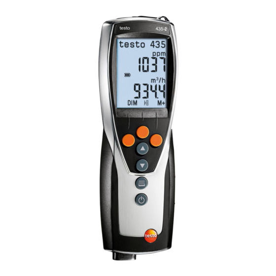
testo 435
Multifunktions-Messgerät
Inhalt
de
en
Werbung
Kapitel
Inhaltsverzeichnis

Verwandte Anleitungen für testo 435


Inhaltszusammenfassung für testo 435
-
Seite 1: Inhaltsverzeichnis
Speicher (nur 435-2 / -4) ..........18 6.2.2 Messreihe (nur 435-2 / -4) ..........19 6.2.3 Mittelwert (nur 435-2 / -4) ..........20 6.2.4 P = 0 (nur 435-3 / -4) ............21 6.2.5 Berechnung ..............21 6.2.6 Parameter ..............22 6.2.7 Zyklisch Drucken (nur 435-1/-3) ........24 Messen ..............25... -
Seite 2: Allgemeine Hinweise
Allgemeine Hinweise Allgemeine Hinweise Dieses Kapitel gibt wichtige Hinweise zur Nutzung der vorliegenden Dokumentation. Diese Dokumentation enthält Informationen, die für einen sicheren und effizienten Einsatz des Produkts beachtet werden müssen. Lesen Sie diese Dokumentation aufmerksam durch und machen Sie sich mit der Bedienung des Produkts vertraut, bevor Sie es einsetzen. - Seite 3 Allgemeine Hinweise 3 Kurzschreibweise In diesem Dokument wird eine Kurzschreibweise verwendet, um Handlungs- schritte (z. B. den Aufruf einer Funktion) darzustellen. Beispiel: Funktion „Gerätedaten“ aufrufen Kurzschreibweise: Gerät Ger.-Dat. Erforderliche Handlungsschritte: die Funktion Gerät wählen. Auswahl bestätigen. die Funktion Ger.-Dat. wählen. Auswahl bestätigen.
-
Seite 4: Sicherheitshinweise
Dabei die vorgegebenen Handlungsschritte einhalten. Aus Sicherheitsgründen nur Original-Ersatzteile von Testo ver- wenden. Fachgerecht entsorgen Defekte Akkus / leere Batterien an den dafür vorgesehenen Sammelstellen abgeben. Produkt nach Ende der Nutzungszeit an Testo senden. Wir sorgen für eine umweltschonende Entsorgung. -
Seite 5: Bestimmungsgemäße Verwendung
Setzen Sie dass Produkt nur für die Bereiche ein, für die es konzipiert wurde. Im Zweifelsfall bitte bei Testo nachfragen. Das testo 435 ist ein kompaktes Multifunktions-Messgerät zur Messung von Temperatur, Feuchte und Strömung. Das Produkt wurde für folgende Aufgaben / Bereiche konzipiert: ·... -
Seite 6: Produktbeschreibung
Im Konfigurationsmodus: Wert erhöhen, Option wählen Anzeige der 2. Messwertzeile wechseln Im Konfigurationsmodus: Wert verringern, Option wählen Daten drucken Nur 435-1/-3: Ist die Funktion Zyklisches Drucken aktiviert, wird die programmierte Messreihe gestartet. Gerät einschalten, Displaybeleuchtung ein-/ausschalten; Gerät ausschalten (gedrückt halten) -
Seite 7: Funktionstasten (Belegung Abhängig Von Profil Und Einstellung)
Menüpunkt „Zeitliche Mittelwertbildung“ öffnen Mittl Menüpunkt „Messreihe“ öffnen (nur 435-2/-4) Messr Messreihe starten (nur 435-2/-4) Start Messreihe beenden (nur 435-2/-4), Zyklisches Drucken beenden (nur 435-1/-3) Ende Werte speichern (nur 435-2/-4) Messreihe „Turb“ aktivieren (nur 435-2/-4 mit gestecktem Turbulenzgradfühler) Turb Menüpunkt „Flächen“ öffnen Fläch... -
Seite 8: Schnittstellen
3. Produktbeschreibung 3.2 Schnittstellen Infrarot-Schnittstelle Über die Infrarot-Schnittstelle an der Kopfseite des Geräts können Messdaten an einen Testo-Protokolldrucker gesendet werden. USB-Schnittstelle Über die USB-Schnittstelle an der Kopfseite des Geräts kann das Netzteil (Zubehör) zur Spannungsversorgung des Geräts angeschlossen werden. Geräte mit Speicher: Mess- / Gerätedaten können über die USB-Schnittstelle mit einem PC ausgetauscht werden. -
Seite 9: Inbetriebnahme
4. Inbetriebnahme 9 Inbetriebnahme Dieses Kapitel beschreibt die Handlungsschritte, die zur Inbetriebnahme des Produkts erforderlich sind. Display-S S chutzfolie e e ntfernen: Schutzfolie vorsichtig abziehen. Batterien / Akkus u u nd F F unkmodul ( ( Zubehör) e e inlegen: Die beiden Schrauben auf der Rückseite des Geräts lösen und Batteriefachdeckel abnehmen. -
Seite 10: Bedienung
5. Bedienung Bedienung Dieses Kapitel beschreibt die Handlungsschritte, die beim Einsatz des Produkts häufig ausgeführt werden. 5.1 Fühler anschließen Steckbare Fühler Steckbare Fühler müssen vor dem Einschalten des Messgeräts angeschlossen werden, damit diese vom Messgerät erkannt werden. Anschlussstecker des Fühlers in die Fühlerbuchse des Messgeräts stecken. -
Seite 11: Displaybeleuchtung
5. Bedienung 11 Gerät a a usschalten: gedrückt halten (ca. 2s), bis das Display erlischt. 5.3 Displaybeleuchtung Displaybeleuchtung e e in- / / ausschalten: Das Gerät ist eingeschaltet. drücken. -
Seite 12: Gerät Einstellen
6. Gerät einstellen Gerät einstellen Dieses Kapitel beschreibt die Handlungsschritte, die zur Anpassung des Mess- geräts an spezielle Messaufgaben erforderlich sind. 6.1 Konfigurationsmenü Im Konfigurationsmenü werden die Grundeinstellungen des Messgeräts vor- genommen. Konfigurationsmenü ö ö ffnen: Das Gerät befindet sich in der Messansicht. gedrückt halten (ca. -
Seite 13: Einheiten
6. Gerät einstellen 13 6.1.2 Einheiten Vordefinierte Systeme und individuelle Einstellmöglichkeiten: Messgröße System ISO System US Individuelle Einstellmöglichkeiten Temperatur °C °F °C, °F Druck inchH2O mbar, Pa, hPa, kPa, inchH2O Strömung m/s, fpm Volumenstrom m³/h ft³/min m³/h, l/s, ft³/min Länge inch mm, inch Einheiten e e instellen:... -
Seite 14: Batterietyp
6. Gerät einstellen Batterietyp Um eine korrekte Anzeige der Batteriekapazität zu gewährleisten, muss der ver- wendete Batterietyp eingestellt werden. Batterietyp e e instellen: Das Konfigurationsmenü ist geöffnet, Konfig. wird angezeigt. Gerät Bat-Typ Batterie oder Akku wählen und mit bestätigen. Auto OFF Ist Auto OFF eingeschaltet, schaltet sich das Gerät nach 10min ohne Tasten- betätigung automatisch aus. -
Seite 15: Fühler
6. Gerät einstellen 15 6.1.4 Fühler Funk Funkfühler dürfen nur in Ländern verwendet werden, in denen sie zugelassen wurden (siehe Anwendungshinweise zum Funkfühler). Zur Verwendung von Funkfühlern ist ein Funkmodul erforderlich (Zubehör). Das Gerät kann mit maximal drei Funkfühlern eine Verbindung herstellen. Jeder Funkfühler besitzt eine Fühler-ID (RF-ID). - Seite 16 Kanal-Nr. zuordnen oder Funktion mit verlassen, ohne die Fühlerkonfiguration zu ändern. Abgleich Feuchtefühler (nur 435-2/-4) Die Funktion ist nur verfügbar, wenn ein Feuchtefühler gesteckt ist. Die Abgleichwerte können auf die Werkseinstellungen zurückgesetzt werden (Reset). Ein 2-Punkt-Abgleich kann durchgeführt werden.
-
Seite 17: Language
6. Gerät einstellen 17 Te-Typ Die im Gerät hinterlegte Fühlerkennlinie kann auf den verwendeten Fühlertyp eingestellt werden. Fühlertyp e e instellen: Das Konfigurationsmenü ist geöffnet, Konfig. wird angezeigt. Fühler Te-Typ den gewünschten Fühlertyp wählen und mit bestätigen. 6.1.5 Language Sprache e e instellen: Das Konfigurationsmenü... -
Seite 18: Menüübersicht Testo
Internen Drucksensor nullen Fläche Form, Querschnittsfläche, K-Faktor einstellen Berechnung Berechnung Volumenstrom, Differenztemperatur de-/aktivieren; 435-3 zusätzlich: Berechnung Strömung de-/aktivieren Parameter Bezugsdruck einstellen; 435-3 zusätzlich: Bezugstemperatur, - feuchte einstellen Zykl. Drucken Zyklisches Drucken de-/aktivieren Kanalm. P = 0 (nur 435-3) Internen Drucksensor nullen Strömung (nur 435-3) -
Seite 19: Speicher (Nur 435-2/-4)
6. Gerät einstellen 19 6.2.1 Speicher (nur 435-2/-4) Messort Der aktive Messort kann geändert werden. Es können max. 99 Messorte angelegt werden. Die nummerischen Messortbezeichnungen (01 - 99) können über die PC-Software in beliebige Texte (max. 10 Zeichen) geändert werden. -
Seite 20: Messreihe (Nur 435-2/-4)
6. Gerät einstellen 6.2.2 Messreihe (nur 435-2/-4) Eine Messreihe kann programmiert und de- / aktiviert werden: Bezeichnung Beschreibung Messreihe ausgeschaltet: Messwerte können manuell gespeichert werden AUTO Automatische Messreihe: Messtakt (mind. 1s) und Anzahl Messwerte frei einstellbar. Turb Automatische Messreihe für Turbulenzgradmessung (Nur bei gestecktem Turbulenz- gradfühler verfügbar): Messtakt (1/5s) und Messdauer (180s) fest vorgegeben. -
Seite 21: Mittelwert (Nur 435-2/-4)
Mittel punktuell Messwerte aufnehmen. Pick Mittelwertbildung beenden. Ende 6.2.4 P = 0 (nur 435-3/-4) Der interne Drucksensor kann genullt werden. Internen D D rucksensor n n ullen: Das Hauptmenü ist geöffnet, Menü wird angezeigt. P = 0 6.2.5 Berechnung Bei eingeschalteter Berechung können aus den Messwerten eines Fühlers weitere Größen mit berechneten Werten angezeigt werden. - Seite 22 6. Gerät einstellen Folgende Größen können berechnet werden: · Strömungsgeschwindigkeit (nur 435-3/-4) · Volumenstrom · Taupunkt (unterhalb 0°Ctd / 32°Ftd werden Frost- / -Reif-Punkttemperaturen angezeigt.) · Psychrometrische Temperatur Ebenso besteht die Möglichkeit, die Differenz aus zwei Messkanälen zu berech- nen (Delta). Dies ist nur möglich, wenn die gewählten Messkanäle die gleiche Einheit besitzen.
- Seite 23 Querschnittsfläche A). Die Dimensionen der Flächen können im Gerät ange- passt werden. Eine neue Zuordnung der Formen ist über die PC-Software möglich (nur 435-2 / -4). Zu jeder Fläche wird ein Korrekturfaktor hinterlegt. Wenn Teile einer Fläche bedeckt sind (z. B. Gitterstäbe an Lüftungsöffnungen), kann dies über den Korrekturfaktor herausgerechnet werden.
-
Seite 24: Zyklisch Drucken (Nur 435-1/-3)
Ausdruck kann programmiert werden. Dies ermöglicht die Aufnahme von Messwerten (max. 999) in einem vorgegebenen Messtakt (min. 1min). Die Messwerte werden an einen Testo-Protokolldrucker gesendet. Zyklisches D D rucken a a ktivieren / Messreihe p p rogrammieren: Das Hauptmenü ist geöffnet, Menü wird angezeigt. -
Seite 25: Messen
ARAMETER Messung d d urchführen: Das Gerät befindet sich in der Messansicht. Die Messreihe AUTO bzw. TURB ist nicht aktiviert (nur 435-2/-4). Fühler positionieren und Messwerte ablesen. Anzeige O O bere M M esskanal-Z Z eile ä ä ndern: drücken. - Seite 26 - Unter dem aktiven Messort wird ein Messprotokoll mit den Messwerten aller verfügbaren Messkanäle angelegt. Zeitliche M M ittelwertbildung d d urchführen: Die Mittelwertbildung erfolgt als gleitender Mittelwert, Einzelwerte werden nicht angezeigt. 435-1/-3: drücken, 435-2/-4: Mittel Mittl zeitlich Mittelwertbildung starten. Start Mittelwertbildung stoppen.
- Seite 27 Das Gerät befindet sich in der Messansicht und Zyklisches Drucken ist aktiviert. Zyklisches Drucken mit starten. - Die Messreihe startet. Die Messwerte werden an den Testo-Protokoll- drucker übertragen. - Die Messung läuft, bis ein Abbruch mit erfolgt oder bis das End- Stopp kriterium eintritt (Anzahl Messwerte erreicht).
-
Seite 28: Wartung Und Pflege
8. Wartung und Pflege Wartung und Pflege Dieses Kapitel beschreibt die Handlungsschritte, die zur Erhaltung der Funktionsfähigkeit und zur Verlängerung der Lebensdauer des Produkts beitragen. Gehäuse r r einigen: Gehäuse bei Verschmutzung mit einem feuchten Tuch (Seifenlauge) reinigen. Keine scharfen Reinigungs- oder Lösungsmittel verwenden! Batterie / Akku w w echseln: Gerät ist ausgeschaltet. -
Seite 29: Fragen Und Antworten
· Stromversorgung war für längere Zeit · Geräteeinstellungen neu vornehmen. nicht mehr korrekt unterbrochen Falls wir Ihre Frage nicht beantworten konnten: Wenden Sie sich bitte an Ihren Händler oder den Testo-Kundendienst. Kontaktdaten finden Sie im Garantieheft oder im Internet unter www.testo.com . -
Seite 30: Technische Daten
Flügelrad 60mm: fühlerabhängig 0.01m/s 0...+20m/s Strömungsgeschwindig- 0...+20m/s fühlerabhängig 0.01m/s keit/Hitzdrahtsonde Druck/Absolutdruck- 0...+2000hPa fühlerabhängig 0.1hPa sonde CO2/IAQ-Sonde 0...+10000ppm fühlerabhängig 1ppm Lux/Luxfühler (nur 0...100000Lux fühlerabhängig 1Lux testo 435-2/-4) Druck/interner Differenz- 0...+25hPa ±0.02hPa (0...+2hPa) 0.01hPa drucksensor (nur ±1% v. Mw. (restl. Bereich) testo 435-3/-4) -
Seite 31: Weitere Gerätedaten
Werte Fühleranschlüsse 1x Omega TE-Buchse, 1x Mini-DIN-Buchse, Funkmodul (Zubehör), Nur 435-3/-4: 2x Drucknippel Speicher Nur 435-2/-4: max. 99 Messorte, bis zu 10000 Messwerte (abhängig von Anzahl Messorte, Protokolle, Kanäle) Batteriestandzeit 160h (typisch Flügelrad-Messung) Spannungsversorgung 3x Mignon-Batterie (Lieferumfang)/-akku oder Netzteil (Zubehör) Gehäusematerial... -
Seite 32: Zubehör/Ersatzteile
Thermische Strömungssonde mit integrierter Temperatur- und Feuchtemessung, 12mm Durchmesser, inkl. Teleskop max. 745mm 0635 1535 Behaglichkeits-Sonde für Turbulenzgradmessung, mit Teleskop und Stativ, erfüllt die Forderungen der DIN 1946 Teil 2 (nur testo 435-2/-4) 0628 0109 Lux-Fühler, zur Messung der Beleuchtungsstärke (nur testo 435-2/-4) 0635 0545... - Seite 33 Memory (435-2 / -4 only) ..........50 6.2.2 Measuring program (435-2 / -4 only) ......51 6.2.3 Mean (435-2 / -4 only) ............52 6.2.4 P = 0 (435-3 / -4 only) ............53 6.2.5 Calculation ..............53 6.2.6 Parameter ..............54 6.2.7 Cyclical Print (435-1/-3 only) ..........56 Measuring ............57...
-
Seite 34: General Notes
General notes General notes This chapter provides important advice on using this documentation. The documentation contains information that must be applied if the product is to be used safely and efficiently. Please read this documentation through carefully and familiarise yourself with the operation of the product before putting it to use. - Seite 35 General notes 35 Short form This document uses a short form for describing operating steps (e.g. calling up a function). Example: Calling up the “Instrument data” function Short form: Device Inst.data Steps required: Press to select the Device function. Confirm selection with Press to select the Inst.data function.
-
Seite 36: Safety Instructions
Ensure correct disposal Take faulty rechargeable batteries/spent batteries to the collection points provided for them. Send the product back to Testo at the end of its useful life. We will ensure that it is disposed of in an environmentally friendly manner. -
Seite 37: Intended Purpose
Use the product only for those applications for which it was designed. Ask Testo if you are in any doubt. testo 435 is a compact, multifunction measuring instrument for measuring temperature, humidity and flow rate. The product was designed for the following tasks/applications: ·... -
Seite 38: Product Description
Change display of the 2 reading line In configuration mode: Decrease value, select option Print data 435-1/-3 only: If the Cyclical Printing function is activated, the programmed measuring program is started. Switch instrument on, switch display light on/off; switch instrument off (press and hold) - Seite 39 Open menu item “Measuring program“ (435-2/-4 only) 435> Measp Start test series (435-2/-4 only) Start End test series (435-2/-4 only), End Cyclical Print (435-1/-3 only) Save values (435-2/-4 only) Save Activate “Turb“ test series (435-2/-4 only with attached turbulence probe) Turb Open menu item “Area”...
-
Seite 40: Interfaces
3. Product description 3.2 Interfaces Infrared interface Measurement data can be sent to a Testo printer via the infrared interface on the head of the instrument. USB interface The mains unit (accessory part) can be connected to the head of the instrument via the USB interface to power the instrument. -
Seite 41: Commissioning
4. Commissioning 41 Commissioning This chapter describes the steps required to commission the product. Removing t t he p p rotective f f ilm o o n t t he d d isplay: Pull the protective film off carefully. Inserting b b atteries/rechargeable b b atteries a a nd a a r r adio m m odule ( ( accessory part): Undo the two screws on the rear of the instrument and lift off the battery compartment cover. -
Seite 42: Operation
5. Operation Operation This chapter describes the steps that are executed frequently when using the product. 5.1 Connecting a probe Plug-in probes Plug-in probes must be connected before the measuring instrument is switched on so that they are recognised by the instrument. Insert the connector of the probe into the probe socket of the measuring instrument. -
Seite 43: Display Light
5. Operation 43 Switching t t he i i nstrument o o ff: Press and hold (for approx. 2s) until the display goes out. 5.3 Display light Switching t t he d d isplay l l ight o o n/off: The instrument is switched on. -
Seite 44: Setting The Instrument
6. Setting the instrument Setting the instrument This chapter describes the steps that are required in order to adapt the measuring instrument for specific measuring tasks. 6.1 Configuration menu The basic settings for the measuring instrument are performed in the configuration menu. -
Seite 45: Units
6. Setting the instrument 45 6.1.2 Units Predefined systems and individual setting options: Parameter ISO system US system Individual setting options Temperature °C °F °C, °F Pressure inchH2O mbar, Pa, hPa, kPa, inchH2O Velocity m/s, fpm Volumetric flow rate m³/h ft³/min m³/h, l/s, ft³/min Length... -
Seite 46: Battery Type
6. Setting the instrument Battery type To ensure that the battery capacity is displayed correctly, the battery type used must be set. Setting t t he b b attery t t ype: The configuration menu is open, config. is displayed. Device Bat-type Press... -
Seite 47: Probe
6. Setting the instrument 47 6.1.4 Probe RadioC Radio probes may only be used in countries in which they have been Type Approved (see application information of the radio probe). A radio module (accessory part) is required for the use of radio probes. The instrument can establish a connection with a maximum of three radio probes. - Seite 48 , without changing the probe configuration. Humidity probe calibration (435-2/-4 only) This function is only available if a humidity probe is plugged in. The calibration values can be reset to the default settings (Reset). A 2-point calibration can be performed.
-
Seite 49: Language
6. Setting the instrument 49 Te-Type The probe characteristic curves stored in the instrument can be set for the probe type used. Setting p p robe t t ype: The configuration menu is open, Config. is displayed. Probe Te-Type Select the desired probe type with and confirm with 6.1.5 Language Setting t t he l l anguage:... - Seite 50 6. Setting the instrument Menu overview testo 435-1/-3 Profile menu items Function Standard P = 0 (nur 435-3) Zero internal pressure sensor Area Set form, cross-section area, K-factor Calc. Calculate volume flow, de/activate differential temperature; 435-3 additionally; De/activate flow calculation Parameter Set reference pressure;...
-
Seite 51: Memory (435-2/-4 Only)
Press to select the location to be activated and confirm with Protocol Saved measurement protocols can be printed out on a Testo printer (accessory part) via the infrared interface. Printing a a m m easurement p p rotocol: The main menu is open, Menu is displayed. -
Seite 52: Measuring Program (435-2/-4 Only)
6. Setting the instrument 6.2.2 Measuring program (435-2/-4 only) A measuring program can be programmed and activated/deactivated: Designation Description Measuring program switched off: Readings can be stored manually AUTO Automatic measuring program: The measuring cycle (min. 1s) and the number of readings can be set freely. -
Seite 53: Mean (435-2/-4 Only)
Pick Press to stop mean calculation. 6.2.4 P = 0 (435-3/-4 only) The internal pressure sensor can be zeroed. Zeroing t t he i i nternal p p ressure s s ensor: The main menu is open, Menu is displayed. - Seite 54 6. Setting the instrument The following variables can be calculated: · Flow velocity (435-3/-4 only) · Volumetric flow rate · Dew point (below 0°Ctd / 32°Ftd frost point temperatures are displayed) · Psychometric temperature It is also possible to calculate the difference between two measurement channels (Delta).
- Seite 55 A). The dimensions of the areas can be adapted in the instrument. It is possible to reassign the shapes using the PC software (435-2/-4 only). An offset factor is stored for each area. If parts of an area are covered (e.g.
-
Seite 56: Cyclical Print (435-1/-3 Only)
- The settings are applied and the last shape to be set is activated. 6.2.7 Cyclical Print (435-1/-3 only) The Cyclical Print function can be activated/deactivated. A measuring program for cyclical printing can be programmed. This enables readings (up to 999) to be printed in a defined measuring cycle (min. -
Seite 57: Measuring
Taking a a m m easurement: The instrument is in measurement view. The measuring program AUTO or TURB is not activated (435-2/-4 only). Put the probe in position and take the readings. Changing t t he u u pper m m easurement c c hannel l l ine d d isplay:... - Seite 58 Running t t he A A UTO o o r T T URB m m easuring p p rogram ( ( 435-2 2 /-4 4 o o nly): The instrument is in measurement view and the AUTO or TURB measuring program is activated.
-
Seite 59: Care And Maintenance
8. Care and maintenance 59 Care and maintenance This chapter describes the steps that help to maintain the functionality of the product and extend its service life. Cleaning t t he h h ousing: Clean the housing with a moist cloth (soap suds) if it is dirty. Do not use aggressive cleaning agents or solvents! Changing t t he b b attery/rechargeable b b attery: Instrument is switched off. -
Seite 60: Questions And Answers
· Re-enter instrument settings. no longer correct long time. If we are unable to answer your question, please contact your dealer or Testo Customer Service. Contact details can be found on the guarantee card or on the Internet under www.testo.com . -
Seite 61: Technical Data
Depends on probe 0.1hPa pressure probe CO2/IAQ probe 0...+10000ppm Depends on probe 1ppm Lux/Lux probe 0...100000Lux Depends on probe 1Lux (testo 435-2/-4 only) Pressure/internal 0...+25hPa ±0.02hPa (0...+2hPa) 0.01hPa differential pressure probe ±1% of reading (rest of range) (testo 435-3/-4 only) - Seite 62 Probe connections 1x Omega TC socket, 1x Mini-DIN socket, radio module (accessory), 435-3/-4 only: 2x pressure nipple Memory 435-2/-4 only: max. 99 locations, up to 10000 readings (depending on number of locations, protocols, channels) Battery life 160h (typical for vane measurement)
-
Seite 63: Accessories/Spare Parts
(testo 435-2/-4 only) 0430 9735 Absolute pressure probe 2000hPa 0638 1835 Pressure dew point probe for measurements in compressed air systems (testo 435-2/-4 only) 0636 9835 Hot wire probe for m/s and °C, probehead 7.5mm diameter, telescopic to max. 820mm 0635 1025 IAQ probe to assess Indoor air quality, CO“, humidity, temperature and... - Seite 64 AG Postfach 11 40, 79849 Lenzkirch Testo-Straße 1, 79853 Lenzkirch Telefon: (07653) 681-0 Fax: (07653) 681-100 E-Mail: info@testo.de Internet: http://www.testo.com 0977.4350/02/T/dr/13.09.2005...