Werbung
Verfügbare Sprachen
Verfügbare Sprachen
Quicklinks
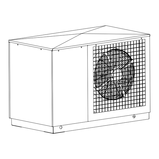
LAK 10M
Luft/Wasser-
Wärmepumpe für
Außenaufstellung
Bestell-Nr. / Order no. / N
Air-to-Water Heat
Pump for Outdoor
Installation
o
de commande : 452159.66.23
Montage- und
Gebrauchsanweisung
Installation and
Operating Instructions
Instructions d'installation
et d'utilisation
Pompe à chaleur
air-eau pour
installation
extérieure
FD 8810
Werbung
Kapitel
Fehlerbehebung

Inhaltszusammenfassung für Dimplex LAK 10M
- Seite 1 LAK 10M Montage- und Gebrauchsanweisung Installation and Operating Instructions Instructions d’installation et d’utilisation Luft/Wasser- Air-to-Water Heat Pompe à chaleur Wärmepumpe für Pump for Outdoor air-eau pour Außenaufstellung Installation installation extérieure Bestell-Nr. / Order no. / N de commande : 452159.66.23...
-
Seite 3: Inhaltsverzeichnis
Reinigung / Pflege ........................D-7 9.1 Pflege..............................D-7 9.2 Reinigung Heizungsseite ........................D-8 9.3 Reinigung Luftseite ..........................D-8 10 Störungen / Fehlersuche ......................D-8 11 Außerbetriebnahme / Entsorgung ....................D-8 12 Geräteinformation ........................D-9 13 Garantieurkunde......................... D-10 Anhang / Appendix / Annexes ......................A-I www.dimplex.de... -
Seite 4: Bitte Sofort Lesen
Bitte sofort lesen 1.2 Bestimmungsgemäßer Gebrauch 1.1 Wichtige Hinweise Dieses Gerät ist nur für den vom Hersteller vorgesehenen Ver- wendungszweck freigegeben. Ein anderer oder darüber hinaus ACHTUNG! gehender Gebrauch gilt als nicht bestimmungsgemäß. Dazu Das Gerät ist nicht für Frequenzumrichterbetrieb geeignet. zählt auch die Beachtung der zugehörigen Produktschriften. -
Seite 5: Verwendungszweck Der Wärmepumpe
Dampfschwaden am Luftausblas entstehen. Im Schaltkasten befinden sich die Netzanschlussklemmen, die Leistungsschütze, die Sanftanlauf-Einheit und die Anschluss- klemmen für den Fernversteller. Die Bedienung der Wärmepumpe erfolgt über den im Lieferum- fang enthaltenen Fernversteller (siehe hierzu auch Punkt 8.). www.dimplex.de... -
Seite 6: Transport
Transport Aufstellung ACHTUNG! 5.1 Allgemein Die Wärmepumpe darf beim Transport nur bis zu einer Neigung von 45° (in jeder Richtung) gekippt werden. Das Gerät ist grundsätzlich auf einer dauerhaft ebenen, glatten und waagerechten Fläche aufzustellen. Dabei sollte der Rahmen Der Transport zum endgültigen Aufstellungsort sollte mit dem (mit seinen Auflageflächen) vollflächig am Boden anliegen, um Holzrost erfolgen. -
Seite 7: Montage
Auslösung aller Außenlei- belle angegebene maximale Temperaturspreizung zwischen ter, vorzusehen (Auslösestrom gemäß Geräteinformation). Heizungsvor- und Rücklauf ergibt. Die Temperaturspreizung ist möglichst nahe an der Wärmepumpe zu messen. Bei monoener- getischen Anlagen ist der Heizstab zu deaktivieren. www.dimplex.de... -
Seite 8: Funktionsbeschreibung
Funktionsbeschreibung Wärmequellen- max. Temperaturspreizung temperatur zwischen Heizungsvor- und 8.1 Fernversteller-Wärmepumpe Rücklauf -20° C -15° C Mit dem im Gebäudeinneren platzierten Fernversteller kann die -14° C -10° C Wärmepumpe ein- und ausgeschaltet werden. Ausschalten be- -9° C -5° C deutet hierbei das Schalten in eine „Standby“-Funktion, d.h. so -4°... -
Seite 9: Steuerplatine
1 Stunde der Ausgang für den 2. Wärmeer- zeuger zugeschaltet. Eine Wiedereinschaltung der Wärme- pumpe ist erst nach einer Mindeststandzeit von 5 Minuten möglich. Bei einer Vorlauftemperatur von ca. 60 °C, bzw. bei zu niedriger Lufttemperatur schaltet die Wärmepumpe aus. www.dimplex.de... -
Seite 10: Reinigung Heizungsseite
10 Störungen / Fehlersuche 9.2 Reinigung Heizungsseite Durch Eindringen von Sauerstoff in das Heizwasser können sich, Diese Wärmepumpe ist ein Qualitätsprodukt und sollte störungs- insbesondere bei Verwendung von Stahlkomponenten, Oxydati- und wartungsfrei arbeiten. Tritt dennoch eine Störung auf, über- onsprodukte (Rost) bilden. Diese gelangen über Ventile, Um- prüfen Sie anhand der folgenden Hinweise, ob Sie die Störung wälzpumpen oder Kunststoffrohre in das Heizsystem. -
Seite 11: Geräteinformation
12 Geräteinformation Geräteinformation für Luft/Wasser-Heiz-Wärmepumpen Typ- und Verkaufsbezeichnung LAK 10M Bauform Ausführung Kompakt Schutzart nach EN 60 529 IP 24 Aufstellungsort Außen Leistungsangaben Temperatur-Betriebseinsatzgrenzen: bis 58 +/- 2 / ab 18 Heizwasser-Vorlauf / -Rücklauf °C / °C Luft (Wärmequelle) °C... -
Seite 12: Garantieurkunde
Teile ersetzt werden. Durch Art oder Ort des Einsatzes des Systemtechnik-Kundendienst erfahren Sie über die zentrale Ser- Gerätes oder schlechte Zugänglichkeit des Gerätes bedingte au- vicehotline der Glen Dimplex Deutschland GmbH. ßergewöhnliche Kosten der Mängelbeseitigung werden nicht übernommen. Der freie Gerätezugang muss durch den Endab- Glen Dimplex Deutschland GmbH nehmer gestellt werden. - Seite 22 E-10...
- Seite 32 F-10...
- Seite 33 4.2 Monoenergetische Anlage und Warmwasserbereitung / Mono-energetic system and domestic hot water function / Installation monoénergétique et préparation de l’eau chaude ..........A-IX 4.3 Legende / Legend / Légende........................A-X Konformitätserklärung / Declaration of Conformity / Déclaration de conformité ....A-XI www.dimplex.de...
-
Seite 37: Last / Load / Charge
3.2 Last / Load / Charge www.dimplex.de... -
Seite 38: Anschlussplan / Terminal Diagram / Schéma De Branchement
3.3 Anschlussplan / Terminal diagram / Schéma de branchement A-VI... -
Seite 39: Legende / Legend / Légende
Les composants sont intégrés à la télécommande –––––– werksseitig verdrahtet Wired ready for use câblé départ usine - - - - - - bauseits bei Bedarf anzuschließen To be connected by the customer as required à raccorder par le client au besoin www.dimplex.de A-VII... -
Seite 40: Hydraulische Prinzipschemen / Hydraulic Block Diagrams / Schémas Hydrauliques
4 Hydraulische Prinzipschemen / Hydraulic block diagrams / Schémas hydrauliques 4.1 Monoenergetische Anlage / Mono-energetic system / Installation monoénergétique A-VIII... -
Seite 41: Monoenergetische Anlage Und Warmwasserbereitung / Mono-Energetic System And Domestic Hot Water Function / Installation Monoénergétique Et Préparation De L'eau Chaude
4.2 Monoenergetische Anlage und Warmwasserbereitung / Mono-energetic system and domestic hot water function / Installation monoénergétique et préparation de l’eau chaude www.dimplex.de A-IX... -
Seite 42: Legende / Legend / Légende
4.3 Legende / Legend / Légende Überströmventil Overflow valve Soupape de trop-plein Sicherheitsventilkombination Safety assembly Combinaison de soupapes de sécurité Umwälzpumpe Circulating pump Pompe de circulation Ausdehnungsgefäß Expansion vessel Vase d’expansion raumtemperaturgesteuertes Room temperature-controlled Valve réglée en fonction de la Thermostatventil thermostat/valve température ambiante... -
Seite 43: Konformitätserklärung / Declaration Of Conformity / Déclaration De Conformité
5 Konformitätserklärung / Declaration of Conformity / Déclaration de conformité www.dimplex.de A-XI... - Seite 44 Glen Dimplex Deutschland GmbH Irrtümer und Änderungen vorbehalten. Geschäftsbereich Dimplex Subject to alterations and errors. Am Goldenen Feld 18 Sous réserve d’erreurs et modifications. D-95326 Kulmbach +49 (0) 9221 709 565 www.dimplex.de...


