Inhaltsverzeichnis
Werbung
Quicklinks
Service Manual
Grundig AG
- Geschaftsbereich Buroelektronik
- Kurgartenstr. 37 - W-8510 Furth/Bay.
1/92
Mit * gekennzeichneter Text gilt nur fur Dt 2600
The text marked with * is only for Dt 2600
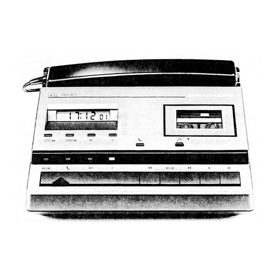
Abb. 1
inhaltsverzeichnis
Bedienorgane
Zubehor
Subjektive Funktionsprufung
Servicetips
HF-Einstreuung
Zerlegen des Gerates in Bausteine
10
Verwendete Abkurzungen
11
Uberschiagige Priifung Laufwerk
12
Steuerung Magnete
13.
Uberpriifung bzw. Korrektur erforderliche
Einstellungen Kopfjustage, Bandgeschwindigkeit
14.
+ Kontrolle Betriebsspannungen
OmOn
rab
wh
-
15
Kontrolle Wiedergabeverstarker uber
Index-Generator
16
KontrolleAufnahmeverstarker Mikrofon, Telefon",
VM-Oszillator und Loschkopf
17
Funktionspegel an|C's
18
IC3
19
Funktionspegel IC 101/102
20
= Kontrolle Mikrofon GDM 754
21
~Netzteil 680
22
Anschlusse
23
LP Display/Regler
24
Schaltbild Dt 2600
25
Schaltbild Dit 2601
26
~=Erlauterungen Schaltbild Dt 2601
27
~ Schaltbild GDM 754C
28
'Telefonadapter 246 (nicht GB)
29
~=Telefonadapter 244
30
~=©Telefonadapter 246 GB
31. ~~ Ersatzteilliste
Fig. 1
Seite
Contents
Page
a
1
2
2
2
:
2.
a
3
2
3
4
ig
!
5
Accessories
7
4-6
6
8-10
11
7
1
12
8
2
12
Q
12
13
10
13
14
11
14
15
12
15
138
Checks and Corrections
17
17
19
14.
Checking operating voltages,
;
currents and motor electronics
19
15
Checking playback amplifier using
21
index generator
21
16
23
23
23
17.
7
23
24
16°
IGS
24
25
. 19
Function level IC 101/102
25
26
20
26
27
21
2/
28
22
28
29
23
Circuit board Display/Control panel
29
30
24
:
30
31
25
31
32
26
Legend circuit diagram Dt 2601
32
33
33
34
28
34
34
29
34
35
30.
Coupling Unit 246 GB
che
36
31
36
Werbung
Inhaltsverzeichnis


