EKOM DK50 2V/50/M Benutzerhandbuch
Vorschau ausblenden
Andere Handbücher für DK50 2V/50/M:
- Benutzerhandbuch (520 Seiten) ,
- Benutzerhandbuch (352 Seiten) ,
- Benutzerhandbuch (156 Seiten)
Inhaltsverzeichnis
Werbung
Verfügbare Sprachen
Verfügbare Sprachen
Quicklinks
Werbung
Inhaltsverzeichnis
Fehlerbehebung

Verwandte Anleitungen für EKOM DK50 2V/50/M


Inhaltszusammenfassung für EKOM DK50 2V/50/M
- Seite 1 USER MANUAL BENUTZERHANDBUCH NÁVOD NA POUŽITIE...
- Seite 3 COMPRESSOR DK50 2V/50 KOMPRESSOR DK50 2x2V/110 KOMPRESOR EKOM spol. s r. o. Priemyselná 5031/18 SK-921 01 Piešťany Slovak Republic tel.: +421 33 7967255 fax: +421 33 7967223 www.ekom.sk email: ekom@ekom.sk DATE OF LAST REVISION DATUM DER LETZTEN ÜBERARBEITUNG 10/2022 DÁTUM POSLEDNEJ REVÍZIE...
- Seite 4 CONTENTS ....................5 INHALT ......................74 OBSAH ......................143...
-
Seite 5: Inhaltsverzeichnis
CONTENTS CONTENTS GENERAL INFORMATION ......................6 CONFORMITY WITH THE REQUIREMENTS OF THE EUROPEAN UNION ....6 SYMBOLS ........................6 DEVICE USE ........................7 GENERAL SAFETY INSTRUCTIONS ................7 STORAGE AND TRANSPORT CINDITIONS ..............9 PRODUCT DESCRIPTION ......................10 VARIANTS ........................10 ACCESSORIES ...................... -
Seite 6: General Information
GENERAL INFORMATION GENERAL INFORMATION Carefully read this user manual before using the product and carefully store it for future reference. The user manual aids in the proper use, including installation, operation and maintenance, of the product. The user manual corresponds to the configuration of the product and its compliance with applicable safety and technical standards at the time of its printing. -
Seite 7: Device Use
GENERAL INFORMATION Package handling label – fragile Package handling label – this side up Package handling label – keep dry Package handling label – temperature limits Package handling label – limited stacking Package label – recyclable material Manufacturer 3. DEVICE USE 3.1. -
Seite 8: General Instructions
GENERAL INFORMATION 4.1. Required qualification of the personnel Each user must be trained by the manufacturer or an organization authorized by the manufacturer or instructed on the device operation by other trained user. Installation, new settings, changes, extensions and repairs of the product may be performed by the manufacturer or an organization authorized by the manufacturer (hereinafter qualified technician). -
Seite 9: Storage And Transport Cinditions
GENERAL INFORMATION 5. STORAGE AND TRANSPORT CONDITIONS The compressor is shipped from the manufacturer in transport packaging. This protects the product from damage during transport. Potential for damage to pneumatic components. The compressor must be transported only when all air has been vented. Before moving or transporting the compressor, release all the air pressure from the tank and pressure hoses and drain condensate from the tank and from the condensate separator on the dryer. -
Seite 10: Product Description
PRODUCT DESCRIPTION PRODUCT DESCRIPTION 6. VARIANTS The compressor is manufactured according to its intended application in the following variants: DK50 2V/50/M Compressor with adsorption dryer DK50 2V/50S/M Compressor in cabinet with adsorption dryer Cabinet S50 It decreases noise level of the compressor... -
Seite 11: Accessories
*) submicrofilter with activated carbon *) - set FS 30A, in the standard configuration, this cannot be combined with a pressure regulator on products DK50 2V/50/M; please contact your supplier if you are interested in such set (with a regulator) -
Seite 12: Product Function
PRODUCT DESCRIPTION Compressor model Control schematic Article number System air outlet DK50 2V/50/M G 3/4“ 603002152-000 DK50 2x2V/110/M 1+1+1 Equipotential bonding socket The socket provides protective bonding. Type Name Article number Mains plug POAG-KBT6-EC 033400075-000 connector DK50 2V/50S/ DK50 2x2V/110S/M... - Seite 13 42 Power cord 22 Pressure gauge hose Position (28) applies to the DK50 2V/50/M, DK50 2x2V/110/M model without the cabinet; position (28) in the case of the DK50 2V/50 S/M, DK50 2x2V/110 S/M with the cabinet is a simple cover.
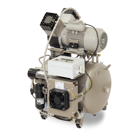
- Seite 14 PRODUCT DESCRIPTION Fig. 1: DK50 2V/50/M – Compressor with adsorption dryer NP-DK50 2V 50, 2x2V 110-AD-A-5_10-2022 10/2022...
- Seite 15 PRODUCT DESCRIPTION Fig. 2: DK50 2x2V/110/M – Compressor with adsorption dryer 10/2022 NP-DK50 2V 50, 2x2V 110-AD-A-5_10-2022...
- Seite 16 ADM 140/50 ADM 280/110 Position (28) applies to the DK50 2V/50/M, DK50 2x2V/110/M model without the cabinet; position (28) in the case of the DK50 2V/50 S/M, DK50 2x2V/110 S/M with the cabinet is a simple cover. For the cabinet model, the cable connected to the display (25) in the front panel of the cabinet is routed through the universal bushing (40).
- Seite 17 PRODUCT DESCRIPTION Fig. 4: Cabinet A - DK50 2V/50S/M 10/2022 NP-DK50 2V 50, 2x2V 110-AD-A-5_10-2022...
- Seite 18 PRODUCT DESCRIPTION B - DK50 2x2V/110S/M NP-DK50 2V 50, 2x2V 110-AD-A-5_10-2022 10/2022...
-
Seite 19: Technical Data
Compressors are designed for operation in dry, ventilated and dust-free indoor rooms under the following climactic conditions: +5°C to +40°C Temperature Relative humidity max. 70% Working pressure 6 – 8 bar DK50 2V/50/M DK50 2V/50S/M Nominal voltage V, Hz 230, 50 3x400, 50 230, 50... - Seite 20 TECHNICAL DATA Dependence of compressor output on working pressure NP-DK50 2V 50, 2x2V 110-AD-A-5_10-2022 10/2022...
- Seite 21 TECHNICAL DATA Working pressure 6 – 8 bar DK50 2V/50/M DK50 2V/50S/M Nominal voltage V, Hz 230, 50 3x400, 50 230, 50 3x400, 50 Frequency Capacity at 6 bar (FAD) -40°C l/min 6.0 – 8.0 6.0 – 8.0 Working pressure...
- Seite 22 TECHNICAL DATA Working pressure 8 – 10 bar DK50 2V/50/M DK50 2V/50S/M Nominal voltage V, Hz 230, 50 3x400, 50 230, 50 3x400, 50 Frequency Capacity at 8 bar (FAD) -20°C l/min 8.0 – 10.0 8.0 – 10.0 Working pressure...
- Seite 23 TECHNICAL DATA Working pressure 8 – 10 bar DK50 2V/50/M DK50 2V/50S/M Nominal voltage V, Hz 230, 50 3x400, 50 230, 50 3x400, 50 Frequency Capacity at 8 bar (FAD) -40°C l/min 8.0 – 10.0 8.0 – 10.0 Working pressure...
- Seite 24 TECHNICAL DATA Working pressure 6 – 8 bar DK50 2x2V/110/M DK50 2x2V/110S/M Nominal voltage V, Hz 230, 50 3x400, 50 230, 50 3x400, 50 Frequency Capacity at 6 bar (FAD) -20°C l/min 6.0 – 8.0 6.0 – 8.0 Working pressure Rated current 16.0 16.0...
- Seite 25 TECHNICAL DATA Working pressure 6 – 8 bar DK50 2x2V/110/M DK50 2x2V/110S/M Nominal voltage V, Hz 230, 50 3x400, 50 230, 50 3x400, 50 Frequency Capacity at 6 bar (FAD) -40°C l/min 6.0 – 8.0 6.0 – 8.0 Working pressure Rated current 16.0 16.0...
- Seite 26 TECHNICAL DATA Working pressure 8 – 10 bar DK50 2x2V/10/M DK50 2x2V/110S/M Nominal voltage V, Hz 230, 50 3x400, 50 230, 50 3x400, 50 Frequency Capacity at 8 bar (FAD) -20°C l/min 8.0 – 10.0 8.0 – 10.0 Working pressure Rated current 15.4 15.6...
- Seite 27 TECHNICAL DATA Working pressure 8 – 10 bar DK50 2x2V/10/M DK50 2x2V/110S/M Nominal voltage V, Hz 230, 50 3x400, 50 230, 50 3x400, 50 Frequency Capacity at 8 bar (FAD) -40°C l/min 8.0 – 10.0 8.0 – 10.0 Working pressure Rated current 15.4 15.6...
- Seite 28 TECHNICAL DATA FAD correction of capacity for altitude Capacity given in the form of FAD („Free Air Delivery“) applies to the following conditions: 20°C Altitude 0 m.n.m. Temperature Atmospheric pressure 101325 Pa Relative humidity To calculate FAD compressor capacity in dependence on altitude, it is necessary to apply correction factor according to the following table: Altitude [m.n.m.] 0 -1500...
-
Seite 29: Installation
Unpack the compressor from the packaging. For a compressor with a cabinet, remove the door held on the screws and for DK50 2V/50/M compressors, remove the connecting strip (17) in the lower part of the cabinet. Remove the cabinet from the compressor. - Seite 30 INSTALLATION Use the handles on the compressor to move the compressor as needed. Do not use other parts of the compressor (the air pump, cooler, etc.) for grip The number of persons required to handle the equipment must be matched to the weight of the device.
- Seite 31 INSTALLATION Fig. 6: Handling the compressor DK50 2V/50 10/2022 NP-DK50 2V 50, 2x2V 110-AD-A-5_10-2022...
- Seite 32 INSTALLATION DK50 2x2V/110 Remove the mounts used to secure the air pump in transport: use a 10 mm wrench to remove the upper bolts, and then use a 13 mm wrench to remove the lower side bolts (Fig. 7). Prior to installation, ensure that the compressor is free of all transport packaging and stabilizers to avoid any risk of damage to the product.
- Seite 33 INSTALLATION Fig. 7: Releasing the pump DK50 2V/50 DK50 2x2V/110 10/2022 NP-DK50 2V 50, 2x2V 110-AD-A-5_10-2022...
-
Seite 34: Pneumatic Connection
INSTALLATION 11. PNEUMATIC CONNECTION 11.1. Connecting to the compressed air outlet Route the pressure hose from the compressed air outlet (1) to the connected equipment. A G3/8" connection is installed. Route the pressure hose through the opening in the rear wall of the cabinet for cabinet- mounted compressors. - Seite 35 For a compressor in a cabinet, route the hose through the rear opening in the cabinet. Mount the condensate collection tank to the side panel or rear panel of the cabinet. Fig. 10: Condensate drain DK50 2V/50/M DK50 2x2V/110/M 10/2022...
-
Seite 36: Electrical Connection
INSTALLATION Risk of damage to pneumatic components. Air hoses must not be broken. 12. ELECTRICAL CONNECTION The product is delivered with a cord equipped with a plug with earthing pin. With cabinet-mounted compressors, route the power cord through the opening in the back wall of the cabinet. -
Seite 37: Placement Of The Compressor In The Cabinet
INSTALLATION Disconnect the cabinet electrically from the compressor by pulling the connector from the outlet while the latch is released. Connect the display at the front door of the cabinet and then secure the cord to the display in the clamps (1) (Fig. - Seite 38 INSTALLATION Fig. 14: Positioning of the compressor for connections Make the pneumatic connections per Chapter 11.1. Connect the condensate collection tank per Chapter 11.3. Route the pressure hose, the condensate drain hose, and the power cord through the opening in the rear wall of the cabinet.
- Seite 39 Check to ensure the compressor is fully inserted into the cabinet using the control dimension (Fig. 16). Fig. 16: Positioning of the DK50 2V/50/M compressor in the cabinet Place the connecting strip (17) in its original position in the lower part of the cabinet.
- Seite 40 INSTALLATION Fig. 17: Connecting the display connector Fig. 18: DK50 2V/50S/M cabinet clamps 13.2. DK50 2x2V/110S/M (Fig. 4-B) Opening the upper cover Lift the upper cabinet cover grabbing it by its handle (26) so that the gas springs keep the cover open.
- Seite 41 INSTALLATION Check to ensure the display connector is removed prior to removing the front door as otherwise it could be damaged. Compressor placement Position the compressor within a distance of at least 500 mm from the cabinet to facilitate the movement of the hoses and the power cord within the cabinet (Fig.
- Seite 42 INSTALLATION Fig. 20: Positioning the compressor for electrical connections Electrically connect the compressor per Chapter 12. Insert the compressor with dryer into the cabinet so that the dryer fan fits into the cooling tunnel opening in the cabinet. ...
-
Seite 43: Commissioning
INSTALLATION Fig. 21: DK50 2x2V/110S/M cabinet clamps Connect the earthing conductor to the door and install the door on the cabinet and secure with 4 screws. 14. COMMISSIONING Make sure all transport stabilizers were removed. Check that all compressed air hose connections are correct (see chap. 11). ... -
Seite 44: Pneumatic And Electrical Diagrams
INSTALLATION 15. PNEUMATIC AND ELECTRICAL DIAGRAMS 15.1. Pneumatic diagram DK50 2V/50/M DK50 2x2V/110/M Description to pneumatic diagram: Inlet filter 10 Cooler Compressor 11 Cooler fan 12 Air tank Safety valve 13 Condensate drain valve Non-return valve 14 Outlet valve 15 Solenoid valve – regeneration Condensate separator 16 Solenoid valve –... -
Seite 45: Electrical Diagrams
INSTALLATION 15.2. Electrical diagrams DK50 2V/50/M 1/N/PE ~ 230V, 50Hz ELEKTRIC OBJECT OF 1st. CAT. DK50 2x2V/110/M 1/N/PE ~ 230V, 50Hz / 230V, 60Hz ELEKTRIC OBJECT OF 1st. CAT. Note: J** - Only connect the jumper for compressors without cabinet (see chap. 22.8). - Seite 46 INSTALLATION AD140 1/N/PE ~ 230V, 50Hz / 230V, 60Hz ~ 120V, 60Hz ELEKTRIC OBJECT OF 1st. CAT. Note: The dew point sensor (A1_1) is not included with the dryer; please contact your supplier for more information. NP-DK50 2V 50, 2x2V 110-AD-A-5_10-2022 10/2022...
- Seite 47 INSTALLATION AD280 1/N/PE ~ 230V, 50Hz / 230V, 60Hz ~ 120V, 60Hz ELEKTRIC OBJECT OF 1st. CAT. Note: The dew point sensor (A1_1) is not included with the dryer; please contact your supplier for more information. 10/2022 NP-DK50 2V 50, 2x2V 110-AD-A-5_10-2022...
- Seite 48 INSTALLATION AD500 1/N/PE ~ 230V, 50Hz / 230V, 60Hz ~ 120V, 60Hz ELEKTRIC OBJECT OF 1st. CAT. Note: The dew point sensor (A1_1) is not included with the dryer; please contact your supplier for more information NP-DK50 2V 50, 2x2V 110-AD-A-5_10-2022 10/2022...
- Seite 49 INSTALLATION Compressor cabinet 1/N/PE ~ 230V, 50Hz / 230V, 60Hz ELEKTRIC OBJECT OF 1st. CAT. DK50 2V/50/M DK50 2x2V/110/M Description to electrical diagrams: M1, M2 Compressor motor X2, X3 Socket E1, E2 Compressor fan Switch Fuse Service indicator F1, F2...
-
Seite 50: Operation
OPERATION OPERATION ONLY TRAINED PERSONNEL MAY OPERATE THE EQUIPMENT! Risk of electric shock. In case of emergency, disconnect the compressor from the mains (pull out the mains plug). Burn or fire hazard. Portions of the air pump and compressed air components between the air pump and the dryer may be hot and reach hazardous temperatures during compressor operation that may harm materials or operating staff. -
Seite 51: Switching On The Compressor
OPERATION 16. SWITCHING ON THE COMPRESSOR Start the compressor (without a cabinet) at the pressure switch (1) by turning the switch (2) to position “I.” This starts the compressor and fills the tank to the switching off pressure, which then shuts off the compressor. -
Seite 52: Ad Dryer
AD DRYER AD DRYER 18. PRINCIPLE OF OPERATION The dryer is controlled by a signal from the compressor pressure switch. When the compressor is running, compressed air enters the cooler where it is cooled, and a portion of the condensed moisture is separated in the integrated cyclical separator. Solenoid valve V3 is located in the bottom of the separator, and it drains off the condensate from the separator at regular intervals. -
Seite 53: User Interface/Settings
AD DRYER Operator’s position. No specific operator’s position is required. The operator may remain within range of a visual warning signal depending on actual operating conditions. Low pressure. This signal is active when the dryer pressure sensor reads low pressure in the dryer under the defined limit of 3 bar. - Seite 54 AD DRYER Symbol for chamber pre-filling – equalisation of pressure in chambers. Indication the device is operating Indication of an alarm state (on until the alarm state no longer exists) 19.2. Initial settings for the user interface The option to select language, time and date appears when the program is first launched. The service technician selects the given language, time and date during installation based on the geographic location of the dryer installation.
-
Seite 55: Main Screens
AD DRYER 19.4. Setting the drying mode during commissioning It is recommended to set the air-drying mode during commissioning. These settings are changed in the service menu in the SERVICE SETUP section. Access to the service menu is protected by a code. -
Seite 56: Home Screen
AD DRYER 20.1. Home screen Hour meter Current dew point* Dryer operating mode Service interval length menu Current pressure in dryer Switch to display dryer Switch language operation selection (*this information is only shown if the compressor is equipped with a dew point sensor) Basic information and measured parameters are shown on the dryer home screen. - Seite 57 AD DRYER 20.2. Dryer operation screen Operating hours indicator Hour meter Chamber designation Symbol chamber pressure equalisation phase Status icon for the right chamber Status icon for the left chamber Arrow to navigate back to the home screen The dryer operating hours indicator is located at the top of the screen. The dryer operation screen is also divided into 4 sections, which describe the dryer chamber working cycles using a graphical depiction of the operating states of each chamber.
-
Seite 58: Indication Of Maintenance And Alarm States
AD DRYER 20.4. Service menu screen The service menu is intended exclusively for service personnel. Access to individual service menu items is protected by the password 1992. 21. INDICATION OF MAINTENANCE AND ALARM STATES The adsorption dryer controller is capable of measuring selected parameters (pressure and pressure dew point in versions with a dew point sensor) and for assessing the basic dryer operating states. -
Seite 59: Alarm Conditions
AD DRYER 21.2. Warning - Service interval exceeded A red warning is shown (“Warning!”) once the service interval has lapsed. The service tile also lights up red. Pressing and holding the service interval field (min. 2 seconds) opens a scrolling menu showing all service intervals. - Seite 60 AD DRYER A high dew point alarm may appear when the unit is first placed into service. The alarm will persist until the dryer regenerates. The regeneration time of the dryer depends on many parameters of use of the device. Dryer regeneration should take no more than 24 dryer working hours.
-
Seite 61: Product Maintenance
PRODUCT MAINTENANCE PRODUCT MAINTENANCE 22. PRODUCT MAINTENANCE The operator should carry out device checks regularly in the intervals defined by applicable regulations. Test results must be recorded. The equipment has been designed and manufactured to keep maintenance to a minimum. The following work must be performed to preserve the proper and reliable operation of the compressor. -
Seite 62: Maintenance Intervals
PRODUCT MAINTENANCE 22.1. Maintenance intervals Performed operator qualified technician Set of replacement parts Chap. 24 000 h 20 000 h 16 000 h 12 000 h 10 000 h 8 000 h 6 000 h 4 000 h 2 000 h Once every 6 years Once every... - Seite 63 PRODUCT MAINTENANCE Performed qualified technician Set of replacement parts Chap. See the service manual 24 000 h 20 000 h 16 000 h 12 000 h 10 000 h 8 000 h 6 000 h 4 000 h 2 000 h Once every 6 years Once every...
- Seite 64 PRODUCT MAINTENANCE 22.2. Check of product operation Check air pump condition – the aggregates should be operating normally without excessive vibration or noise. Troubleshoot any problem or call in service personnel if trouble is detected. Visually inspect fan operation – the fans must be operating when the air pumps are running. Troubleshoot any problem or call in service personnel if trouble is detected.
-
Seite 65: Condensate Drain
Monitor the level in the vessel using the markings (depending on the volume of the vessel), and empty at least once a day. Fig. 23: Check of the condensate collection vessel DK50 2V/50/M DK50 2x2V/110/M 10/2022 NP-DK50 2V 50, 2x2V 110-AD-A-5_10-2022... - Seite 66 PRODUCT MAINTENANCE Switch off the compressor every time before emptying the vessel! Before the following checks it is required: For compressor variant with cabinet – unlock the door lock and open the cabinet door. 22.6. Check of safety valve ...
- Seite 67 PRODUCT MAINTENANCE 22.7. Inlet filter replacement Inlet filter replacement: Remove the locking spring (2). Pull out the rubber plug by hand (2). Remove the dirty intake filter (1). Insert a new filter and replace the rubber plug. Pre-filter replacement: ...
- Seite 68 PRODUCT MAINTENANCE Fig. 26: DK50 2V/50 230 V Fig. 27:DK50 2x2V/110 230 V NP-DK50 2V 50, 2x2V 110-AD-A-5_10-2022 10/2022...
- Seite 69 PRODUCT MAINTENANCE 22.9. Procedure for connecting a compressor to a new cabinet Prior to any maintenance or repair work, switch off the compressor and disconnect it from the mains (pull out the mains plug). The compressor in a cabinet requires that the jumper is not mounted in the terminal strip for correct operation (Fig.
-
Seite 70: Long-Term Shutdown
After removing the dew point sensor, blank off the place where the sensor was installed using the provided plug, sealed with the provided adhesive (applies to DK50 2V/50/M compressors). 23. LONG-TERM SHUTDOWN If the compressor is not going to be used for long period, it is recommended to drain all condensate from the air tank and switch on the compressor for about 10 minutes, keeping the drain valve open. -
Seite 71: Troubleshooting
TROUBLESHOOTING TROUBLESHOOTING Risk of electric shock. Before interfering with the equipment, first disconnect it from the mains (remove the power socket). Working with pressurised pneumatic components poses a risk of injury. Before interfering with the equipment, vent the air tank and the compressed air system to zero pressure. - Seite 72 TROUBLESHOOTING Dirty inlet filter Replace dirty filter with new filter Incorrect function of solenoid valve Repair or replace fan or coil Damaged piston bearing, piston Replace damaged bearing Compressor is rods, motor bearing noisy (knocking, Loose (cracked) dampening metal noises) Replace damaged spring element (spring) Replace fan...
-
Seite 73: Repair Service
TROUBLESHOOTING Check the moisture content of the air exiting the air tank (see the Technical data chapter) to prevent damage to connected downstream equipment. 25. REPAIR SERVICE Warranty and post-warranty repairs must be done by the manufacturer, its authorized representative, or service personnel approved by the supplier. Attention. - Seite 74 INHALT INHALT ALLGEMEINE INFORMATIONEN ....................75 KONFORMITÄT MIT DEN ANFORDERUNGEN DER EU ..........75 SYMBOLE ........................75 NUTZUNG DES GERÄTS ....................76 ALLGEMEINE SICHERHEITSANWEISUNGEN .............77 LAGERUNGS- UND TRANSPORTBEDINGUNGEN ............78 PRODUKTBESCHREIBUNG .......................79 VERSIONEN ........................79 ZUBEHÖR ........................80 PRODUKTFUNKTION ....................81 TECHNISCHE DATEN .........................88 INSTALLATION ...........................98 INSTALLATIONSBEDINGUNGEN .................98 ZUSAMMENBAU DES KOMPRESSORS ...............98 PNEUMATISCHER ANSCHLUSS ................
-
Seite 75: Allgemeine Informationen
ALLGEMEINE INFORMATIONEN ALLGEMEINE INFORMATIONEN Lesen Sie das Benutzerhandbuch vor der Nutzung des Produkts sorgfältig durch und bewahren Sie es auf. Das Benutzerhandbuch enthält Anleitungen zur korrekten Nutzung, Installation, Bedienung und Wartung des Produkts. Zum Zeitpunkt des Drucks entspricht das Benutzerhandbuch dem Produktdesign und erfüllt die geltenden Sicherheits- und Technikstandards. -
Seite 76: Nutzung Des Geräts
ALLGEMEINE INFORMATIONEN Sicherung Etikett für die Handhabung der Verpackung – zerbrechlich Etikett für die Handhabung der Verpackung – diese Seite nach oben Etikett für die Handhabung der Verpackung – trocken lagern Etikett für die Handhabung der Verpackung – Temperaturgrenzwerte Etikett für die Handhabung der Verpackung – Stapelbeschränkung Verpackungsetikett –... -
Seite 77: Allgemeine Sicherheitsanweisungen
ALLGEMEINE INFORMATIONEN 4. ALLGEMEINE SICHERHEITSANWEISUNGEN Das Produkt wurde entwickelt und hergestellt, um alle Risiken in Verbindung mit seiner Nutzung zu minimieren. Das Produkt ist für den Benutzer und die Umgebung sicher, wenn es gemäß seinem Verwendungszweck und den nachfolgend aufgeführten Anweisungen verwendet wird. 4.1. -
Seite 78: Lagerungs- Und Transportbedingungen
ALLGEMEINE INFORMATIONEN 5. LAGERUNGS- UND TRANSPORTBEDINGUNGEN Der Kompressor wird ab Hersteller in einer Transportverpackung versendet. Diese schützt das Produkt während des Transports vor Schäden. Beschädigungsgefahr für Pneumatikkomponenten! Der Kompressor darf nur transportiert werden, wenn die gesamte Luft abgelassen wurde. Vor dem Bewegen oder Transportieren des Kompressors entlassen Sie jegliche Druckluft aus dem Behälter und den Druckschläuchen und lassen Sie das Kondensat aus dem Behälter und dem Kondensatabscheider am Trockner ab. -
Seite 79: Produktbeschreibung
PRODUKTBESCHREIBUNG PRODUKTBESCHREIBUNG 6. VERSIONEN Der Kompressor ist gemäß seinem Verwendungszweck in den folgenden Modellen erhältlich: DK50 2V/50/M Kompressor mit Adsorptionstrockner Kompressor im Gehäuse mit Adsorptionstrockner DK50 2V/50S/M Gehäuse S50 Reduziert den Geräuschpegel des Kompressors DK50 2x2V/110/M Kompressor mit Adsorptionstrockner Kompressor im Gehäuse mit Adsorptionstrockner DK50 2x2V/110S/M Gehäuse S110... -
Seite 80: Zubehör
604014119-018* **) A –Submikrofilter mit Aktivkohle *) – Set FS 30A, in der Standardkonfiguration. Dies kann bei den Produkten DK50 2V/50/M nicht mit einem Druckregler kombiniert werden. Wenden Sie sich bitte an Ihren Lieferanten, wenn Sie Interesse an diesem Set (mit einem Regler) haben... -
Seite 81: Produktfunktion
PRODUKTBESCHREIBUNG Luftauslass des Kompressormodell Steuerschema Artikelnummer Systems DK50 2V/50/M G 3/4“ 603002152-000 DK50 2x2V/110/M 1+1+1 Potenzialausgleichsbuchse Die Buchse ermöglicht einen Potenzialausgleich. Verwendung Name Artikelnummer POAG-KBT6-EC Netzstecker 033400075-000 DK50 2V/50S/M DK50 2x2V/110S/M FLEXI-S/POAG-HK6 Zuleitung (1 m) 034110083-000 8. PRODUKTFUNKTION 8.1. Kompressor mit Adsorptionstrockner (Abb. - Seite 82 42 Zuleitungsschnur 22 Manometer-Schlauch Position (28) gilt für das Modell DK50 2V/50/M, DK50 2x2V/110/M ohne Schrank; Position (28) beim DK50 2V/50 S/M, DK50 2x2V/110 S/M mit Schrank ist eine einfache Abdeckung. Bei der Schrankausführung wird das mit dem Display (25) in der Vorderseite des Schranks verbundene Kabel durch die Universalbuchse geführt (40).
- Seite 83 PRODUKTBESCHREIBUNG Abb. 1: DK50 2V/50/M – Kompressor mit Adsorptionstrockner 10/2022 NP-DK50 2V 50, 2x2V 110-AD-A-5_10-2022...
- Seite 84 PRODUKTBESCHREIBUNG Abb. 2: DK50 2x2V/110/M – Kompressor mit Adsorptionstrockner NP-DK50 2V 50, 2x2V 110-AD-A-5_10-2022 10/2022...
- Seite 85 ADM 140/50 ADM 280/110 Position (28) gilt für das Modell DK50 2V/50/M, DK50 2x2V/110/M ohne Schrank; Position (28) beim DK50 2V/50 S/M, DK50 2x2V/110 S/M mit Schrank ist eine einfache Abdeckung. Bei der Schrankausführung wird das mit dem Display (25) in der Vorderseite des Schranks verbundene Kabel durch die Universalbuchse geführt (40).
- Seite 86 PRODUKTBESCHREIBUNG Abb. 4: Gehäuse A - DK50 2V/50S/M NP-DK50 2V 50, 2x2V 110-AD-A-5_10-2022 10/2022...
- Seite 87 PRODUKTBESCHREIBUNG B - DK50 2x2V/110S/M 10/2022 NP-DK50 2V 50, 2x2V 110-AD-A-5_10-2022...
-
Seite 88: Technische Daten
Die Kompressoren sind für den Betrieb in trockenen, belüfteten und staubfreien Innenräumen unter den folgenden klimatischen Bedingungen vorgesehen: +5 °C bis +40 °C Temperatur Relative Feuchtigkeit max. 70 % Arbeitsdruck 6 bis 8 bar DK50 2V/50/M DK50 2V/50S/M Nennspannung V, Hz 230, 50 3x400, 50 230, 50... - Seite 89 TECHNISCHE DATEN Abhängigkeit von Kompressorkapazität und Arbeitsdruck 10/2022 NP-DK50 2V 50, 2x2V 110-AD-A-5_10-2022...
- Seite 90 TECHNISCHE DATEN Arbeitsdruck 6 bis 8 bar DK50 2V/50/M DK50 2V/50S/M Nennspannung V, Hz 230, 50 3x400, 50 230, 50 3x400, 50 Frequenz Kapazität bei 6 bar (FAD) –40 °C l/min 6,0 – 8,0 6,0 – 8,0 Arbeitsdruck Nennstrom Motorleistung Volumen Drucklufttank m...
- Seite 91 TECHNISCHE DATEN Arbeitsdruck 8 bis 10 bar DK50 2V/50/M DK50 2V/50S/M Nennspannung V, Hz 230, 50 3x400, 50 230, 50 3x400, 50 Frequenz Kapazität bei 8 bar (FAD) –20 °C l/min 8,0 – 10,0 8,0 – 10,0 Arbeitsdruck Nennstrom Motorleistung Volumen Drucklufttank m...
- Seite 92 TECHNISCHE DATEN Arbeitsdruck 8 bis 10 bar DK50 2V/50/M DK50 2V/50S/M Nennspannung V, Hz 230, 50 3x400, 50 230, 50 3x400, 50 Frequenz Kapazität bei 8 bar (FAD) –40 °C l/min 8,0 – 10,0 8,0 – 10,0 Arbeitsdruck Nennstrom Motorleistung Volumen Drucklufttank m...
- Seite 93 TECHNISCHE DATEN Arbeitsdruck 6 bis 8 bar DK50 2x2V/110/M DK50 2x2V/110S/M Nennspannung V, Hz 230, 50 3x400, 50 230, 50 3x400, 50 Frequenz Kapazität bei 6 bar (FAD) –20 °C l/min 6,0 – 8,0 6,0 – 8,0 Arbeitsdruck Nennstrom 16,0 16,0 Motorleistung 2x1,2...
- Seite 94 TECHNISCHE DATEN Arbeitsdruck 6 bis 8 bar DK50 2x2V/110/M DK50 2x2V/110S/M Nennspannung V, Hz 230, 50 3x400, 50 230, 50 3x400, 50 Frequenz Kapazität bei 6 bar (FAD) –40 °C l/min 6,0 – 8,0 6,0 – 8,0 Arbeitsdruck Nennstrom 16,0 16,0 Motorleistung 2x1,2...
- Seite 95 TECHNISCHE DATEN Arbeitsdruck 8 bis 10 bar DK50 2x2V/110/M DK50 2x2V/110S/M Nennspannung V, Hz 230, 50 3x400, 50 230, 50 3x400, 50 Frequenz Kapazität bei 8 bar (FAD) –20 °C l/min 8,0 – 10,0 8,0 – 10,0 Arbeitsdruck Nennstrom 15,4 15,6 Motorleistung 2x1,2...
- Seite 96 TECHNISCHE DATEN Arbeitsdruck 8 bis 10 bar DK50 2x2V/110/M DK50 2x2V/110S/M Nennspannung V, Hz 230, 50 3x400, 50 230, 50 3x400, 50 Frequenz Kapazität bei 8 bar (FAD) –40 °C l/min 8,0 – 10,0 8,0 – 10,0 Arbeitsdruck Nennstrom 15,4 15,6 Motorleistung 2x1,2...
- Seite 97 TECHNISCHE DATEN FAD-Kapazitätskorrektur für Höhenlagen Die Kapazität in Form von FAD („Free Air Delivery“ = Volumenstrom bzw. Liefermenge) gilt für die folgenden Bedingungen: Höhenlage 0 m ü. M. 20 °C Temperatur Umgebungsdruck 101325 Pa Relative Feuchtigkeit Um die FAD-Kompressorkapazität in Abhängigkeit von der Höhenlage zu berechnen, muss der Korrekturfaktor gemäß...
-
Seite 98: Installation
Kompressoren DK50 2V/50/M die Anschlussleiste (17) im unteren Teil des Schranks. Entfernen Sie den Schrank vom Kompressor. Lösen Sie den Kompressor von der Palette: Lösen Sie bei den Kompressoren DK50 2V/50/M die Schrauben, bei den Kompressoren DK50 2x2V/110/M die Riemen (Abb. 5). - Seite 99 INSTALLATION Die Anzahl der Personen, die zum Umgang mit dem Gerät erforderlich sind, muss auf das Gewicht des Geräts abgestimmt sein. Abb. 5: Entfernen der Transporthalterungen DK50 2V/50 DK50 2x2V/110 10/2022 NP-DK50 2V 50, 2x2V 110-AD-A-5_10-2022...
- Seite 100 INSTALLATION Abb. 6: Handhabung des Kompressors DK50 2V50 NP-DK50 2V 50, 2x2V 110-AD-A-5_10-2022 10/2022...
- Seite 101 INSTALLATION DK50 2x2V/110 Entfernen Sie die Halterungen zur Transportsicherung des Aggregats: Entfernen Sie mit einem oberen Schrauben dann einem 13-mm- 10-mm-Schraubenschlüssel Schraubenschlüssel die unteren seitlichen Schrauben (Abb. 7). 10/2022 NP-DK50 2V 50, 2x2V 110-AD-A-5_10-2022...
- Seite 102 INSTALLATION Stellen Sie vor der Installation sicher, dass der Kompressor frei von Verpackungsmaterial und Stabilisatoren ist, um Schäden am Produkt zu vermeiden. Entfernen Sie alle für die Sicherung der Aggregate verwendeten Komponenten, nachdem der Kompressor am endgültigen Einsatzort installiert und nivelliert wurde.
-
Seite 103: Pneumatischer Anschluss
INSTALLATION 11. PNEUMATISCHER ANSCHLUSS 11.1. Anschluss an den Druckluftausgang Führen Sie den Druckluftschlauch vom Druckluftausgang (1) zur angeschlossenen Gerätschaft. A-G-1/2-Verbindung ist installiert Schließen Sie bei Kompressoren mit Trocknern den Kondensatablaufschlauch (1) an den Kondensatbehälter an. DK50 2V/50 DK50 2x2V/110 Abb. -
Seite 104: Kondensatablass Vom Trockner
Führen Sie bei einem Kompressor in einem Schrank den Schlauch durch die hintere Öffnung im Schrank. Montieren Sie den Kondensatsammelbehälter an der Seiten- oder an der Rückwand des Schranks. Abb. 10: Kondensatablauf DK50 2V/50/M DK50 2x2V/110/M NP-DK50 2V 50, 2x2V 110-AD-A-5_10-2022 10/2022... -
Seite 105: Elektrischer Anschluss
INSTALLATION Beschädigungsgefahr für Pneumatikkomponenten! Druckluftschläuche müssen unbeschädigt sein. 12. ELEKTRISCHER ANSCHLUSS Das Produkt wird mit einem Kabel mit Stecker und Erdungsstift geliefert. Führen Sie bei im Gehäuse montierten Kompressoren das Stromkabel durch die Öffnung in der Rückwand des Gehäuses. ... -
Seite 106: Platzieren Des Kompressors Im Gehäuse
INSTALLATION Schließen Sie den Stromanschluss des Schaltschranks an den Kompressor an, indem Sie den Stecker des mitgelieferten Netzkabels in eine Steckdose stecken. (Abb. 13) Unterbrechen Sie die den elektrischen Anschluss zwischen Schaltschrank und Kompressor, indem Sie den Stecker aus der Steckdose ziehen, während die Verriegelung gelöst ist. ... - Seite 107 INSTALLATION Positionieren Sie den Kompressor in einem Abstand von mindestens 500 mm vom Schrank, um die Bewegung der Schläuche und des Netzkabels im Schrank zu ermöglichen (Abb. 14). Abb. 14: Positionierung des Kompressors für Anschlüsse Stellen Sie die pneumatischen Anschlüsse gemäß Kapitel 11.1 her. ...
- Seite 108 Überprüfen Sie anhand des Kontrollmaßes (Abb. 16), dass der Kompressor vollständig in den Schrank eingesetzt ist. Abb. 16: Positionierung des Kompressors DK50 2V/50/M im Schaltschrank Bringen Sie die Anschlussleiste (17) an ihrer ursprünglichen Position im unteren Schrankbereich an.
- Seite 109 INSTALLATION Abb. 17: Anschließen des Displaysteckers Abb. 18: Schrankklemmen DK50 2V/50S/M 10/2022 NP-DK50 2V 50, 2x2V 110-AD-A-5_10-2022...
- Seite 110 INSTALLATION 13.2. DK50 2x2V/110S/M (Abb. 4 - B) Öffnen der oberen Abdeckung Heben Sie die obere Gehäuseabdeckung an, indem Sie den Griff (26) in die Hand nehmen, sodass die Gasfeder die Abdeckung geöffnet hält. Schließen Gehäuseabdeckung – Vorsicht beim besteht Fingerquetschgefahr! Entfernen der Vorderabdeckung des Gehäuses...
- Seite 111 INSTALLATION Abb. 20: Positionierung des Kompressors für elektrische Anschlüsse Schließen Sie den Kompressor gemäß Kapitel 12 an die Stromversorgung an. Setzen Sie den Kompressor mit einem Trockner in den Schrank ein, sodass der Trocknerventilator in die Öffnung des Kühltunnels im Gehäuse passt. ...
-
Seite 112: Inbetriebnahme
INSTALLATION Abb. 21: Schrankklemmen DK50 2x2V/110S/M Schließen Sie den Erdungsleiter an der Tür an und montieren Sie die Tür am Schrank und befestigen Sie sie mit 4 Schrauben. 14. INBETRIEBNAHME Stellen Sie sicher, dass alle Transporthilfen entfernt wurden. ... -
Seite 113: Druckluft- Und Elektroschaltpläne
INSTALLATION 15. DRUCKLUFT- UND ELEKTROSCHALTPLÄNE 15.1. Druckluftplan DK50 2V/50/M DK50 2x2V/110/M Beschreibung des Druckluftplans: Ansaugfilter 10 Kühler Kompressor 11 Kühlerlüfter Lüfter 12 Druckluftbehälter Sicherheitsventil 13 Ablassventil Rückschlagventil 14 Ausgangsventil Kondensatabscheider 15 Regenerationsmagnetventil Trockner 16 Kondensatablassventil Druckschalter 17 Kondensatauffangbehälter Manometer 10/2022... - Seite 114 INSTALLATION 15.2. Elektroschaltpläne DK50 2V/50/M 1/N/PE ~ 230V, 50Hz ELEKTRISCHES OBJEKT 1. KAT. DK50 2x2V/110/M 1/N/PE ~ 230V, 50Hz / 230V, 60Hz ELEKTRISCHES OBJEKT 1. KAT. Hinweis: J** - Schließen Sie den Jumper nur für Kompressormodelle ohne Gehäuse an (siehe Kap.
- Seite 115 INSTALLATION AD140 1/N/PE ~ 230V, 50Hz / 230V, 60Hz ~ 120V, 60Hz ELEKTRISCHES OBJEKT 1. KAT. Hinweis: Der Taupunktsensor (A1_1) ist nicht im Lieferumfang des Trockners enthalten. Wenden Sie sich für weitere Einzelheiten bitte an Ihren Lieferanten. 10/2022 NP-DK50 2V 50, 2x2V 110-AD-A-5_10-2022...
- Seite 116 INSTALLATION AD280 1/N/PE ~ 230V, 50Hz / 230V, 60Hz ~ 120V, 60Hz ELEKTRISCHES OBJEKT 1. KAT. Hinweis: Der Taupunktsensor (A1_1) ist nicht im Lieferumfang des Trockners enthalten. Wenden Sie sich für weitere Einzelheiten bitte an Ihren Lieferanten. NP-DK50 2V 50, 2x2V 110-AD-A-5_10-2022 10/2022...
- Seite 117 INSTALLATION AD500 1/N/PE ~ 230V, 50Hz / 230V, 60Hz ~ 120V, 60Hz ELEKTRISCHES OBJEKT 1. KAT. Hinweis: Der Taupunktsensor (A1_1) ist nicht im Lieferumfang des Trockners enthalten. Wenden Sie sich für weitere Einzelheiten bitte an Ihren Lieferanten. 10/2022 NP-DK50 2V 50, 2x2V 110-AD-A-5_10-2022...
- Seite 118 INSTALLATION Kompressorgehäuse 1/N/PE ~ 230V, 50Hz / 230V, 60Hz ELEKTRISCHES OBJEKT 1. KAT. DK50 2V/50/M DK50 2x2V/110/M Beschreibung der Elektroschaltpläne: Kompressormotor M1, M2 X2, X3 Buchse Kompressorlüfter E1, E2 Netzschalter Sicherung Serviceanzeige F1, F2 Trennschalter X10,X11 Verbinder Gehäuselüfter Druckschalter E10, E11 Trocknerlüfter...
-
Seite 119: Betrieb
BETRIEB BETRIEB DAS GERÄT DARF NUR DURCH GESCHULTES PERSONAL BEDIENT WERDEN! Stromschlaggefahr! Bei Gefahr den Kompressor vom Stromnetz trennen (Netzstecker ziehen)! Verbrennungs- oder Brandgefahr! Teile des Aggregats und der Druckluftkomponenten zwischen dem Aggregat und dem Trockner können während des Betriebs heiß werden und gefährliche Temperaturen erreichen, die die Materialien schädigen oder das Bedienpersonal verletzen können. -
Seite 120: Einschalten Des Kompressors
BETRIEB 16. EINSCHALTEN DES KOMPRESSORS Starten Sie den Kompressor (ohne Gehäuse) am Druckschalter (1), indem Sie den Schalter (2) auf Position „I“ stellen. Dadurch wird der Kompressor gestartet und der Tank bis zum Ausschaltdruck gefüllt, wodurch der Kompressor abgeschaltet wird. Starten Sie den Kompressor (mit Gehäuse) über den Schalter (4) an der Vorderseite des Gehäuses. -
Seite 121: Ad-Trockner
AD-TROCKNER AD-TROCKNER 18. FUNKTIONSWEISE Der Trockner wird vom Kompressordruckschalter über ein Signal gesteuert. Wenn der Kompressor läuft, strömt die Druckluft in den Kühler, wo sie abgekühlt und ein Teil dieser kondensierten Feuchtigkeit im integrierten Kreislaufabscheider abgetrennt wird. Das Magnetventil V3 befindet sich im Boden des Abscheiders und lässt in regelmäßigen Intervallen das Kondensat aus dem Abscheider ab. -
Seite 122: Benutzeroberfläche/-Einstellungen
AD-TROCKNER erforderlichen Reparaturen im Falle einer Störung auszuführen. Warnungen weisen auf einen möglichen Ausfall des Geräts hin. Daher dürfen Warnsignale nicht deaktiviert werden. Alle Warnsignale sind intermittierend – wenn die Ursache der Warnung nicht mehr besteht, werden die Warnsignale deaktiviert. Position des Bedieners. -
Seite 123: Ursprüngliche Einstellungen Für Die Benutzeroberfläche
AD-TROCKNER Symbol, wenn sich die Trocknerkammer in der Regeneration befindet Symbol, wenn die Trocknerkammer trocknet Symbol für die Vorbefüllung der Kammer – Druckausgleich in den Kammern. Anzeige, dass das Gerät in Betrieb ist Anzeige eines Alarmzustandes (an, bis der Alarmzustand nicht mehr besteht) 19.2. -
Seite 124: Hauptbildschirme
AD-TROCKNER 19.4. Einstellen des Trocknungsmodus bei der Inbetriebnahme Es wird empfohlen, den Lufttrocknungsmodus bei der Inbetriebnahme einzustellen. Diese Einstellungen werden im Wartungsmenü im Abschnitt SERVICE SETUP geändert. Der Zugang zum Wartungsmenü ist durch einen Code geschützt. Zurücksetzen Anpassen Wartungsintervallen, Überprüfung von Wartungs- und Alarmmeldungen Einstellung der Trocknerdruckversion Einstellung des Trocknermodus... -
Seite 125: Hauptbildschirm
AD-TROCKNER Bildschirmen navigiert werden. 20.1. Hauptbildschirm Stundenzähler Aktueller Taupunkt * Betriebsmodus Trockners Menü Dauer Aktueller Druck im Trockner Serviceintervalle Anzeige Zur Sprachauswahl wechseln Trocknerbetriebsumschalt (*diese Information wird nur bei Kompressoren angezeigt, die mit einem Taupunktsensor ausgestattet sind) Auf dem Startbildschirm des Trockners werden allgemeine Informationen und gemessene Parameter angezeigt. - Seite 126 AD-TROCKNER 20.2. Betriebsbildschirm des Trockners Anzeige Betriebsstunden Stundenzähler Bezeichnung der Kammer Symbol für Druckausgleichsphase der Kammer Statussymbol für die rechte Kammer Statussymbol für linke Kammer Pfeil zum zurück navigieren zum Startbildschirm Die Anzeige der Betriebsstunden des Trockners befindet sich oben auf dem Bildschirm. Der Betriebsbildschirm des Trockners ist auch in 4 Kacheln unterteilt.
-
Seite 127: Anzeige Der Wartungs- Und Alarmzustände
AD-TROCKNER 20.4. Bildschirm für Wartungsmenü Das Wartungsmenü ist ausschließlich für das Wartungspersonal bestimmt. Der Zugriff auf die einzelnen Menüpunkte ist durch ein Passwort (1992) geschützt. 21. ANZEIGE DER WARTUNGS- UND ALARMZUSTÄNDE Mit der Steuerung des Adsorptionstrockners können ausgewählte Parameter (Druck und Drucktaupunkt in Trockner-Ausführungen mit einem Taupunktsensor) gemessen und die allgemeinen Betriebszustände des Trockners ermittelt werden. -
Seite 128: Warnung - Wartungsintervall Überschritten
AD-TROCKNER 21.2. Warnung – Wartungsintervall überschritten Nach Ablauf des Wartungsintervalls wird eine rote Warnung angezeigt „Warnung!“ („Warning!“). Die Wartungskachel leuchtet ebenfalls rot auf. Durch Drücken und Halten des Serviceintervallfelds (min. 2 Sekunden) öffnet sich ein Rollmenü mit allen Serviceintervallen. Das mit der Benachrichtigung verbundene Intervall wird rot angezeigt. - Seite 129 AD-TROCKNER Wenn das Gerät zum ersten Mal in Betrieb genommen wird, kann ein Alarm für hohen Taupunkt erscheinen. Der Alarm bleibt, bis sich der Trockner regeneriert. Die Regenerationszeit des Trockners hängt von vielen Parametern der Verwendung des Geräts ab. Die Regeneration des Trockners sollte nicht länger als 24 Betriebsstunden des Trockners dauern.
-
Seite 130: Produktrwartung
PRODUKTRWARTUNG PRODUKTRWARTUNG 22. PRODUKTRWARTUNG Der Bediener muss die Geräte in den vorgeschriebenen Intervallen kontrollieren. Die Prüfergebnisse müssen aufgezeichnet werden. Das Gerät wurde so konstruiert und hergestellt, dass nur eine minimale Wartung nötig ist. Die folgenden Arbeiten sind auszuführen, damit eine korrekte und zuverlässige Funktion des Kompressors gewährleistet ist. - Seite 131 PRODUKTRWARTUNG 22.1. Wartungsintevalle Ausgeführt Bediener Qualifizierter Techniker durch Austauschte ile-Set Kap. 24.000 Std. 20.000 Std. 16.000 Std. 12.000 Std. 10.000 Std. 8.000 Std. 6.000 Std. 4.000 Std. 2.000 Std. Alle 6 Jahre Alle 4 Jahre Alle 2 Jahre Einmal jährlich Einmal wöchentlich Einmal...
- Seite 132 PRODUKTRWARTUNG Ausgeführt Qualifizierter Techniker durch Austauschte ile-Set Kap. siehe Wartungshandbuch 24.000 Std. 20.000 Std. 16.000 Std. 12.000 Std. 10.000 Std. 8.000 Std. 6.000 Std. 4.000 Std. 2.000 Std. Alle 6 Jahre Alle 4 Jahre Alle 2 Jahre Einmal jährlich Einmal wöchentlich Einmal täglich...
-
Seite 133: Produktbetrieb Überprüfen
PRODUKTRWARTUNG 22.2. Produktbetrieb überprüfen Aggregatzustand prüfen – die Aggregate sollten normal und ohne übermäßige Schwingung oder Geräuschentwicklung laufen. Beheben Sie vorliegende Probleme oder kontaktieren Sie einen Servicemitarbeiter, falls ein Fehler erkannt wurde. Sichtprüfung des Lüfterbetriebs – die Lüfter müssen anlaufen, wenn ein Aggregat in Betrieb ist. Beheben Sie vorliegende Probleme oder kontaktieren Sie einen Servicemitarbeiter, falls ein Fehler erkannt wurde. -
Seite 134: Überprüfung Der Stromanschlüsse
Das Kondensat aus Kompressoren mit Lufttrocknern wird automatisch in einen Behälter für das Sammeln von Kondensat abgelassen. Überwachen Füllstand Behälter mithilfe Markierungen nach Fassungsvermögen des Behälters) und entleeren Sie den Behälter mindestens einmal täglich. Abb. 23: Überprüfen des Kondensatauffangbehälters DK50 2V/50/M DK50 2x2V/110/M NP-DK50 2V 50, 2x2V 110-AD-A-5_10-2022 10/2022... -
Seite 135: Sicherheitsventil Überprüfen
PRODUKTRWARTUNG Schalten Sie den Kompressor vor jedem Entleeren des Behälters aus! Folgende Schritte sind vor den nachfolgenden Überprüfungen erforderlich: Für Kompressoren mit Gehäuse: Lösen Sie die Türverriegelung und öffnen Sie die Gehäusetür. 22.6. Sicherheitsventil überprüfen Drehen Sie die Schraube (2) am Sicherheitsventil (1) mehrere Umdrehungen nach links, bis das Sicherheitsventil Luft ablässt. -
Seite 136: Austausch Des Ansaugfilters
PRODUKTRWARTUNG 22.7. Austausch des Ansaugfilters Austausch des Ansaugfilters: Ziehen Sie den Gummistopfen mit der Hand heraus (2). Entfernen verschmutzten Einlassfilter (1). Setzen Sie einen neuen Filter ein und setzen Sie den Gummistopfen wieder ein. Austausch des Vorfilters: ... - Seite 137 PRODUKTRWARTUNG Abb. 26: DK50 2V/50 230 V Abb. 27:DK50 2x2V/110 230 V 10/2022 NP-DK50 2V 50, 2x2V 110-AD-A-5_10-2022...
-
Seite 138: Vorgehensweise Beim Anschließen Eines Kompressors An Einen Neuen
PRODUKTRWARTUNG 22.9. Vorgehensweise beim Anschließen eines Kompressors an einen neuen Schaltschrank Vor jeder Wartungs- oder Reparaturarbeit ist der Kompressor auszuschalten und durch Ziehen des Netzsteckers vom Stromnetz zu trennen. Es ist notwendig, dass bei einem Kompressor (mit Gehäuse) der Jumper nicht an die Klemmleiste montiert wird, damit der ordnungsgemäße Betrieb gewährleistet ist. -
Seite 139: Fehlerbehebung
Nach dem Ausbau des Taupunktsensors muss die Einbaustelle des Sensors mit dem mitgelieferten Stopfen verschlossen und mit dem mitgelieferten Kleber abgedichtet werden (gilt für DK50 2V/50/M-Kompressoren). 23. LANGFRISTIGE AUßERBETRIEBNAHME Wird der Kompressor längere Zeit nicht genutzt, ist es empfehlenswert, das Kondensat aus dem Druckluftbehälter abzulassen und den Kompressor dann für 10 Minuten mit geöffnetem... - Seite 140 FEHLERBEHEBUNG Bevor Sie Arbeiten an dem Gerät vornehmen, lassen Sie den Druck aus dem Druckluftbehälter und dem Druckluftsystem vollständig ab. Die Fehlerbehebung darf nur von einem qualifizierten Servicemitarbeiter durchgeführt werden. Eine Beschädigung des Sicherheitsventils kann zu einem gefährlichen Druckanstieg führen. Niemals das Sicherheitsventil justieren! Störung Mögliche Ursache...
- Seite 141 FEHLERBEHEBUNG Lüfter oder Spule reparieren oder Falsche Funktion des Magnetventils austauschen Schäden an Kolbenlager, Beschädigtes Lager ersetzen Kompressor ist laut Kolbenstange, Motorlager (Klopfen, Loses (beschädigtes) Metallgeräusche) Beschädigte Feder auswechseln Dämpferelement (Feder) Lüfter austauschen Kühlerlüfter defekt Trockner trocknet Stromquelle kontrollieren nicht Beschädigter Trockner Trockner austauschen (Kondenswasser in...
-
Seite 142: Reparaturdienst
FEHLERBEHEBUNG )*Innenflächen des Luftbehälters gründlich reinigen und die kondensierte Flüssigkeit nach einer Trocknerstörung komplett entfernen Sobald ein Trocknerdefekt beseitigt ist und alles wieder zusammengebaut wurde, muss der Trockner schnell aufbereitet werden. Dies geschieht am besten, wenn der Kompressor bei einem gleichmäßigen Druck von ca. - Seite 143 OBSAH OBSAH VŠEOBECNÉ INFORMÁCIE ..................... 144 ZHODA S POŽIADAVKAMI SMERNÍC EURÓPSKEJ ÚNIE ......... 144 POUŽITÉ SYMBOLY ....................144 POUŽITIE ZARIADENIA ....................145 ZÁKLADNÉ BEZPEČNOSTNÉPOKYNY ..............145 SKLADOVACIE A PREPRAVNÉ PODMIENKY ............147 POPIS VÝROBKU ........................148 VARIANTY ........................148 DOPLNKOVÉ VYBAVENIE ..................149 FUNKCIA VÝROBKU ....................
-
Seite 144: Všeobecné Informácie
VŠEOBECNÉ INFORMÁCIE VŠEOBECNÉ INFORMÁCIE Návod na použitie si pred použitím výrobku starostlivo prečítajte a uschovajte. Návod na použitie slúži na správne používanie - inštaláciu, obsluhu a údržbu výrobku. Návod na použitie zodpovedá pri tlači vyhotoveniu výrobku a stavu podľa príslušných bezpečnostno-technických noriem. -
Seite 145: Použitie Zariadenia
VŠEOBECNÉ INFORMÁCIE Manipulačná značka na obale – týmto smerom nahor Manipulačná značka na obale – chrániť pred dažďom Manipulačná značka na obale – teplotné medze Manipulačná značka na obale – obmedzené stohovanie Značka na obale – recyklovateľný materiál Výrobca 3. POUŽITIE ZARIADENIA Zamýšľané... -
Seite 146: Všeobecné Pokyny
VŠEOBECNÉ INFORMÁCIE Požadovaná kvalifikácia personálu 4.1. Každý používateľ musí byť zaškolený výrobcom alebo organizáciou poverenou výrobcom, prípadne oboznámený s obsluhou zariadenia iným zaškoleným používateľom. Inštaláciu, nové nastavenia, zmeny, rozšírenia a opravy výrobku smie vykonávať len výrobca alebo organizácia poverená výrobcom (ďalej kvalifikovaný odborník). V opačnom prípade výrobca nenesie zodpovednosť... -
Seite 147: Skladovacie A Prepravné Podmienky
VŠEOBECNÉ INFORMÁCIE 5. SKLADOVACIE A PREPRAVNÉ PODMIENKY Kompresor sa od výrobcu zasiela v prepravnom obale. Tým je výrobok zabezpečený pred poškodením pri preprave. Nebezpečenstvo poškodenia pneumatických častí. Kompresor sa smie prepravovať len bez tlaku. Pred prepravou nevyhnutne vypustiť tlak vzduchu z tlakovej nádrže, tlakových hadíc a vypustiť kondenzát zo vzdušníka a odlučovača kondenzátu na sušiči. -
Seite 148: Popis Výrobku
POPIS VÝROBKU POPIS VÝROBKU 6. VARIANTY Kompresor sa vyrába podľa účelu v týchto variantoch: Kompresor so sušičom vzduchu DK50 2V/50/M Kompresor so sušičom vzduchu v skrinke DK50 2V/50S/M slúži na zníženie hladiny zvuku kompresora Skrinka S50 Kompresor so sušičom vzduchu DK50 2x2V/110/M Kompresor so sušičom vzduchu v skrinke... -
Seite 149: Doplnkové Vybavenie
1 + 0,01 + A** 604014119-018* **) A - submikrofilter s aktívnym uhlím * - sadu FS 30A, v štandardnom vyhotovení, nie je možné pri výrobkoch DK50 2V/50/M skombinovať s regulátorom tlaku, v prípade záujmu o takúto sadu (s regulátorom) kontaktovať dodávateľa Sada regulátora k filtračným sadám... -
Seite 150: Funkcia Výrobku
POPIS VÝROBKU Výstup vzduchu Schéma riadenia Artiklové číslo Typ kompresora sústavy DK50 2V/50/M G 3/4“ 603002152-000 DK50 2x2V/110/M 1+1+1 Zásuvka pre ekvipotenciálne pospojovanie Zásuvka umožňuje ochranné pospojovanie Použitie Názov Artiklové číslo Zásuvka POAG-KBT6-EC 033400075-000 DK50 2V/50S/M Vodič (1m) DK50 2x2V/110S/M... - Seite 151 21 Konektor skrinky 42 Šnúra elektrického prívodu Platí pre prevedenie bez skrinky DK50 2V/50/M, DK50 2x2V/110/M, pre prevedenie so skrinkou – DK50 2V/50 S/M, DK50 2x2V/110 S/M sa na pozícií (28) nachádza krytka. V prípade skrinkovej verzie je cez univerzálnu priechodku (40) vyvedený kábel na pripojenie displeja (25) umiestneného v prednom paneli skrinky.
- Seite 152 POPIS VÝROBKU Obr. 1: DK50 2V/50/M - Kompresor so sušičom NP-DK50 2V 50, 2x2V 110-AD-A-5_10-2022 10/2022...
- Seite 153 POPIS VÝROBKU Obr. 2: DK50 2x2V/110/M - Kompresor so sušičom 10/2022 NP-DK50 2V 50, 2x2V 110-AD-A-5_10-2022...
- Seite 154 ADM 140/50 ADM 280/110 Platí pre prevedenie bez skrinky DK50 2V/50/M, DK50 2x2V/110/M, pre prevedenie so skrinkou – DK50 2V/50 S/M, DK50 2x2V/110 S/M sa na pozícií (28) nachádza krytka. V prípade skrinkovej verzie je cez univerzálnu priechodku (40) vyvedený kábel na pripojenie displeja (25) umiestneného v prednom paneli skrinky.
- Seite 155 POPIS VÝROBKU Obr. 4: Skrinka A - DK50 2V/50S/M 10/2022 NP-DK50 2V 50, 2x2V 110-AD-A-5_10-2022...
- Seite 156 POPIS VÝROBKU B - DK50 2x2V/110S/M NP-DK50 2V 50, 2x2V 110-AD-A-5_10-2022 10/2022...
-
Seite 157: Technické Údaje
Kompresory sú konštruované pre prevádzku v suchých, vetraných a bezprašných vnútorných priestoroch pri nasledujúcich klimatických podmienkach: +5°C až +40°C Teplota Relatívna vlhkosť max. 70% Pracovný tlak 6 – 8 bar DK50 2V/50/M DK50 2V/50S/M Menovité napätie V, Hz 230, 50 3x400, 50 230, 50... - Seite 158 TECHNICKÉ ÚDAJE Závislosť výkonnosti kompresora od pracovného tlaku NP-DK50 2V 50, 2x2V 110-AD-A-5_10-2022 10/2022...
- Seite 159 TECHNICKÉ ÚDAJE Pracovný tlak 6 – 8 bar DK50 2V/50/M DK50 2V/50S/M Menovité napätie V, Hz 230, 50 3x400, 50 230, 50 3x400, 50 Frekvencia Výkonnosť pri pretlaku 6 bar (FAD) pri -40°C l/min Pracovný tlak 6,0 – 8,0 6,0 – 8,0 Menovitý...
- Seite 160 TECHNICKÉ ÚDAJE Pracovný tlak 8 – 10 bar DK50 2V/50/M DK50 2V/50S/M Menovité napätie V, Hz 230, 50 3x400, 50 230, 50 3x400, 50 Frekvencia Výkonnosť pri pretlaku 8 bar (FAD) pri -20°C l/min Pracovný tlak 8,0 – 10,0 8,0 – 10,0 Menovitý...
- Seite 161 TECHNICKÉ ÚDAJE Pracovný tlak 8 – 10 bar DK50 2V/50/M DK50 2V/50S/M Menovité napätie V, Hz 230, 50 3x400, 50 230, 50 3x400, 50 Frekvencia Výkonnosť pri pretlaku 8 bar (FAD) pri -40°C l/min Pracovný tlak 8,0 – 10,0 8,0 – 10,0 Menovitý...
- Seite 162 TECHNICKÉ ÚDAJE Pracovný tlak 6 – 8 bar DK50 2x2V/110/M DK50 2x2V/110S/M Menovité napätie V, Hz 230, 50 3x400, 50 230, 50 3x400, 50 Frekvencia Výkonnosť pri pretlaku 6 bar (FAD)pri -20°C l/min Pracovný tlak 6,0 – 8,0 6,0 – 8,0 Menovitý...
- Seite 163 TECHNICKÉ ÚDAJE Pracovný tlak 6 – 8 bar DK50 2x2V/110/M DK50 2x2V/110S/M Menovité napätie V, Hz 230, 50 3x400, 50 230, 50 3x400, 50 Frekvencia Výkonnosť pri pretlaku 6 bar (FAD) pri -40°C l/min Pracovný tlak 6,0 – 8,0 6,0 – 8,0 Menovitý...
- Seite 164 TECHNICKÉ ÚDAJE Pracovný tlak 8 – 10 bar DK50 2x2V/110/M DK50 2x2V/110S/M Menovité napätie V, Hz 230, 50 3x400, 50 230, 50 3x400, 50 Frekvencia Výkonnosť pri pretlaku 8 bar (FAD) pri -20°C l/min Pracovný tlak 8,0 – 10,0 8,0 – 10,0 Menovitý...
- Seite 165 TECHNICKÉ ÚDAJE Pracovný tlak 8 – 10 bar DK50 2x2V/110/M DK50 2x2V/110S/M Menovité napätie V, Hz 230, 50 3x400, 50 230, 50 3x400, 50 Frekvencia Výkonnosť pri pretlaku 8 bar (FAD) pri -40°C l/min Pracovný tlak 8,0 – 10,0 8,0 – 10,0 Menovitý...
- Seite 166 TECHNICKÉ ÚDAJE Korekcia FAD výkonnosti podľa nadmorskej výšky Výkonnosť udávaná vo forme FAD („Free Air Delivery“) sa vzťahuje na podmienky: Nadmorská výška 20°C 0 m.n.m. Teplota Atmosférický tlak Relatívna vlhkosť 101325 Pa Pre prepočet FAD výkonnosti kompresora v závislosti od nadmorskej výšky je potrebné aplikovať korekčný...
-
Seite 167: Inštalácia
Pri kompresore so skrinkou odmontovať dvere uchytené skrutkami a pri DK50 2V/50S/M sňať spojovaciu lištu (17) v prednej spodnej časti skrinky. Sňať skrinku z kompresora. Odfixovať kompresor z palety - pri výrobku DK50 2V/50/M povolením skrutiek a pri výrobku DK50 2x2V/110/M uvoľnením gurtní (Obr. 5). - Seite 168 INŠTALÁCIA Pri manipulácii s kompresorom používať na uchopenie úchopné madlá kompresora. Na uchopenie nepoužívať iné časti kompresora (agregát, chladič a pod.). Pri manipulácií so zariadením je potrebné prispôsobiť počet osôb podľa hmotnosti zariadenia. Obr. 5: Odstránenie prepravnej fixácie DK50 2V/50 DK50 2x2V/110 NP-DK50 2V 50, 2x2V 110-AD-A-5_10-2022 10/2022...
- Seite 169 INŠTALÁCIA Obr. 6:Manipulácia s kompresorom DK50 2V/50 10/2022 NP-DK50 2V 50, 2x2V 110-AD-A-5_10-2022...
- Seite 170 INŠTALÁCIA DK50 2x2V/110 Odstrániť transportné zaistenie agregátov, horné skrutky odstrániť pomocou kľúča č. 10, bočné spodné skrutky odstrániť pomocou kľúča č. 13 (Obr. 7). Pred prvým uvedením do prevádzky sa musia odstrániť všetky istiace prvky slúžiace na fixáciu zariadenia počas dopravy – inak hrozí poškodenie výrobku. Fixačné...
- Seite 171 INŠTALÁCIA Obr. 7: Odfixovanie agregátu DK50 2V/50 DK50 2x2V/110 10/2022 NP-DK50 2V 50, 2x2V 110-AD-A-5_10-2022...
-
Seite 172: Pneumatické Pripojenie
INŠTALÁCIA 11. PNEUMATICKÉ PRIPOJENIE 11.1. Pripojenie k výstupu stlačeného vzduchu Na výstup stlačeného vzduchu (1) kompresora viesť tlakovú hadicu k spotrebiču. Pripojenie G3/8". Pri kompresore v skrinke vyviesť tlakovú hadicu cez otvor v zadnej stene skrinky. DK50 2V/50 DK50 2x2V/110 Obr. - Seite 173 Pri kompresore v skrinke viesť hadičku cez zadný otvor v skrinke. Nádobu na zber kondenzátu uchytiť na bočný panel, alebo na zadný panel skrinky. Obr. 10: Výstup kondenzátu DK50 2V/50/M DK50 2x2V/110/M Nebezpečenstvo poškodenia pneumatických častí. Vzduchové hadice nesmú byť zlomené.
-
Seite 174: Elektrické Zapojenie
INŠTALÁCIA 12. ELEKTRICKÉ ZAPOJENIE Výrobok sa dodáva so šnúrou zakončenou vidlicou s ochranným kontaktom. Vidlicu sieťovej šnúry zapojiť do sieťovej zásuvky. Pri kompresore v skrinke vyviesť šnúru elektrického prívodu cez otvor v zadnej stene skrinky. Zásuvka musí byť z bezpečnostných dôvodov dobre prístupná, aby sa výrobok v prípade nebezpečenstva mohol bezpečne odpojiť... -
Seite 175: Umiestnenie Kompresora Do Skrinky
INŠTALÁCIA Skrinku elektricky odpojiť od kompresora vytiahnutím konektora zo zásuvky pri uvoľnenej západke. Pripojiť displej v predných dverách skrinky, šnúru k displeju zafixovať v príchytkách (1) v predných dverách skrinky (Obr. 18, Obr. 21). Obr. 12: Otvor v zadnej stene skrinky Obr. - Seite 176 INŠTALÁCIA Obr. 14: Umiestnenie kompresora pre pripojenie Vykonať pneumatické zapojenie podľa kap. 11.1. Vykonať pripojenie nádoby na zber kondenzátu podľa kap. 11.3. Tlakovú hadicu, hadičku na odvod kondenzátu a sieťovú šnúru vyviesť cez otvor v zadnej stene skrinky.
- Seite 177 (Obr. 4). Správne zasunutie kompresora do skrinky skontrolovať podľa kontrolného rozmeru (Obr. 16). Obr. 16: Ustavenie kompresora DK50 2V/50/M v skrinke Uložiť spojovaciu lištu (17) na pôvodné miesto v spodnej časti skrinky. Vykonať pripojenie tlakomera skrinky ku kompresoru podľa kap. 11.2.
- Seite 178 INŠTALÁCIA Obr. 18: Príchytky skrinky DK50 2V/50 S/M 13.2. DK50 2x2V/110S/M (Obr. 4 - B) Otvorenie horného veka Nadvihnúť horné veko skrinky uchytením za madlo (26) tak, aby plynové perá udržali veko v otvorenej polohe. Pri zatváraní veka skrinky treba zvýšiť opatrnosť - riziko privretia prstov rúk. Demontáž...
- Seite 179 INŠTALÁCIA Obr. 19: Umiestnenie kompresora pre pripojenie Vykonať pneumatické zapojenie podľa kap. 11.1. Vykonať pripojenie nádoby na zber kondenzátu podľa kap. 11.3. Tlakovú hadicu, hadičku na odvod kondenzátu a sieťovú šnúru vyviesť cez otvor v zadnej stene skrinky.
-
Seite 180: Prvé Uvedenie Do Prevádzky
INŠTALÁCIA Vykonať pripojenie tlakomera skrinky ku kompresoru podľa kap. 11.2. Kompresor sa nesmie zasunúť úplne do skrinky, inak hrozí trvalé poškodenie sušiča. Montáž predného panelu skrinky Priložiť dvere ku skrinke, pripojiť konektor displeja (Obr. 17), šnúru k displeju zafixovať v príchytke (1) v predných dverách (Obr. -
Seite 181: Pneumatické A Elektrické Schémy
INŠTALÁCIA 15. PNEUMATICKÉ A ELEKTRICKÉ SCHÉMY 15.1. Pneumatické schémy DK50 2V/50/M DK50 2x2V/110/M Popis k pneumatickým schémam: Vstupný filter 10 Chladič 11 Ventilátor chladiča Kompresor Ventilátor 12 Vzdušník Poistný ventil 13 Vypúšťací ventil kondenzátu Spätný ventil 14 Výstupný ventil Odlučovač kondenzátu 15 Solenoidný... -
Seite 182: Elektrické Schémy
INŠTALÁCIA 15.2. Elektrické schémy DK50 2V/50/M 1/N/PE ~ 230V, 50Hz ELEKTRICKÝ PREDMET TR.1 DK50 2x2V/110/M 1/N/PE ~ 230V, 50Hz / 230V, 60Hz ELEKTRICKÝ PREDMET TR.1 Poznámka: J** - Mostík zapojiť iba pri kompresore bez skrinky (pozri kap. 22.8). NP-DK50 2V 50, 2x2V 110-AD-A-5_10-2022... - Seite 183 INŠTALÁCIA AD140 1/N/PE ~ 230V, 50Hz / 230V, 60Hz ~ 120V, 60Hz ELEKTRICKÝ PREDMET TR.1 Poznámka: Snímač rosného bodu (A1_1) nie je súšasťou sušiča, v prípade záujmu kontaktovať dodávateľa. 10/2022 NP-DK50 2V 50, 2x2V 110-AD-A-5_10-2022...
- Seite 184 INŠTALÁCIA AD280 1/N/PE ~ 230V, 50Hz / 230V, 60Hz ~ 120V, 60Hz ELEKTRICKÝ PREDMET TR.1 Poznámka: Snímač rosného bodu (A1_1) nie je súšasťou sušiča, v prípade záujmu kontaktovať dodávateľa. NP-DK50 2V 50, 2x2V 110-AD-A-5_10-2022 10/2022...
- Seite 185 INŠTALÁCIA AD500 1/N/PE ~ 230V, 50Hz / 230V, 60Hz ~ 120V, 60Hz ELEKTRICKÝ PREDMET TR.1 Poznámka: Snímač rosného bodu (A1_1) nie je súšasťou sušiča, v prípade záujmu kontaktovať dodávateľa. 10/2022 NP-DK50 2V 50, 2x2V 110-AD-A-5_10-2022...
- Seite 186 INŠTALÁCIA Skrinka kompresora 1/N/PE ~ 230V, 50Hz / 230V, 60Hz ELEKTRICKÝ PREDMET TR.1 DK50 2V/50/M DK50 2x2V/110/M Popis k elektrickým schémam: Zásuvka M1, M2 Motor kompresora X2, X3 Ventilátor kompresora Vypínač E1, E2 Poistka Kontrolka pre servis Istič F1, F2...
-
Seite 187: Obsluha
OBSLUHA OBSLUHA ZARIADENIE SMIE OBSLUHOVAŤ LEN VYŠKOLENÝ PERSONÁL ! Nebezpečenstvo úrazu elektrickým prúdom. Pri nebezpečenstve odpojiť kompresor od elektrickej siete (vytiahnuť sieťovú zástrčku). Nebezpečenstvo popálenia alebo požiaru. Pri činnosti kompresora sa časti agregátu a tiež pneumatické komponenty radené medzi agregátom a sušičom vzduchu, ako sú prepojovacie hadice môžu zohriať... -
Seite 188: Zapnutie Kompresora
OBSLUHA 16. ZAPNUTIE KOMPRESORA Kompresor (bez skrinky) zapnúť na tlakovom spínači (1) otočením prepínača (2) do polohy „I“. Kompresor začne pracovať, naplní vzdušník na vypínací tlak a tlakový spínač vypne kompresor. Kompresor v skrinke – po zapnutí na tlakovom spínači, zapnúť vypínačom (4) na prednej strane skrinky, kontrolka sa rozsvieti na zeleno. -
Seite 189: Ad Sušič
AD SUŠIČ AD SUŠIČ 18. PRINCÍP FUNKCIE Činnosť sušiča je riadená signálom z tlakového spínača kompresora. Keď je kompresor v činnosti, stlačený vzduch vstupuje do chladiča, kde sa ochladí a časť skondenzovanej vlhkosti sa odlúči v integrovanom cyklickom odlučovači. V spodnej časti odlučovača sa nachádza ventil V3, ktorý... -
Seite 190: Používateľské Rozhranie / Nastavenia
AD SUŠIČ mal zostať v dosahu vizuálneho výstražného signálu, ktorý môže závisieť od skutočných prevádzkových podmienok. Nízky tlak. Signál je aktívny v prípade, že tlakový snímač sušiča zaznamená nízky tlak v sušiči pod definovaným limitom 3 bar. Príčinou aktivovania signálu počas prevádzky môže byť únik vzduchu z kompresora/sušiča, porucha ovládacích elektromagnetických ventilov na sušiči, chyba softvéru. - Seite 191 AD SUŠIČ Symbol aktuálneho stavu komory sušiča – sušenie. Symbol predpĺňania komôr – vyrovnávanie tlaku v komorách. Signalizácia zariadenia v prevádzke Signalizácia poruchového stavu (svieti až do zániku poruchového stavu) 19.2. Prvé nastavenie používateľského rozhrania Pri úvodnom spustení programu sa zobrazí možnosť nastavenia jazyka, času a dátumu. Servisný pracovník počas inštalácie zvolí...
-
Seite 192: Základné Obrazovky
AD SUŠIČ 19.4. Nastavenie režimu sušenia pri prvom spustení Pri prvom spustení je odporúčané nastaviť režim sušenia vzduchu. Nastavenie sa robí v servisnom menu v časti SERVICE SETUP. Prístup do servisného menu je podmienený kódom. Reset a úprava servisných intervalov, prezeranie servisných a chybových Nastavenie tlakovej verzie sušiča Nastavenie režimov sušiča... -
Seite 193: Domovská Obrazovka
AD SUŠIČ 20.1. Domovská obrazovka Počítadlo hodín Aktuálny rosný bod * Pracovný režim sušiča Menu dĺžky servisných Aktuálny tlak v sušiči intervalov Prepnutie nastavenie Prepnutie zobrazenia práce sušiča jazyka (*dané informácia je zobrazená iba v prípade vybavenia kompresora snímačom rosného bodu ) Na domovskej obrazovke sušiča sa nachádzajú... - Seite 194 AD SUŠIČ 20.2. Obrazovka práce sušiča Indikátor prevádzkových hodín Počítadlo hodín Označenie komory Symbol fázy vyrovnávania tlaku komorách Ikona stavu pravej komory Ikona stavu ľavej komory Šípka návrat domovskú obrazovku V hornej časti obrazovky sa nachádza indikátor prevádzkových hodín sušiča. Obrazovka práce sušiča je ďalej rozdelená...
-
Seite 195: Signalizácia Servisu A Poruchových Stavov
AD SUŠIČ 20.4. Obrazovka servisného menu Servisné menu je určené výhradne pre servisných pracovníkov. Prístup do jednotlivých položiek menu je chránený heslom. 21. SIGNALIZÁCIA SERVISU A PORUCHOVÝCH STAVOV Riadiaca jednotka adsorpčného sušiča je schopná merať vybrané parametre (tlak a tlakový rosný bod vo verzii so snímačom rosného bodu) a vyhodnocovať základné prevádzkové... - Seite 196 AD SUŠIČ 21.2. Upozornenie - Prekročenie servisného intervalu Po uplynutí servisného intervalu rozsvieti upozornenie červenou farbou („Warning!“).Súčasne sa na červeno rozsvieti pole servisu. Po stlačení a podržaní pola servisných intervalov (min. 2 sekundy) sa zobrazí rolovacie menu so všetkými servisnými intervalmi. Interval, ktorého sa týka upozornenie je vyobrazený...
- Seite 197 AD SUŠIČ Po prvom uvedení do prevádzky sa môže objaviť alarm vysokého rosného bodu. Tento stav trvá, kým nedôjde k zregenerovaniu sušiča. Dĺžka regenerácie sušiča závisí od mnohých parametrov používania zariadenia. Regenerácia sušiča by mala trvať maximálne 24 pracovných hodín sušiča. Ak sušič nedosiahne požadovaný...
-
Seite 198: Údržba Výrobku
ÚDRŽBA VÝROBKU ÚDRŽBA VÝROBKU 22. ÚDRŽBA VÝROBKU Prevádzkovateľ povinný zabezpečiť vykonávanie skúšok zariadenia v intervaloch, ktoré určujú príslušné národné právne predpisy. O výsledkoch skúšok musí byť vykonaný záznam. Zariadenie je navrhnuté a vyrobené tak, aby jeho údržba bola minimálna. Pre riadnu a spoľahlivú činnosť... -
Seite 199: Intervaly Údržby
ÚDRŽBA VÝROBKU 22.1. Intervaly údržby kvalifikovaný Vykoná obsluha odborník Súprava náhradných dielov Kap. 24000 hod 20000 hod 16000 hod 12000 hod 10000 hod 8000 hod 6000 hod 4000 hod 2000 hod 1x za 6 rokov 1x za 4 roky 1x za 2 roky 1x za rok 1x za týždeň... - Seite 200 ÚDRŽBA VÝROBKU kvalifikovaný Vykoná odborník Súprava náhradných dielov pozri servisný manuál Kap. 24000 hod 20000 hod 16000 hod 12000 hod 10000 hod 8000 hod 6000 hod 4000 hod 2000 hod 1x za 6 rokov 1x za 4 roky 1x za 2 roky 1x za rok 1x za týždeň...
-
Seite 201: Kontrola Činnosti
ÚDRŽBA VÝROBKU 22.2. Kontrola činnosti Kontrolovať stav agregátov – agregáty musia mať rovnomerný chod, bez vibrácií, primeranú hlučnosť. V prípade negatívneho výsledku hľadať príčinu stavu alebo volať servis. Kontrolovať činnosti ventilátorov (zrakom) – ventilátory musia byť v činnosti v čase, keď sú v činnosti agregáty. - Seite 202 Pri kompresore so sušičom vzduchu sa kondenzát automaticky vylučuje do nádoby na zber kondenzátu. Kontrolovať naplnenie nádoby po značku 1l / 2l (podľa objemu nádoby) a vyprázdniť najneskôr raz za deň. Obr. 23: Kontrola nádoby na zber kondenzátu DK50 2V/50/M DK50 2x2V/110/M NP-DK50 2V 50, 2x2V 110-AD-A-5_10-2022 10/2022...
-
Seite 203: Kontrola Poistného Ventilu
ÚDRŽBA VÝROBKU Pred každým vyprázdňovaním nádoby je nutné kompresor vypnúť ! Pred nasledujúcimi kontrolami je potrebné: Pri prevedení kompresora so skrinkou – odomknúť zámky na hornej doske skrinky a nadvihnúť. 22.6. Kontrola poistného ventilu Skrutku (2) poistného ventilu (1) otočiť niekoľko otáčok doľava kým vzduch cez poistný... - Seite 204 ÚDRŽBA VÝROBKU 22.7. Výmena vstupného filtra Výmena vstupného filtra: Rukou vytiahnuť gumenú zátku (2). Použitý a znečistený filter (1) vybrať. Vložiť nový filter a nasadiť gumenú zátku. Výmena predfiltra: Rukou vytiahnuť predfilter (3). Vymeniť za nový a vložiť späť. Obr.
- Seite 205 ÚDRŽBA VÝROBKU Obr. 26: DK50 2V/50 230 V Obr. 27:DK50 2x2V/110 230 V 10/2022 NP-DK50 2V 50, 2x2V 110-AD-A-5_10-2022...
- Seite 206 ÚDRŽBA VÝROBKU 22.9. Postup pri zapojení kompresora k novej skrinke Pred každou prácou pri údržbe alebo oprave kompresor nevyhnutne vypnite a odpojte zo siete (vytiahnuť sieťovú zástrčku). Kompresor v skrinke potrebuje pre správnu činnosť, aby prepojka / mostík (jumper) nebola osadená...
-
Seite 207: Odstavenie
Po demontovaní snímača rosného bodu miesto, kde bol snímač umiestnený zaslepiť pribalenú zátku a lepiť pribaleným lepidlom. (Platí pre kompresor DK50 2V/50/M). 23. ODSTAVENIE V prípade, že sa kompresor nebude dlhší čas používať, odporúča sa vypustiť kondenzát z tlakovej nádoby a kompresor uviesť... -
Seite 208: Vyhľadávanie Porúch A Ich Odstránenie
VYHĽADÁVANIE PORÚCH A ICH ODSTRÁNENIE VYHĽADÁVANIE PORÚCH A ICH ODSTRÁNENIE Nebezpečenstvo úrazu elektrickým prúdom. Pred zásahom do zariadenia je nutné odpojiť ho z elektrickej siete (vytiahnuť sieťovú zástrčku). Nebezpečenstvo úrazu pri práci s pneumatickými časťami pod tlakom. Pred zásahom zariadenia potrebné... - Seite 209 VYHĽADÁVANIE PORÚCH A ICH ODSTRÁNENIE predlžuje uvoľnený spoj utesniť rozvodu Opotrebený piestny krúžok Opotrebený piestny krúžok vymeniť Znečistený vstupný filter Znečistený filter nahradiť novým Nesprávna funkcia solenoidného Opraviť alebo vymeniť ventil alebo ventilu cievku Poškodené ložisko piesta, ojnice, Kompresor je hlučný Poškodené...
-
Seite 210: Informácie O Opravárenskej Službe
VYHĽADÁVANIE PORÚCH A ICH ODSTRÁNENIE zrýchlenú regeneráciu sušiča - najlepšie nepretržitým chodom kompresora pri tlaku zvýšenom o 1 bar po dobu aspoň 1 hodiny a vykonať kontrolu sušenia vzduchu. Na zabezpečenie ochrany pripojeného zariadenia pred poškodením je potrebné skontrolovať vlhkosť vypúšťaného vzduchu zo vzdušníka (pozri kap. Technické údaje). -
Seite 211: Annex
ANNEX / ANHANG / PRÍLOHA ANNEX / ANHANG / PRÍLOHA 26. INSTALLATION RECORD 1. Product: (model) 2. Serial number: DK50 2V/50/M DK50 2V/50S/M DK50 2x2V/110/M DK50 2x2V/110S/M 3.1. User’s name: 3.2. Address of installation: 4. Equipment connected to the compressor: 5. -
Seite 212: Installationsprotokoll
ANNEX / ANHANG / PRÍLOHA 26. INSTALLATIONSPROTOKOLL 1. Produkt: (Modell) 2. Seriennummer: DK50 2V/50/M DK50 2V/50S/M DK50 2x2V/110/M DK50 2x2V/110S/M 3.1. Benutzername: 3.2. Aufstellungsort: 4. An den Kompressor angeschlossene Geräte: 5. Installation / Inbetriebnahme: 6. Inhalte der Bedienerschulung: Vollständigkeitsprüfung des Produkts**... -
Seite 213: Záznam O Inštalácii
ANNEX / ANHANG / PRÍLOHA 26. ZÁZNAM O INŠTALÁCII 1. Výrobok: (typ) 2. Výrobné číslo: DK50 2V/50/M DK50 2V/50S/M DK50 2x2V/110/M DK50 2x2V/110S/M 3.1. Názov užívateľa: 3.2. Adresa inštalácie: 4. Zariadenia pripojené ku kompresoru: 5. Inštalácia / Uvedenie do prevádzky: 6. - Seite 216 NP-DK50 2V 50, 2x2V 110-AD-A-5_10-2022 112000519-000...