ELAC IW1030 Bedienungsanleitung
Inhaltsverzeichnis
Verfügbare Sprachen
Verfügbare Sprachen
Bedienungsanleitung
Operating Instructions
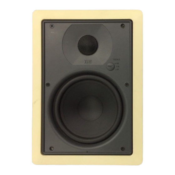
In-Wall-Lautsprecher
In-Wall LOUDSPEAKER
Wir beglückwünschen Sie zum Kauf Ihres ELAC Lautsprechers, der unter strengen Qualitäts- und
Umweltauflagen hergestellt wurde. Um die Leistung des Gerätes voll auszunutzen, lesen Sie bitte diese
Bedienungsanleitung gründlich durch. Wir raten Ihnen, diese Anleitung für späteres Nachschlagen gut
aufzubewahren.
Bitte beachten Sie, die separaten Sicherheitshinweise, die der Verpackung Ihres neuen Lautsprechers
beigepackt sind. Bitte lesen, beachten und befolgen Sie alle diese Sicherheitshinweise. Bewahren Sie diese
Sicherheitshinweise auf. Beachten Sie bitte alle Warnungen, die auf dem Gerät und in der Bedienungsanleitung
aufgeführt sind.
Congratulations on the purchase of your ELAC loudspeaker which has been designed in accordance with strict
quality and environmental requirements.
Please note the enclosed safety instructions. Please follow the instructions and keep the safety
instructions. Heed all warnings on the appliance and in the manual.
This manual will help you make the most of your home theatre system. We recommend keeping this manual in a safe
place for future reference.
Inhaltsverzeichnis

Verwandte Anleitungen für ELAC IW1030


Inhaltszusammenfassung für ELAC IW1030
- Seite 1 Sicherheitshinweise auf. Beachten Sie bitte alle Warnungen, die auf dem Gerät und in der Bedienungsanleitung aufgeführt sind. Congratulations on the purchase of your ELAC loudspeaker which has been designed in accordance with strict quality and environmental requirements. Please note the enclosed safety instructions. Please follow the instructions and keep the safety instructions.
-
Seite 3: Inhaltsverzeichnis
Inhalt / Contents Seite / page Funktion Lieferumfang Voraussetzungen Wahl des Einbauortes Kabelverlegung Vorbereitung zur Installation Installation Deinstallation Function What is included with the product Requirements Find the appropriate place for installation How to run the cables Preparations for installation Installation How to remove the front grille and the speaker unit Technische Daten / Specifications... -
Seite 4: Funktion
Funktion ELAC Wandeinbau-Lautsprecher sind ideal für den Einbau in Leichtbauwände geeignet. Der Einbaurahmen und das Abdeckgitter können lackiert werden. Die Lackierung (z.B. mit Hilfe einer Sprühdose) muss vor dem Einbau erfolgen. ELAC Wandeinbau-Lautsprecher (In-Wall-Lautsprecher) bieten hervorragenden Klang für HiFi-Stereo- oder Heimkino-Surround-Betrieb, ohne das Wohnambiente zu stören. -
Seite 5: Wahl Des Einbauortes
Wahl des optimalen Einbauortes ACHTUNG: Wählen Sie die Platzierung der In-Wall-Lautsprecher sorgfältig aus, denn ein Rückgängigmachen eines bereits getätigten Wandausschnitts ist nicht nur schwierig, sondern auch mit hohem Kosten- und Zeitaufwand verbunden. Ratschläge zur Wahl des "richtigen" Einbauortes: 1) Generell sollten Sie zu jeder Wandecke, zur Decke und zum Fußboden einen Mindestabstand von 50 cm einhalten (s. -
Seite 6: Kabelverlegung
Kabelverlegung Die ELAC In-Wall-Serie ist universell ausgelegt und kann an jeden handelsüblichen Verstärkerausgang angeschlossen werden. Das Lautsprecher-Anschlusskabel sollte in der Wand verlegt werden und ca. 35-40 cm mit offenem Ende aus der Einbauöffnung herausschauen. Verlegen Sie eine flexible Zwillingsleitung mit einem Querschnitt von 2.5mm² bei Leitungslängen bis ca. 10m und 4mm²... - Seite 7 Vorbereitung zur Installation 2) Nachdem Sie das Gitter entfernt haben, müssen Sie die sechs äußeren Schrauben mit einem Kreuzschlitz-Schraubendreher lösen. Bewahren Sie die Schrauben an einem sicheren Ort auf. Sie benötigen sie später erneut für die Montage. Achten Sie bei der Demontage (später auch bei der Montage) darauf, nicht unnötig die Lautsprechermembranen zu berühren.
-
Seite 8: Installation
Installation 1) Legen Sie die Installationsschablone so auf die Wand, dass die Kontur des Wandausschnitts auf dem Ort zu liegen kommt, wo sich später der Lautsprecher befinden soll. Achten Sie auch darauf, dass die obere und untere Kante der Schablone parallel zur Decke bzw. zum Fußboden verlaufen und dass die beiden Seitenkanten senkrecht sind. - Seite 9 Installation Der Wandausschnitt sollte dann wie nebenstehend abgebildet aussehen. Das Lautsprecher- Anschlusskabel schaut etwa 35-40 cm aus dem Ausschnitt heraus. 5) Trennen Sie die Zwillingslitze (sofern Sie eine solche verwenden) in der Mitte zwischen dem positiven und dem negativen Pol auf (s. Bild). Entfernen Sie die Isolierung der beiden Adern des Lautsprecher-Anschlusskabels mit Hilfe einer Abisolierzange.
- Seite 10 Installation 7) Nun können Sie das Gehäuse in den Wandausschnitt hineinsetzen. Achten Sie bitte darauf, dass das Gehäuse nicht drehsymmetrisch ist, dass heißt, es hat eine "obere" und eine "untere" Hälfte. Die obere ist für den Hochtöner und die untere für den Tieftöner vorgesehen. Richten Sie den Lautsprecher mit einer Wasserwaage aus.
- Seite 11 Installation 10) Das schwarze Dämm-Material sollte in der Mitte der Box sitzen und nicht zwischen Dichtung und Lautsprecher-Einheit gelangen. Nun können Sie die Lautsprecher-Einheit einsetzen. Achten Sie hierbei darauf, dass der Hochtöner "oben" und der Tieftöner "unten" sind und somit in das Gehäuse passen (s.
- Seite 12 Installation 13) Zum Abschluss setzen Sie das Gitter passgenau mit leichtem Druck ein. Das Ergebnis sollte nun in etwa so aussehen: Fertig!
-
Seite 13: Deinstallation
Deinstallation 1) Sollten Sie einmal das Gitter entfernen wollen - dies ist z.B. auch erforderlich, wenn Sie den Pegel-Wahlschalter umschalten möchten - so verwenden Sie bitte den kleinen Haken aus dem Beipack, der als Ausziehhilfe vorgesehen ist (siehe Bild). 2) Nachdem Sie das Gitter entfernt haben, müssen Sie die sechs äußeren Schrauben mit einem Kreuzschlitz-Schraubendreher lösen. -
Seite 24: Technische Daten / Specifications
Technische Daten / Specifications ELAC ELECTROACUSTIC GMBH Rendsburger Landstraße 215 24113 Kiel 02 1005 5125 660335...