Inhaltsverzeichnis
Werbung
Verfügbare Sprachen
Verfügbare Sprachen
Quicklinks
Werbung
Kapitel
Inhaltsverzeichnis

Verwandte Anleitungen für bürkert PTB 01 ATEX 2101


Inhaltszusammenfassung für bürkert PTB 01 ATEX 2101
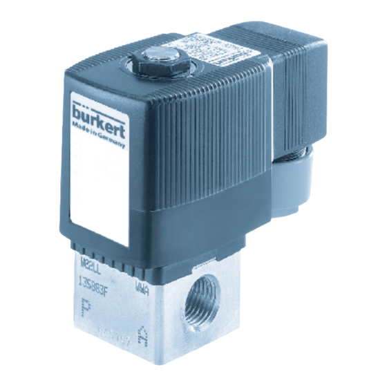
- Seite 1 Operating Instructions Bedienungsanleitung Instructions de Service PTB 01 ATEX 2101 Device with II 2 G EEx i / II 2 D Ex i -approval Example: Type 6013 Geräte mit II 2 G EEx i / II 2 D Ex i -Zulassung...
-
Seite 2: Ptb 01 Atex 2101
The markings will change as follows: PTB Ex-96.D.2010 PTB 01 ATEX 2101 EEx ia IIC T6 II 2 G EEx ia IIC T5/T6 II 2 D Ex iaD T80 °C... -
Seite 3: Inhaltsverzeichnis
Device with II 2G EEx i / II 2D Ex i - approval PTB 01 ATEX 2101 EC CONFORMITY DECLARATION ..............GENERAL INFORMATION ....................Use for intended purpose ....................... Safety information ..........................APPLICATION CONDITIONS FOR COILS ..........TECHNICAL DATA ........................ -
Seite 4: Ec Conformity Declaration
EC CONFORMITY DECLARATION As manufacturer, Bürkert Werke GmbH & Co. KG herewith declares that these products comply with the requirements of the Directives of the Committee for the Harmonization of the Legal Regulations of Member States concerning • electromagnetic compatibility (891336IEWG) •... -
Seite 5: General Information
GENERAL INFORMATION The EU type sample test certificate PTB 01 ATEX 2101 was issued by the Federal Physical-Technical Institute Bundesallee 100 38116 Braunschweig which also audits the production (CE0102). NOTE For EC Design Test Certificate PTB 01 ATEX 2101, see annex. For temperature classes and electrical data see "Technical Data". -
Seite 6: Safety Information
Safety information WARNING! • The relevant generally recognised rules for technical safety must be observed when planning the application and operation of the unit. • Suitable measures should be taken to exclude the possibility of accidental operation or impermissible interventions. •... -
Seite 7: Application Conditions For Coils
APPLICATION CONDITIONS FOR COILS 1. Operation only with associated valve The solenoid coils may only be operated with a valve body having the minimum dimensions 32 x 32 x 10 mm made of metal or plastic. A larger valve body with better thermal conductivity may be attached at any time. -
Seite 8: Technical Data
TECHNICAL DATA General information on the technical data for the unit Caution! The technical data quoted on the rating plate of the respective device must not be exceeded! CE designation PTB certification No. Example Space for barcode Ident. no / date of production Serial no. -
Seite 9: Use In Areas Of Potential Gas Explosion
Use in areas of potential gas explosion Electrical data Summary table coil size 5 and 6 Coil Length Width Height Weight Coding Con- Type of Temp. size [mm] [mm] [mm] struction ignition group class protection PD89 Diodes in coil PE28 PD93 Diodes incable head... - Seite 10 Technical function data The coils for type AC10 are available in 2 versions: 1.) Version for use with supply module 300 Ω (300 Ω barrier) 2.) Version for use with other approved supply modules (e.g. 8x remote I/O from the manufacturer STAHL). Version Resistance Minimum terminal...
-
Seite 11: Use In Areas Of Potential Dust Explosion
Use in areas of potential dust explosion Electrical data Summary table coil size 5 and 6 Coil Length Width Height Weight Coding Con- Type of max. surface size [mm] [mm] [mm] struction ignition temperature (T) protection of the coil PD89 Diodes in coil PE28... -
Seite 12: Mounting And Installation
MOUNTING AND INSTALLATION Mounting Solenoid coils Type AC10-5 are suitable for individual and block mounting. Solenoid coils Type AC10-6 are only suitable for individual mounting. NOTE With block mounting, the following valve data is to be complied with: Dimensions of the valve body: 32 mm x 32 mm x 10 mm Valve body material: brass (MS) or plastics... - Seite 13 Seal PTFE Screw in the pipe runs Pay attention to the direction of flow! Installation/Dismantling The device must not be dismantled! 01 ATEX 2101 - 11...
-
Seite 14: Installation
Installation Instrument socket Connecting cable moulded to the instrument socket and coil Always connect the earth connection! Cable connection PE28, PE30, PD89 and PD94: over a flat run by means of device connector socket type 2508 according to DIN 43650, form A PE29, PE31, PD93 and PD95: at the cast-in cable 12 - 01 ATEX 2101... -
Seite 15: Faults, Maintenance And Repairs
FAULTS, MAINTENANCE AND REPAIRS Faults In the case of faults, check: Voltage Pressure bar, psi, kPa Port connections Pipe runs 01 ATEX 2101 - 13... -
Seite 16: Maintenance And Repairs
Maintenance and repairs When operated under the conditions described in these instructions, the coils are maintenance-free. As a matter of principle, let all repairs be carried out by the manufacturer! ATTENTION! The valve must not opened during repair or maintenance work on the system, and the earth connection must not be disconnected! 14 - 01 ATEX 2101... - Seite 17 Geräte mit II 2G EEx i / II 2D Ex i -Zulassung PTB 01 ATEX 2101 EG-KONFORMITÄTSERKLÄRUNG ............ALLGEMEINE HINWEISE ................... Bestimmungsgemäße Verwendung ............... Sicherheitshinweise ......................EINSATZBEDINGUNGEN DER SPULEN .......... TECHNISCHE DATEN ....................... Allgemeine Hinweise zu den technischen Daten des Gerätes ..........................
-
Seite 18: Eg-Konformitätserklärung
EG - KONFORMITÄTSERKLÄRUNG Hiermit erklärt die Firma Bürkert Werke GmbH & Co. KG als Hersteller, dass diese Erzeugnisse den Anforderungen entsprechen, die in den Richtlinien des Rates zur An- gleichung der Rechtsvorschriften der Mitgliedstaaten über • die elektromagnetische Verträglichkeit (891336IEWG) •... -
Seite 19: Allgemeine Hinweise
Bundesallee 100 38116 Braunschweig ausgestellt, die auch die Fertigung auditiert (CE0102). HINWEIS Die Baumusterprüfbescheinigung PTB 01 ATEX 2101 finden Sie im Anhang. Temperaturklassen und elektrische Daten siehe "Tech- nische Daten". Bestimmungsgemäße Verwendung Bitte beachten Sie die Hinweise dieser Betriebsanleitung, die unterschiedlichen Einsatzbedingungen und zulässigen Daten gemäß... -
Seite 20: Sicherheitshinweise
Sicherheitshinweise ACHTUNG! • Halten Sie sich bei Einsatzplanung und Betrieb des Gerätes an die einschlägigen allgemein anerkannten sicherheitstechnischen Regeln. • Treffen Sie geeignete Maßnahmen, um unbeabsichtigtes Betätigen oder unzulässige Beeinträchtigungen auszuschließen. • Das Ventil darf nicht demontiert werden ! • Beachten Sie, dass in Systemen, die unter Druck stehen, Leitungen und Ventile nicht gelöst werden dürfen. -
Seite 21: Einsatzbedingungen Der Spulen
EINSATZBEDINGUNGEN DER SPULEN 1. Betrieb nur mit zugehörigem Ventil Die Magnetspulen dürfen nur mit einem Ventilkörper mit Mindestabmessungen 32 x 32 x10 mm aus Metall oder Kunststoff betrieben werden. Ein größerer Ventilkörper mit besserer Wärmeleitfähigkeit darf jederzeit angebaut werden. 2. Einzelmontage / Blockmontage Die Magnetspulen Typ AC10- 5 - sind für Einzel- und Blockmontage geeignet. -
Seite 22: Technische Daten
TECHNISCHE DATEN Allgemeine Hinweise zu den technischen Daten des Gerätes ACHTUNG! Die auf dem Typschild des jeweiligen Gerätes angegebenen technischen Daten dürfen nicht überschritten werden! CE-Kennzeichnung PTB-Zulassungsnummer der Magnetspule Beispiel Platz für Barcode Ident-Nr. der Spule - Herstelldaten Serien-Nr. der Spule Umgebungstemperatur Spannung (±10 %) - Leistung Spulentyp - Anschlussgröße für... -
Seite 23: Einsatz In Gasexplosionsgefährdeten Bereichen
Einsatz in gasexplosionsgefährdeten Bereichen Elektrische Daten Tabellarische Übersicht Spulengröße 5 und 6 Spulen- Länge Breite Höhe Masse Verschlüs-- Aufbau Zünd- Gas- Temp.- größe (mm) (mm) (mm) selung schutzart gruppe Klasse PD89 Dioden in der Spule PE28 Dioden in PD93 der Geräte- PE29 steckdose EEx ia... -
Seite 24: Zulässiger Umgebungstemperaturbereich
Funktionstechnische Daten Die Spulen des Typs AC 10 sind in 2 Versionen lieferbar: 1.) Version für Einsatz mit Versorgungsbaustein 300 Ω (300 Ω Barriere) 2.) Version für Einsatz mit anderen zugelassenen Versorgungsbausteinen (z.B. 8-fach Remote I/O der Fa. STAHL) Version Widerstand Mindestklemm- Mindest-... -
Seite 25: Einsatz In Staubexplosionsgefährdeten Bereichen
Einsatz in staubexplosionsgefährdeten Bereichen Elektrische Daten Tabellarische Übersicht Spulengröße 5 und 6 Spulen- Länge Breite Höhe Masse Verschlüs-- Aufbau Zünd- max. Oberfläch- größe (mm) (mm) (mm) selung schutzart entemperatur (T) der Spule PD89 Dioden in der Spule PE28 Dioden in PD93 der Geräte- PE29... -
Seite 26: Montage Und Installation
MONTAGE UND INSTALLATION Montage Die Magnetspulen Typ AC10-5- sind für Einzel- und Blockmontage geeignet. Die Magnetspulen Typ AC10-6- eignen sich nur für Einzelmontage. HINWEIS Bei Blockmontage sind folgende Daten der Ventile einzuhalten: Abmessungen des Ventilkörpers: 32 mm x 32 mm x 10 mm Werkstoff des Ventilkörpers: Messing (MS) oder Kunststoff (PA 6 GV) - Seite 27 Abdichtung PTFE Einschrauben der Rohrleitungen beachten! Durchflussrichtung Montage/Demontage Das Gerät darf nicht demontiert werden! 01 ATEX 2101 - 25...
-
Seite 28: Installation
Installation Gerätesteckdose Anschlusskabel mit Gerätesteckdose und Spule vergossen Schutzleiter immer anschließen! Leitungsanschluss PE28, PE30, PD89 und PD94: über Flachstecker mittels Gerätesteckdose Typ 2508 nach DIN 43650, Form A PE29, PE31, PD93 und PD95: am eingegossenen Kabel 26 - 01 ATEX 2101... -
Seite 29: Störungen, Wartung Und Reparaturen
STÖRUNGEN, WARTUNG UND REPARATUREN Störungen Prüfen Sie bei Störungen: Spannung Druck bar, psi, kPa Leitungsanschlüsse Rohrleitungen 01 ATEX 2101 - 27... -
Seite 30: Wartung Und Reparaturen
Wartung und Reparaturen Die Spulen sind beim Betrieb unter den in dieser Anleitung beschriebenen Bedin- gungen wartungsfrei. Lassen Sie Reparaturen grundsätzlich vom Hersteller durchführen! ACHTUNG! Bei Reparatur- oder Wartungsarbeiten an der Anlage darf das Ventil nicht geöffnet und die Schutzleiterverbindung nicht getrennt werden! 28 - 01 ATEX 2101... - Seite 31 Appareil avec mode de protection II 2G EEx i / II 2D Ex i PTB 01 ATEX 2101 DÉCLARATION CE DE CONFORMITÉ ..........RECOMMANDATIONS GENERALES ............Utilisation conforme .......................... Consignes sécurité ..........................CONDITIONS D’UTILISATION DES BOBINES ......CARACTERISTIQUES TECHNIQUES .............
-
Seite 32: Déclaration Ce De Conformité
DÉCLARATION CE DE CONFORMITÉ Par la présente, le fabricant, la société Bürkert Werke GmbH & Co. KG déclare que le produit satisfait les exigences de la directive du conseil pour le rapprochement des législations des Etats membres concernant • la compatibilité électromagnétique (891336IEWG) •... -
Seite 33: Recommandations Generales
RECOMMANDATIONS GENERALES L’attestation d’examen CE de type PTB 01 ATEX 2101 a été établie par l’Institut physico-technique fédéral Bundesallee 100 38116 Braunschweig qui a également passé en revue la fabrication (CE0102). REMARQUE Certificat d’essai de modèle CE PTB 01 ATEX 2101, voir annexe. -
Seite 34: Consignes Sécurité
Consignes générales de sécurité ATTENTION! • Lors de la planification d’utilisation et l’exploitation de l’appareil, s’en tenir aux règles de la technique généralement reconnues. • Prendre les mesures appropriées afin d’éviter tout actionnement involontaire ou emploi abusif. • Le démontage de l’électrovanne est prohibé! •... -
Seite 35: Conditions D'utilisation Des Bobines
CONDITIONS D’UTILISATION DES BOBINES 1. Utilisable uniquement avec la vanne correspondante Les bobines magnétiques ne doivent être mises en service qu'avec des corps de vanne ayant les cotes minimales 32 x 32 x10 mm en métal ou plastique. Un corps de vanne de plus grande dimension avec une meilleure conductibilité thermique peut toujours être annexé... -
Seite 36: Caracteristiques Techniques
CARACTERISTIQUES TECHNIQUES Informations générales concernant les caractéristiques techniques de l’appareil ATTENTION! Les caractéristiques techniques figurant sur la plaquette signalétique de l’appareil ne doivent en aucun cas être dépassées! Identification CE No. d'agrément PTB Exemple Place pour Code No. d'identification - date de production N°... -
Seite 37: Emploi Dans Des Zones Exposées À Des Explosions De Gaz
Emploi dans des zones exposées aux explosions de Caractéristiques électriques Tableau sommaire des tailles de bobine 5 et 6 Taille Longueur Largeur Hauteur Poids Code Montage Mode de Groupe Classe bobine [mm] [mm] [mm] protection de gaz de temp. PD89 Diode dans la bobine PE28 PD93 Diode dans... - Seite 38 Caractéristiques techniques de fonctionnement Les bobines du type AC 10 sont disponibles en 2 versions: 1. Version pour emploi avec module d’alimentation 300 Ω (barrière 300 Ω) 2. Version pour emploi avec d’autres modules d’alimentation admis (p.ex. Remote I/O octuple de la maison STAHL) Version Résistance Tension minimale...
-
Seite 39: Emploi Dans Des Zones Exposées À Des Coups De Poussière
Emploi dans des zones exposées aux coups de poussière Caractéristiques électriques Tableau sommaire des tailles de bobine 5 et 6 Taille Longueur Largeur Hauteur Poids Code Montage Mode de Température bobine [mm] [mm] [mm] protection superficielle max. (T) de la bobine PD89 Diode dans la bobine PE28... -
Seite 40: Montage Et Installation
MONTAGE ET INSTALLATION Montage Les bobines magnétiques, type AC10-5 sont prévues pour le montage isolé et en bloc Les bobines magnétiques, type AC10-6 sont prévues uniquement pour la montage isolé. REMARQUE Dans le cas du montage en bloc, respecter les données suivante de la vanne: Dimensions du corps de la vanne: 32 mm x 32 mm x 10 mm Matière de la vanne:... - Seite 41 Etanchéité PTFE Visser la tuyauterie Observer le sens d'écoulement! Montage/Démontage Le démontage de l'appareil est prohibé! 01 ATEX 2101 - 39...
-
Seite 42: Installation
Installation Prise d'appareil Câble de raccordement scellé avec prise et bobine Toujours connecter le conducteur de protection! Raccordement de ligne PE28, PE30, PD89 et PD94 sur trajet plat au moyen de la prise de l’appareil, type 2508 selon DIN 43650, forme A PE29, PE31, PD93 et PD95 au câble scellé... -
Seite 43: Derangements, Maintenance Et Reparations
DERANGEMENTS, MAINTENANCE ET REPARATIONS Dérangements En cas de panne, vérifier les points suivants: Tension Pression bar, psi, kPa Raccordements Tuyauterie 01 ATEX 2101 - 41... -
Seite 44: Maintenance Et Réparation
Maintenance et réparation En service dans les conditions énoncées das ces instructions, les bobines ne nécessitent aucune maintenance. D'une maière générale, confier les réparations éventuelles au fabricant! ATTENTION! Lors d'interventions de réparation ou de maintenance, la vanne ne doit pas être ouverte, et la connexion du conducteur de protection ne doit pas être séparée! 42 - 01 ATEX 2101... -
Seite 45: Certificat D'essai De Modèle Ce
Annex / Anhang / Annexe PTB 01 ATEX 2101 EC DESIGN TEST CERTIFICATE ..............EG-BAUMUSTERPRÜFBESCHEINIGUNG ........CERTIFICAT D’ESSAI DE MODÈLE CE ..........01 ATEX 2101 - 43... - Seite 46 44 - 01 ATEX 2101...
- Seite 47 01 ATEX 2101 - 45...
- Seite 48 46 - 01 ATEX 2101...
- Seite 49 01 ATEX 2101 - 47...
- Seite 50 48 - 01 ATEX 2101...
- Seite 51 01 ATEX 2101 - 49...
- Seite 52 50 - 01 ATEX 2101...
- Seite 53 01 ATEX 2101 - 51...
- Seite 54 52 - 01 ATEX 2101...
- Seite 55 01 ATEX 2101 - 53...
- Seite 56 54 - 01 ATEX 2101...
- Seite 57 01 ATEX 2101 - 55...
- Seite 58 56 - 01 ATEX 2101...
- Seite 59 01 ATEX 2101 - 57...
- Seite 60 58 - 01 ATEX 2101...
- Seite 62 Addresses of BC offices/Adressliste BC Länder Europe/Europa BC-A Austria, Österreich Bürkert-Contromatic G.m.b.H. BC-NL Netherlands, Niederlande Diefenbachgasse 1-3 Bürkert Contromatic BV A-1150 Wien Computerweg 9 Phone: Int.(+43 1)894 13 33, Nat.(01)894 13 33 NL-3542 DP Utrecht Fax: Int.(+43 1)894 13 00, Nat.(01)894 13 00 Phone: Int.(+31 346)58 10 10,Nat.(0346)58 10 10 E-mail: info@buerkert.at Fax:...
- Seite 63 Addresses of BC offices/Adressliste BC Länder APAC Suzhou BC-AUS Australia, Australien Burkert Contromatic (Shanghai), Co., Ltd. BURKERT CONTROMATIC AUSTRALIA PTY. LTD Room 5, #06-06 2 Welder Road Block A, No. 5 Xinghan Street Seven Hills, NSW 2147 SIP Suzhou P. R. China, 215021 AUSTRALIA Phone: Int.(+86512)67611916, Nat.
- Seite 64 Addresses of BC offices/Adressliste BC Länder APAC BC-RP Philippines, Philippinen BC-RC Taiwan, Taiwan BURKERT CONTROMATIC PHILIPPINES, INC. Burkert Contromatic Taiwan Ltd. 8467, West Service Road Km 14 9 F, No. 32, Chenggong Road, Sec. 1, South Superhighway, Sunvalley Nangang District Paranaque City, Metro Manila Taipei PHILIPPINES...
- Seite 65 Adressliste Bürkert Fluid Control Systems Deutschland Headquarter and Service Center, Stammsitz und Service-Center Ingelfingen Bürkert GmbH & Co. KG Christian-Bürkert-Straße 13 - 17 DE-74653 Ingelfingen Telefon: Int. (+497940)10-111, Nat. (07940)10-111 Fax: Int. (+497940)10-448, Nat. (07940)10-448 E-mail: info@de.buerkert.com Distribution Center, Vertriebs-Center Service-Center, Dienstleistungs-Center Dortmund Berlin...
- Seite 68 The smart choice of Fluid Control Systems www.buerkert.com...