Inhaltsverzeichnis
Werbung
Verfügbare Sprachen
Verfügbare Sprachen
Quicklinks
Werbung
Kapitel
Inhaltsverzeichnis

Verwandte Anleitungen für Siemens KE6000-8AH/CC


Inhaltszusammenfassung für Siemens KE6000-8AH/CC
- Seite 1 7KE6000-8AH /CC 7KE6000-8AJ /CC Betriebsanleitung/Operating Instructions Bestell-Nr./Order No.: E50417-K1074-C295-A1 Hinweise für den Einsatz Deutsch: Seite 3 Sync-LWL-Verteiler Directions for use English: page 21 Sync-FO-Multiplexer Copyright Siemens AG 2003...
- Seite 2 Subject to change without prior notice. Release: 1.00.03 tered trademarks of SIEMENS AG. All other product and brand names in these operating instructions might be trademarks, the use of which by third persons for their purposes might infringe the rights of their respective owners.
-
Seite 3: Inhaltsverzeichnis
Sync-LWL-Verteiler Deutsch Inhalt Angaben zur Konformität ....................4 Hinweise und Warnungen ....................5 Allgemeine Hinweise ......................7 Aus- und Einpacken des Gerätes ..................8 Lagerung ..........................8 Verwendung ........................9 Merkmale ........................... 9 Funktion ........................... 10 Anschlüsse ........................11 Anschlusshinweise ......................12 Montage ........................... -
Seite 4: Angaben Zur Konformität
Betriebsmittel zur Verwendung innerhalb bestimmter Spannungsgrenzen (Niederspan- nungsrichtlinie 73/23/EWG). Diese Konformität ist das Ergebnis einer Prüfung, die durch die Siemens AG gemäß Artikel 10 der Richtlinie in Übereinstimmung mit den Fachgrundnormen EN 61000-6-4 und EN 61000-6-2 für die EMV-Richtlinie und der Norm EN 61010-1 für die Niederspannungs- richtlinie durchgeführt worden ist. -
Seite 5: Hinweise Und Warnungen
Sync-LWL-Verteiler Deutsch Hinweise und Warnungen Die Hinweise und Warnungen in dieser Betriebsanleitung sind zu Ihrer Sicherheit und einer angemessenen Lebensdauer des Gerätes zu beachten. Folgende Signalbegriffe und Standarddefinitionen werden dabei verwendet: GEFAHR bedeutet, dass Tod, schwere Körperverletzung oder erheblicher Sach- schaden eintreten wird, wenn die entsprechenden Vorsichtsmaßnah- men nicht getroffen werden. - Seite 6 Deutsch Sync-LWL-Verteiler WARNUNG Beim Betrieb elektrischer Geräte stehen zwangsläufig bestimmte Teile dieser Geräte unter gefährlicher Spannung. Nichtbeachtung kann Tod, Körperverletzung oder erheblichen Sach- schaden zur Folge haben. Nur entsprechend qualifiziertes Personal soll an diesem Gerät oder in dessen Nähe arbeiten. Dieses muss gründlich mit allen Warnungen und Instandhaltungsmaßnahmen gemäß...
-
Seite 7: Allgemeine Hinweise
Instandhaltung berücksichtigen. Sollten Sie weitere Informationen wünschen, oder sollten besondere Probleme auftreten, die in dieser Unterlage nicht ausführlich genug behandelt werden, dann fordern Sie bitte die benötigte Auskunft von Ihrer örtlichen Siemens-Nieder- lassung an, oder wenden Sie sich direkt an unsere Kontaktadresse (siehe Seite 40). -
Seite 8: Aus- Und Einpacken Des Gerätes
Deutsch Sync-LWL-Verteiler Aus- und Einpacken des Gerätes Die Geräte werden im Werk so verpackt, dass sie die Anforderungen nach IEC 60255-21 erfüllen. Das Aus- und Einpacken ist mit der üblichen Sorgfalt ohne Gewaltanwendung und nur unter Verwendung von geeignetem Werkzeug vorzunehmen. Die Geräte sind durch Sichtkontrolle auf einwandfreien mechanischen Zustand zu überprüfen. -
Seite 9: Verwendung
Sync-LWL-Verteiler Deutsch Verwendung Der Sync-LWL-Verteiler dient zum Umsetzen und Verteilen eines digitalen Signals in Lichtwellenleiter-Signale. Der Eingangspegel des Sync-LWL-Verteilers beträgt 24 V. Das Eingangssignal wird parallel auf 8 LWL-Ausgangskanäle verteilt. Er findet Anwendung in der Umsetzung und Übertragung von Signalen zur Synchronisation der Echtzeituhr im SIMEAS R. -
Seite 10: Funktion
Deutsch Sync-LWL-Verteiler Funktion Bild 1 Blockschaltbild des Sync-LWL-Verteilers Abbildung 1 zeigt die Funktionsweise des Sync-LWL-Verteilers. E50417-K1074-C295-A1... -
Seite 11: Anschlüsse
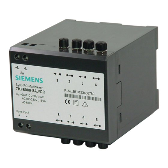
Sync-LWL-Verteiler Deutsch Anschlüsse Bild 2 Belegung der Anschlussklemmen Versorgungsspannung Hilfsenergie gemäß Bestellvariante (siehe Seite 19) Elektrischer Sync-Input Sync-Input + Signaleingang (plus) Sync-Input - Signaleingang (minus) LWL-Ausgänge E50417-K1074-C295-A1... -
Seite 12: Anschlusshinweise
Deutsch Sync-LWL-Verteiler Anschlusshinweise Hilfsenergieanschluss und Signaleingang Direktanschluss: Massivleiter oder Litzenleiter mit Aderendhülse für Leitungsquerschnitte von 0,5 mm bis 2,5 mm (entsprechend AWG 12 bis 22). Die Spannungsfestigkeit der Anschlussleitungen (Hilfsenergieanschluss und Signaleingang) muss min. 300 V AC betra- gen. Drehmoment: min 0,5 Nm. Der maximale Nennstrom des Gerätes beträgt 0,5 A. -
Seite 13: Montage
Sync-LWL-Verteiler Deutsch Montage Warnung Beim Betrieb elektrischer Geräte stehen zwangsläufig bestimmte Teile dieser Geräte unter gefährlicher Spannung. Bei Nichtbeachtung der Bedienhinweise können deshalb schwere Körperverletzungen oder Sachschäden auftreten. Montage und elektrischer Anschluss des Geräts sollten nur durch ent- sprechend qualifiziertes Personal vorgenommen werden. Insbesondere müssen alle Warnhinweise unbedingt beachtet werden. -
Seite 14: Inbetriebsetzung
Deutsch Sync-LWL-Verteiler Inbetriebsetzung Prüfen Sie, ob die Betriebsdaten mit den Werten auf dem Typenschild übereinstimmen. Nehmen Sie am Sync-LWL-Verteiler keine Veränderungen vor. Schnappen Sie den Sync-LWL-Verteiler mittels der Gehäuseschnappbefestigung auf eine Hutschiene auf. Schließen Sie das Sync-Signal an die Klemmen “Sync-Input +” und “Sync-Input -” an. Schließen Sie die LWL-Kanäle an den Sendedioden mittels F-SMA (Schraubver- bindung) an. -
Seite 15: Technische Daten
Sync-LWL-Verteiler Deutsch Technische Daten Hilfsenergie U Nenneingangsspannung U - Gleichspannung 24 … 60 V DC; 110 … 250 V DC - Wechselspannung 100 … 230 V AC; 45 … 65 Hz Eingangsbereich - Gleichspannung ±20% - Wechselspannung ±20% Leistungsaufnahme - Gleichspannung - Wechselspannung 16 VA vorzuschaltende Sicherung... - Seite 16 Deutsch Sync-LWL-Verteiler Sicherheit nach IEC/EN 61010, Teil 1 (VDE 0411 Teil 1) Überspannungskategorie Verschmutzungsgrad Brandbeständigkeitsklasse des Gehäuses V0 nach UL94 Spannungsprüfungen (Typprüfung) Signalausgang gegen Hilfsspannung U = 5,2 kV DC/1 min Stoßspannung nach IEC 60255-5 (Typprüfung) 5 kV Spannungsprüfung (Stückprüfung) Signalausgang gegen Hilfsspannung U = 3,1 kV DC/2 s Schutzart:...
- Seite 17 Sync-LWL-Verteiler Deutsch Mechanische Prüfungen Schwing- und Schockbeanspruchung IEC 60255-21 und IEC 60068 bei stationärem Einsatz - Schwingung IEC 60255-21-1, Klasse 2, IEC 60068-2-6 - Schock IEC 60255-21-2, Klasse 1, IEC 60068-2-27 - Schwingung bei Erdbeben IEC 60255-21-3, Klasse 1, IEC 60068-3-3 Schwing- und Schockbeanspruchung IEC 60255-21 und IEC 60068-2 beim Transport...
-
Seite 18: Maßbilder
Deutsch Sync-LWL-Verteiler Maßbilder Bild 3 Maßbilder des Sync-LWL-Verteiler E50417-K1074-C295-A1... -
Seite 19: Bestellhinweise
Sync-LWL-Verteiler Deutsch Bestellhinweise Benennung Bestellnummer Kurzangabe Sync-LWL-Verteiler – Hilfsenergie DC 24 … 60 V DC 110 … 250 V AC 100 … 230; 45 … 65 Hz Wartung, Instandsetzung und Reinigung Die Geräte 7KE6000 bedürfen keiner besonderen Wartung. Sie können bei Bedarf in einem Labor geprüft werden. - Seite 20 Deutsch Sync-LWL-Verteiler E50417-K1074-C295-A1...
- Seite 21 Sync-FO-Multiplexer English Contents Statement of Conformity ....................22 Hints and Warnings ......................23 General Remarks ......................25 Unpacking and Repacking ....................26 Storage ..........................26 Range of Application ......................27 Characteristics ......................... 27 Function ........................... 28 Connections ........................29 Connection Hints ......................30 Mounting ..........................
-
Seite 22: Statement Of Conformity
(EMC Council Directive 89/336/EEC) and concerning electrical equipment for use within specified voltage limits (Low-voltage directive 73/23 EEC). This conformity is proved by tests conducted by Siemens AG in accordance with Article 10 of the Council Directive in agreement with the generic standards EN 61000-6-4 and EN 61000-6-2 for EMC directive, and with the standard EN 61010-1 for the low-voltage directive. -
Seite 23: Hints And Warnings
Sync-FO-Multiplexer English Hints and Warnings The warnings and notes contained in these operating instructions serve for your own safety and for an appropriate lifetime of the device. Please observe them! The following indicators and standard definitions are used: DANGER indicates that death, severe personal injury or substantial property damage will result if proper precautions are not taken. - Seite 24 English Sync-FO-Multiplexer Warning During operation of electrical equipment, certain parts of this device are subject to dangerous voltages. Severe personal injury or significant equipment damage could result from improper behaviour. Only qualified personnel should work on this equipment or in the vicinity of this equipment.
-
Seite 25: General Remarks
Siemens subsidiary or from our contact address (refer to page 40). Furthermore, the contents of this operating instructions are not part of an earlier or existing agreement, consent, or a legal regulation and do not represent a modification of any of these. -
Seite 26: Unpacking And Repacking
English Sync-FO-Multiplexer Unpacking and Repacking When dispatched from the factory, the equipment is packed in accordance with the guide- lines laid down in IEC 60255-21. Unpack and pack them with appropriate care and without using force, using only suitable tools. Inspect the devices and verify that they are in proper mechanical condition. Note any further instructions which may be enclosed. -
Seite 27: Range Of Application
Sync-FO-Multiplexer English Range of Application The Sync-FO-Multiplexer converts a digital signal into fibre-optic signals. The electrical input level is 24 V. The input signal is distributed to the 8 FO output channels in parallel. It is used to convert and transmit signals for the synchronization of the SIMEAS R real-time clock. -
Seite 28: Function
English Sync-FO-Multiplexer Function Sync-FO-Multiplexer Figure 4 Block diagram of the Figure 4 shows the block diagram of the Sync-FO-Multiplexer. E50417-K1074-C295-A1... -
Seite 29: Connections
Sync-FO-Multiplexer English Connections Figure 5 Connection terminals Power supply Auxiliary voltage according to the ordering data (refer to page 37) Electrical Sync-Input Sync + Signal input (plus) Sync - Signal input (minus) Optical outputs E50417-K1074-C295-A1... -
Seite 30: Connection Hints
English Sync-FO-Multiplexer Connection Hints Auxiliary Voltage and Signal Input Direct Cable Connection: Solid or stranded conductor with connector sleeve for conductor cross-sections from 0.5 mm to 2.5 mm , corresponding to AWG 12 to 22. The rated voltage of the connecting cables (auxiliary voltage and signal input) must be at least 300 V AC. Tightening Torque: min 0.5 Nm The maximum rated current of the device is 0.5 A. -
Seite 31: Mounting
Sync-FO-Multiplexer English Mounting Warning When operating electrical devices, certain parts of these devices are subject to dangerous voltages. Therefore, noncompliance with the safe- ty notices may cause severe bodily injury or property damage. Only adequately qualified personnel may mount and connect the de- vice. -
Seite 32: Commissioning
English Sync-FO-Multiplexer Commissioning Check if the operating data correspond to the values stated on the rating plate. Do not modify the Sync-FO-Multiplexer in any way. Snap the mounting device of the Sync-FO-Multiplexer onto a DIN rail. Connect the Sync signal to terminals “Sync-Input +” and “Sync-Input -”. Connect the FO channels to the send diodes using the F-SMA screw-type terminals. -
Seite 33: Technical Data
Sync-FO-Multiplexer English Technical Data Auxiliary voltage V Rated input voltage V - DC voltage 24 … 60 V DC; 110 … 250 V DC - AC voltage 100, 115 … 230 V AC; 45 … 65 Hz Input range - DC voltage ±20% - AC voltage ±20%... - Seite 34 English Sync-FO-Multiplexer Safety according IEC/EN 61010, part 1 (VDE 0411 part 1) Overvoltage category Pollution degree Fire resistance class of housing V0 according to UL94 Voltage test (type test) Signal output vs. power supply U = 5.2 kV DC/1 min Impulse voltage according to IEC 60255-5 (type test) 5 kV Voltage test (routine test)
- Seite 35 Sync-FO-Multiplexer English Mechanical Tests Vibration and shock test IEC 60255-21 and IEC 60068 During operation - Vibration IEC 60255-21-1, class 2, IEC 60068-2-6 - Shock IEC 60255-21-2, class 1, IEC 60068-2-27 - Seismic vibration IEC 60255-21-3, class 1, IEC 60068-3-3 Vibration and shock test IEC 60255-21 and IEC 60068-2 During transport...
-
Seite 36: Dimensions
English Sync-FO-Multiplexer Dimensions Figure 6 Dimension drawings of the Sync-FO-Multiplexer E50417-K1074-C295-A1... -
Seite 37: Ordering Information
Sync-FO-Multiplexer English Ordering Information Item Order number Short form Sync-FO-Multiplexer – ¦ Auxiliary voltage DC 24 … 60 V DC 110 … 250 V AC 100 … 230; 45 … 65 Hz Maintenance, Repair and Cleaning The devices 7KE6000 do not require special maintenance. If necessary, they can be checked in a laboratory. - Seite 38 English Sync-FO-Multiplexer E50417-K1074-C295-A1...
- Seite 39 Sync-LWL-Verteiler Sync-FO-Multiplexer E50417-K1074-C295-A1...
-
Seite 40: Kontaktadresse
Kontaktadresse Contact Address SIEMENS AG Power Transmission and Distribution Power Automation Postfach 4806 D-90026 Nürnberg Germany Hotline: Tel.: +49 180 524 7000 Fax: +49 180 524 2471 eMail: support@ptd.siemens.de Internet: http://www.powerquality.de Weitergabe sowie Vervielfältigung dieser Unterlage, Ver- wertung und Mitteilung ihres Inhalts nicht gestattet, soweit nicht ausdrücklich zugestanden.