Herunterladen Diese Seite drucken
Balluff BTL7-P511-M -P-S32 Serie Betriebsanleitung

Balluff BTL7-P511-M -P-S32 Serie Betriebsanleitung

Vorschau ausblenden Andere Handbücher für BTL7-P511-M -P-S32 Serie:

Werbung

Verfügbare Sprachen
  • DE

Verfügbare Sprachen

  • DEUTSCH, seite 1
BTL7-P511 -M _ _ _ _ -P-S32/S115/KA_ _
Betriebsanleitung
deutsch

Werbung

loading

Inhaltszusammenfassung für Balluff BTL7-P511-M -P-S32 Serie

  • Seite 1 BTL7-P511 -M _ _ _ _ -P-S32/S115/KA_ _ Betriebsanleitung deutsch...
  • Seite 2 www.balluff.com...
  • Seite 3 Elektrischer Anschluss 4.4.1 Steckverbinder S32/Kabel 4.4.2 Steckverbinder S115 Schirmung und Kabelverlegung Inbetriebnahme System in Betrieb nehmen Hinweise zum Betrieb P-Schnittstelle Prinzip DPI/IP-Verfahren 6.2.1 Funktion und Eigenschaften 6.2.2 Protokollparameter Technische Daten Genauigkeit Umgebungsbedingungen Spannungsversorgung Ausgang Maße, Gewichte Verbindung zur Auswerteeinheit www.balluff.com deutsch...
  • Seite 4 BTL7-P511 -M _ _ _ _ -P-S32/S115/KA_ _ Micropulse Wegaufnehmer im Profilgehäuse Zubehör Geführte Positionsgeber Gelenkstange BTL2-GS10-_ _ _ _-A Freie Positionsgeber Steckverbinder und Kabel 8.4.1 BKS-S32/S33M-00, frei konfektionierbar 8.4.2 BKS-S232/S233-PU-_ _, konfektioniert 8.4.3 BKS-S115/S116-PU-_ _, konfektioniert Typenschlüssel Anhang 10.1 Umrechnung Längeneinheiten 10.2 Typenschild deutsch...
  • Seite 5 Zulassungen und Normen sind in der Konformitätserklärung aufgeführt. Die Positionsgeber sind in unterschiedlichen Bauformen lieferbar und deshalb gesondert zu bestellen. Zulassungen und Kennzeichnungen UL-Zulassung File No. E227256 US-Patent 5 923 164 Das US-Patent wurde in Verbindung mit diesem Produkt erteilt. www.balluff.com deutsch...
  • Seite 6 Vermeidung von Gefahren. Anlage eingebaut. Die einwandfreie Funktion gemäß den Angaben in den technischen Daten wird nur mit original Die verwendeten Warnhinweise enthalten verschiedene BALLUFF-Zubehör zugesichert, die Verwendung anderer Signalwörter und sind nach folgendem Schema aufgebaut: Komponenten bewirkt Haftungsausschluss. SIGNALWORT Das Öffnen des Wegaufnehmers oder eine nicht bestim-...
  • Seite 7 Positionsgeber: Definiert die zu messende Position auf dem Wellenleiter. Positionsgeber sind in unterschiedlichen Bauformen lieferbar und gesondert zu bestellen (siehe Zubehör ab Seite 18). Nennlänge: Um den Wegaufnehmer optimal an die Anwendung anzupassen, sind Nennlängen von 50 mm bis 7620 mm lieferbar. www.balluff.com deutsch...
  • Seite 8 
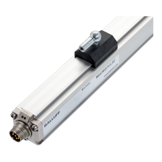
BTL7-P511 -M _ _ _ _ -P-S32/S115/KA_ _ Micropulse Wegaufnehmer im Profilgehäuse Aufbau und Funktion (Fortsetzung) Funktion LED Anzeige Im Wegaufnehmer BTL7 befindet sich der Wellenleiter, LED 1 LED 2 geschützt durch ein Aluminiumgehäuse. Entlang des Wellenleiters wird ein Positionsgeber bewegt. Dieser Positionsgeber ist mit dem Anlagenbauteil verbunden, des- sen Position bestimmt werden soll.
  • Seite 9 (siehe Bild 4-4 bis Bild 4-8) als auch für geführte Positionsgeber (siehe Bild 4-1 bis Bild 4-3). Bild 4-3: Maße und Abstände mit Positionsgeber BTL5-M/N-2814-1S BTL5-M-2814-1S BTL5-N-2814-1S Abstand X 48,5 mm 57 mm Abstand Y 51 mm 59,5 mm Tab. 4-1: Abstände für Positionsgeber BTL5-M/N-2814-1S www.balluff.com deutsch...
  • Seite 10 BTL7-P511 -M _ _ _ _ -P-S32/S115/KA_ _ Micropulse Wegaufnehmer im Profilgehäuse Einbau und Anschluss (Fortsetzung) Freie Positionsgeber Beim Einbau des Positionsgebers ist zu beachten: – Um die Genauigkeit des Wegmesssystems zu gewähr- leisten, wird der Positionsgeber mit nichtmagnetisier- baren Schrauben (Edelstahl, Messing, Aluminium) am bewegten Maschinenteil befestigt.
  • Seite 11 BU Blau 10…30 V BN Braun nicht belegt WH Weiß Nicht belegte Adern können steuerungsseitig mit GND verbunden werden, aber nicht mit dem Schirm. Tab. 4-3: Anschlussbelegung Bild 4-9: Pinbelegung S32 (Draufsicht auf Stecker am Wegaufneh- mer), 8-poliger Rundstecker M16 www.balluff.com deutsch...
  • Seite 12 BTL7-P511 -M _ _ _ _ -P-S32/S115/KA_ _ Micropulse Wegaufnehmer im Profilgehäuse Einbau und Anschluss (Fortsetzung) Schirmung und Kabelverlegung Definierte Erdung! Wegaufnehmer und Schaltschrank müssen auf dem gleichen Erdungspotenzial liegen. Schirmung Zur Gewährleistung der elektromagnetischen Verträglich- keit (EMV) sind folgende Hinweise zu beachten: –...
  • Seite 13 Reparatur durch den Hersteller die korrekten Werte prüfen. Hinweise zum Betrieb – Funktion des Wegmesssystems und aller damit ver- bundenen Komponenten regelmäßig überprüfen. – Bei Funktionsstörungen das Wegmesssystem außer Betrieb nehmen. – Anlage gegen unbefugte Benutzung sichern. www.balluff.com deutsch...
  • Seite 14 BTL7-P511 -M _ _ _ _ -P-S32/S115/KA_ _ Micropulse Wegaufnehmer im Profilgehäuse P-Schnittstelle Prinzip Betrieb mit IP-Datenprotokoll Wird die Länge des Init-Impulses T auf 10 μs bis 50 μs Die P-Schnittstelle ist eine universelle Impuls-Schnittstelle vergrößert, schaltet der Wegaufnehmer vom DPI-Messbe- und vereint die Funktionen der fallenden und steigenden trieb auf den Betrieb mit dem IP-Datenprotokoll um (siehe Flanken.
  • Seite 15 Anfrage Antwort D0…Dn Herstellerkennung Vendor name ASCII coded 'B' 'A' 'L' 'L' 'U' 'F' 'F' oder 06h Vendor code Hex coded 0x00000001 for BALLUFF Typschlüssel Type key ASCII coded Beispiel: 'BTL7-P511-M0500-P-S32' Seriennummer Serial number ASCII coded Beispiel: '15011400012345 DE' oder 07h...
  • Seite 16 Gradient (normiert) 8,9122807 µs/inch 2000 m über Meeresspiegel. max. erfassbare Geschwindigkeit 10 m/s Einzelbestimmung nach Balluff-Werknorm, Resonanzen ausgenommen Für : Der Wegaufnehmer muss extern über einen energiebegrenzten Stromkreis gemäß UL 61010-1 oder eine Stromquelle begrenzter Leistung Umgebungsbedingungen gemäß UL 60950-1 oder ein Netzteil der Schutzklasse 2 gemäß UL 1310 bzw.
  • Seite 17 62,5 Hz. A,max A,min tung ein neuer aktueller Wert ansteht, lässt sich aus der folgenden Grafik entnehmen: in Hz A,max (1) 1 Positionsgeber (2) 2…16 Positionsgeber Nennlänge in mm Bild 7-1: Maximale Abtastfrequenz in Abhängigkeit von der Nenn- länge www.balluff.com deutsch...
  • Seite 18 BTL7-P511 -M _ _ _ _ -P-S32/S115/KA_ _ Micropulse Wegaufnehmer im Profilgehäuse Zubehör Geführte Positionsgeber Gelenkstange BTL2-GS10-_ _ _ _-A Nennlänge BTL5-M/N-2814-1S Mechanisch mit 2 Muttern an Gewindestange M5 fest angelenkt Verstellbereich −5 mm Bild 8-1: Einbaumaße Positionsgeber BTL5-M/N-2814-1S Bild 8-4: Gelenkstange BTL2-GS10-_ _ _ _-A BTL5-M-2814-1S BTL5-N-2814-1S Gewicht:...
  • Seite 19 Gehäuse: Kunststoff Besondere Vorteile des Positionsgebers BTL5-P-4500-1: Mehrere Positionsgeber auf dem gleichen Wegaufnehmer lassen sich getrennt elektrisch ein- und ausschalten BTL6-A-3800-2 (Ansteuerung mit SPS-Signal). 37.6 Ø 4.2 Bild 8-7: Einbaumaße Positionsgeber BTL6-A-3800-2 Gewicht: ca. 30 g Gehäuse: Kunststoff www.balluff.com deutsch...
  • Seite 20 BTL7-P511 -M _ _ _ _ -P-S32/S115/KA_ _ Micropulse Wegaufnehmer im Profilgehäuse Zubehör (Fortsetzung) Steckverbinder und Kabel 8.4.2 BKS-S232/S233-PU-_ _, konfektioniert BKS-S232-PU-_ _ Steckverbinder gerade, umspritzt, konfektioniert 8.4.1 BKS-S32/S33M-00, frei konfektionierbar M16, 8-polig BKS-S32M-00 Unterschiedliche Kabellängen bestellbar, z. B. BKS-S232-PU-05: Kabellänge 5 m Steckverbinder gerade, frei konfektionierbar M16 nach IEC 130-9, 8-polig Bild 8-12: Steckverbinder BKS-S232-PU-_ _...
  • Seite 21 Unterschiedliche Kabellängen bestellbar, z. B. BKS-S116-PU-05: Kabellänge 5 m M12x1 Bild 8-15: Steckverbinder BKS-S116-PU_ _ Bild 8-16: Steckverbinder BKS-S116-PU_ _, Abgang Farbe YE Gelb GY Grau PK Rosa RD Rot GN Grün BU Blau BN Braun WH Weiß Tab. 8-1: Pinbelegung BKS-S115/116-PU-_ _ www.balluff.com deutsch...
  • Seite 22 BTL7-P511 -M _ _ _ _ -P-S32/S115/KA_ _ Micropulse Wegaufnehmer im Profilgehäuse Typenschlüssel BTL7 - P 5 1 1 - M0500 - P - S32 Wegaufnehmer Micropulse P-Schnittstelle (DPI/IP) Versorgungsspannung: 5 = 10…30 V DC Datenprotokoll: 11 = mit DPI/IP Nennlänge (4-stellig): M0500 = metrische Angabe in mm, Nennlänge 500 mm (M0050…M7620) Bauform: P = Profilgehäuse Elektrischer Anschluss:...
  • Seite 23 0,03937008 25,4 0,07874016 50,8 0,11811024 76,2 0,15748031 101,6 0,19685039 0,23622047 152,4 0,27559055 177,8 0,31496063 203,2 0,35433071 228,6 0,393700787 Tab. 10-1: Umrechnungstabelle mm-inch Tab. 10-2: Umrechnungstabelle inch-mm 10.2 Typenschild Bestellcode Seriennummer Nullmarkierung US-Geschwindigkeit Bild 10-1: Typenschild BTL7 www.balluff.com deutsch...
  • Seite 24 US Service Center CN Service Center Germany Germany China Balluff GmbH Balluff GmbH Balluff Inc. Balluff (Shanghai) trading Co., ltd. Schurwaldstrasse 9 Schurwaldstrasse 9 8125 Holton Drive Room 1006, Pujian Rd. 145. 73765 Neuhausen a.d.F. 73765 Neuhausen a.d.F. Florence, KY 41042 Shanghai, 200127, P.R.
  • Seite 25 BTL7-P511 -M _ _ _ _ -P-S32/S115/KA_ _ User's Guide english...
  • Seite 26 www.balluff.com...
  • Seite 27 Shielding and cable routing Startup Starting up the system Operating notes P interface Principle DPI/IP method 6.2.1 Function and characteristics 6.2.2 Protocol parameters Technical data Accuracy Ambient conditions Supply voltage Output Dimensions, weights Connection to the evaluation unit www.balluff.com english...
  • Seite 28 BTL7-P511 -M _ _ _ _ -P-S32/S115/KA_ _ Micropulse Transducer in a Profile Housing Accessories Captive magnets BTL2-GS10-_ _ _ _-A joint rod Floating magnets Connectors and cables 8.4.1 BKS-S32/S33M-00, freely configurable 8.4.2 BKS-S232/S233-PU-_ _, preassembled 8.4.3 BKS-S115/S116-PU-_ _, preassembled Type code breakdown Appendix 10.1 Converting units of length 10.2 Part label...
  • Seite 29 The magnets are available in various models declaration of conformity. and must be ordered separately. Approvals and markings UL approval File no. E227256 US Patent 5 923 164 The US patent was awarded in connection with this product. www.balluff.com english...
  • Seite 30 The warnings used here contain various signal words and specifications in the technical data is ensured only when are structured as follows: using original BALLUFF accessories. Use of any other components will void the warranty. SIGNAL WORD Opening the transducer or non-approved use are not...
  • Seite 31 Magnet: Defines the position to be measured on the waveguide. Magnets are available in various models and must be ordered separately (see Accessories starting on page 18). Nominal length: To optimally adapt the transducer to the application, nominal lengths from 50 mm to 7620 mm are available. www.balluff.com english...
  • Seite 32 BTL7-P511 -M _ _ _ _ -P-S32/S115/KA_ _ Micropulse Transducer in a Profile Housing Construction and function (continued) Function LED display The BTL7 transducer contains the waveguide which is LED 1 LED 2 protected by an aluminum housing. A magnet is moved along the waveguide. This magnet is connected to the system part whose position is to be determined.
  • Seite 33 (see Fig. 4-1 to Fig. 4-3). Fig. 4-2: Dimensions and distances with BTL5-T-2814-1S magnet Fig. 4-3: Dimensions and distances with BTL5-M/N-2814-1S magnet BTL5-M-2814-1S BTL5-N-2814-1S Distance X 48.5 mm 57 mm Distance Y 51 mm 59.5 mm Tab. 4-1: Distances with BTL5-M/N-2814-1S magnet www.balluff.com english...
  • Seite 34 BTL7-P511 -M _ _ _ _ -P-S32/S115/KA_ _ Micropulse Transducer in a Profile Housing Installation and connection (continued) Floating magnets The following must be observed when installing the magnet: – To ensure the accuracy of the position measuring system, the magnet is attached to the moving member of the machine using non-magnetizable screws (stainless steel, brass, aluminum).
  • Seite 35 WH white Unassigned leads can be connected to the GND on the controller side but not to the shield. Tab. 4-3: Connection assignments Fig. 4-9: Pin assignment of S32 (view from above on transducer), 8-pin M16 circular plug www.balluff.com english...
  • Seite 36 BTL7-P511 -M _ _ _ _ -P-S32/S115/KA_ _ Micropulse Transducer in a Profile Housing Installation and connection (continued) Shielding and cable routing Defined ground! The transducer and the control cabinet must be at the same ground potential. Shielding To ensure electromagnetic compatibility (EMC), observe the following: –...
  • Seite 37 – Check the function of the position measuring system and all associated components on a regular basis. – Take the position measuring system out of operation whenever there is a malfunction. – Secure the system against unauthorized use. www.balluff.com english...
  • Seite 38 BTL7-P511 -M _ _ _ _ -P-S32/S115/KA_ _ Micropulse Transducer in a Profile Housing P interface Principle Operation with IP data protocol If the length of the Init pulse T is extended to 10 μs to The P interface is a universal impulse interface and unifies 50 μs, the transducer switches from DPI measuring mode the functions of the falling and rising edges.
  • Seite 39 Response D0…Dn Manufacturer ID Vendor name ASCII coded 'B' 'A' 'L' 'L' 'U' 'F' 'F' or 06h Vendor code Hex coded 0x00000001 for BALLUFF Ordering code Type key ASCII coded Example: 'BTL7-P511-M0500-P-S32' Serial number Serial number ASCII coded Example: '15011400012345 DE'...
  • Seite 40 : Use in enclosed spaces and up to a height of 2000 m above sea level. Gradient (standardized) 8.9122807 µs/inch Individual specifications as per Balluff factory standard, resonances Max. detectable velocity 10 m/s excluded : The transducer must be externally connected via a limited-energy Ambient conditions circuit as defined in UL 61010-1, a low-power source as defined in...
  • Seite 41 Hz A,max (1) 1 magnet (2) 2 to 16 magnets Nominal length in mm Fig. 7-1: Maximum sampling rate depending on the nominal length www.balluff.com english...
  • Seite 42 BTL7-P511 -M _ _ _ _ -P-S32/S115/KA_ _ Micropulse Transducer in a Profile Housing Accessories Captive magnets BTL2-GS10-_ _ _ _-A joint rod Nominal length BTL5-M/N-2814-1S Mechanically attached to the M5 threaded rod with 2 nuts Adjustment range −5 mm Fig. 8-1: Installation dimensions of BTL5-M/N-2814-1S magnet Fig.
  • Seite 43 Special advantage of the BTL5-P-4500-1 magnet: Several magnets on the same transducer can be separately BTL6-A-3800-2 switched on and off electrically (actuation with a PLC signal). 37.6 Ø 4.2 Fig. 8-7: Installation dimensions of BTL6-A-3800-2 magnet Weight: Approx. 30 g Housing: Plastic www.balluff.com english...
  • Seite 44 BTL7-P511 -M _ _ _ _ -P-S32/S115/KA_ _ Micropulse Transducer in a Profile Housing Accessories (continued) Connectors and cables 8.4.2 BKS-S232/S233-PU-_ _, preassembled BKS-S232-PU-_ _ Straight connector, molded, preassembled 8.4.1 BKS-S32/S33M-00, freely configurable M16, 8-pin BKS-S32M-00 Various cable lengths can be ordered, e. g. BKS-S232-PU-05: Cable length 5 m Straight connector, freely configurable M16 per IEC 130-9, 8-pin Fig.
  • Seite 45 Cable length 5 m M12x1 Fig. 8-15: Connector BKS-S116-PU_ _ Fig. 8-16: Connector BKS-S116-PU_ _, outlet Color YE yellow GY gray PK pink RD red GN green BU blue BN brown WH white Tab. 8-1: BKS-S115/116-PU-_ _ pin assignment www.balluff.com english...
  • Seite 46 BTL7-P511 -M _ _ _ _ -P-S32/S115/KA_ _ Micropulse Transducer in a Profile Housing Type code breakdown BTL7 - P 5 1 1 - M0500 - P - S32 Micropulse transducer P interface (DPI/IP) Supply voltage: 5 = 10…30 V DC Data protocol: 11 = with DPI/IP Nominal length (4-digit): M0500 = Metric specification in mm, nominal length 500 mm (M0050…M7620) Construction:...
  • Seite 47 0.27559055 177.8 0.31496063 203.2 0.35433071 228.6 0.393700787 Tab. 10-1: Conversion table mm to inches Tab. 10-2: Conversion table inches to mm 10.2 Part label Ordering code Type Serial number Null mark US velocity Fig. 10-1: BTL7 part label www.balluff.com english...
  • Seite 48 US Service Center CN Service Center Germany Germany China Balluff GmbH Balluff GmbH Balluff Inc. Balluff (Shanghai) trading Co., ltd. Schurwaldstrasse 9 Schurwaldstrasse 9 8125 Holton Drive Room 1006, Pujian Rd. 145. 73765 Neuhausen a.d.F. 73765 Neuhausen a.d.F. Florence, KY 41042 Shanghai, 200127, P.R.
  • Seite 49 BTL7-P511 -M _ _ _ _ -P-S32/S115/KA_ _ Manual de instrucciones español...
  • Seite 50 www.balluff.com...
  • Seite 51 Puesta en servicio del sistema Indicaciones sobre el servicio Interfaz P Principio Procedimiento DPI/IP 6.2.1 Funcionamiento y características 6.2.2 Parámetros del protocolo Datos técnicos Precisión Condiciones ambientales Alimentación de tensión Salida Medidas, pesos Conexión a la unidad de evaluación www.balluff.com español...
  • Seite 52 BTL7-P511 -M _ _ _ _ -P-S32/S115/KA_ _ Transductor de desplazamiento Micropulse en carcasa perfilada Accesorios Sensores de posición guiados Varilla articulada BTL2-GS10-_ _ _ _-A Sensores de posición libres Conectores y cables 8.4.1 BKS-S32/S33M-00, libremente confeccionable 8.4.2 BKS-S232/S233-PU-_ _, confeccionado 8.4.3 BKS-S115/S116-PU-_ _, confeccionado Código de modelo Anexo 10.1 Conversión de unidades de longitud...
  • Seite 53 Los sensores de posición están disponibles en diferentes formas constructivas y, por tanto, se deben solicitar por separado. Homologaciones e identificaciones Homologación UL File No. E227256 Patente estadounidense 5 923 164 La patente estadounidense se ha concedido en relación con este producto. www.balluff.com español...
  • Seite 54 óptimo según las indicaciones que figuran en los datos Las advertencias utilizadas contienen diferentes técnicos solo se garantiza con accesorios originales de palabras de señalización y se estructuran según el BALLUFF; el uso de otros componentes provoca la siguiente esquema: exoneración de responsabilidad. PALABRA DE SEÑALIZACIÓN No se permite la apertura del transductor de desplazamiento o un uso indebido.
  • Seite 55 (véase Accesorios a partir de la página 18). Longitud nominal: para adaptar de forma óptima el transductor de desplazamiento a la aplicación, están disponibles longitudes nominales de 50 mm a 7620 mm. www.balluff.com español...
  • Seite 56 BTL7-P511 -M _ _ _ _ -P-S32/S115/KA_ _ Transductor de desplazamiento Micropulse en carcasa perfilada Estructura y funcionamiento (continuación) Función Indicadores LED En el transductor de desplazamiento BTL7 se encuentra el LED 1 LED 2 guíaondas, protegido mediante una carcasa de aluminio. A lo largo del guíaondas se mueve un sensor de posición.
  • Seite 57 Fig. 4-8), como también para sensores de posición guiados (véase Fig. 4-1 y Fig. 4-3). Fig. 4-3: Medidas y distancias con el sensor de posición BTL5-M/N-2814-1S BTL5-M-2814-1S BTL5-N-2814-1S Distancia X 48,5 mm 57 mm Distancia Y 51 mm 59,5 mm Tab. 4-1: Distancias del sensor de posición BTL5-M/N-2814-1S www.balluff.com español...
  • Seite 58 BTL7-P511 -M _ _ _ _ -P-S32/S115/KA_ _ Transductor de desplazamiento Micropulse en carcasa perfilada Montaje y conexión (continuación) Sensores de posición libres En el montaje del sensor de posición, se debe tener en cuenta lo siguiente: – Para garantizar la precisión del sistema de medición de desplazamiento, el sensor de posición se fija a la pieza móvil de la máquina con tornillos no imantables (acero inoxidable, latón, aluminio).
  • Seite 59 Los conductores no utilizados se pueden conectar en el lado del control con GND, pero no con el blindaje. Tab. 4-3: Ocupación de conexiones Fig. 4-9: Asignación de pines S32 (vista desde arriba del conector en el transductor de desplazamiento), conector cilíndrico M16 de 8 polos www.balluff.com español...
  • Seite 60 BTL7-P511 -M _ _ _ _ -P-S32/S115/KA_ _ Transductor de desplazamiento Micropulse en carcasa perfilada Montaje y conexión (continuación) Blindaje y tendido de cables Puesta a tierra definida El transductor de desplazamiento y el armario eléctrico deben estar a idéntico potencial de puesta a tierra. Blindaje Para garantizar la compatibilidad electromagnética (CEM), se deben tener en cuenta las siguientes indicaciones:...
  • Seite 61 Compruebe periódicamente el funcionamiento del sistema de medición de desplazamiento y todos los componentes relacionados. – Si se producen fallos de funcionamiento, ponga fuera de servicio el sistema de medición de desplazamiento. – Asegure la instalación contra cualquier uso no autorizado. www.balluff.com español...
  • Seite 62 BTL7-P511 -M _ _ _ _ -P-S32/S115/KA_ _ Transductor de desplazamiento Micropulse en carcasa perfilada Interfaz P Principio Servicio con protocolo de datos IP Si la longitud del impulso Init T se incrementa a aprox. La interfaz P es una interfaz universal de impulsos que aúna 10 μs hasta 50 μs, el transductor de desplazamiento las funciones de los flancos descendentes y ascendentes.
  • Seite 63 Identificación de fabricante Vendor name ASCII coded 'B' 'A' 'L' 'L' 'U' 'F' 'F' o bien 06h Vendor code Hex coded 0x00000001 for BALLUFF Código de modelo Type key ASCII coded Ejemplo: 'BTL7-P511-M0500-P-S32' Número de serie Serial number ASCII coded Ejemplo: '15011400012345 DE'...
  • Seite 64 : uso en espacios cerrados y hasta una altura de 2000 m sobre Velocidad máx. detectable 10 m/s el nivel del mar. Disposición individual según la norma de fábrica de Balluff, excluyendo resonancias Condiciones ambientales Para : el transductor de desplazamiento se debe conectar externamente mediante un circuito eléctrico con limitación de energía de...
  • Seite 65 Hz A,máx (1) 1 sensor de posición (2) 2…16 sensores de posición Longitud nominal en mm Fig. 7-1: Frecuencia de exploración máxima en función de la longitud de cable www.balluff.com español...
  • Seite 66 BTL7-P511 -M _ _ _ _ -P-S32/S115/KA_ _ Transductor de desplazamiento Micropulse en carcasa perfilada Accesorios Sensores de posición guiados Varilla articulada BTL2-GS10-_ _ _ _-A Longitud nominal BTL5-M/N-2814-1S Acoplado mecánicamente con 2 tuercas al vástago roscado M5 con una articulación fija Zona de ajuste −5 mm Fig.
  • Seite 67 BTL6-A-3800-2 desplazamiento se pueden conectar y desconectar separados eléctricamente (activación con señal del PLC). 37.6 Ø 4.2 Fig. 8-7: Medidas de montaje del sensor de posición BTL6-A-3800-2 Peso: Aprox. 30 g Carcasa: Material sintético www.balluff.com español...
  • Seite 68 BTL7-P511 -M _ _ _ _ -P-S32/S115/KA_ _ Transductor de desplazamiento Micropulse en carcasa perfilada Accesorios (continuación) Conectores y cables 8.4.2 BKS-S232/S233-PU-_ _, confeccionado BKS-S232-PU-_ _ Conector recto, recubierto, confeccionado 8.4.1 BKS-S32/S33M-00, libremente confeccionable M16, 8 polos BKS-S32M-00 Posibilidad de pedir longitudes de cable distintas, p. ej., BKS-S232-PU-05: longitud de cable 5 m Conector recto, libremente confeccionable M16 según IEC 130-9, 8 polos...
  • Seite 69 BKS-S116-PU-05: longitud de cable 5 m M12x1 Fig. 8-15: Conector BKS-S116-PU_ _ Fig. 8-16: Conector BKS-S116-PU_ _, salida Color YE amarillo GY gris PK rosa RD rojo GN verde BU azul BN marrón WH blanco Tab. 8-1: Asignación de pines BKS-S115/116-PU-_ _ www.balluff.com español...
  • Seite 70 BTL7-P511 -M _ _ _ _ -P-S32/S115/KA_ _ Transductor de desplazamiento Micropulse en carcasa perfilada Código de modelo BTL7 - P 5 1 1 - M0500 - P - S32 Transductor de desplazamiento Micropulse Interfaz P (DPI/IP) Tensión de alimentación: 5 = 10…30 V DC Protocolo de datos: 11 = con DPI/IP Longitud nominal (4 cifras):...
  • Seite 71 203,2 0,35433071 228,6 0,393700787 Tab. 10-1: Tabla de conversión mm-pulgadas Tab. 10-2: Tabla de conversión pulgadas-mm 10.2 Placa de características Código de pedido Tipo Número de serie Marca cero Velocidad ultrasónica Fig. 10-1: Placa de características del BTL7 www.balluff.com español...
  • Seite 72 US Service Center CN Service Center Germany Germany China Balluff GmbH Balluff GmbH Balluff Inc. Balluff (Shanghai) trading Co., ltd. Schurwaldstrasse 9 Schurwaldstrasse 9 8125 Holton Drive Room 1006, Pujian Rd. 145. 73765 Neuhausen a.d.F. 73765 Neuhausen a.d.F. Florence, KY 41042 Shanghai, 200127, P.R.
  • Seite 73 BTL7-P511 -M _ _ _ _ -P-S32/S115/KA_ _ Notice d’utilisation français...
  • Seite 74 www.balluff.com...
  • Seite 75 Blindage et pose des câbles Mise en service Mise en service du système Conseils d’utilisation Interface P Principe Procédés DPI / IP 6.2.1 Fonction et caractéristiques 6.2.2 Paramètre de protocole Caractéristiques techniques Précision Conditions ambiantes Alimentation électrique Sortie Dimensions, poids Connexion à l’unité d’analyse www.balluff.com français...
  • Seite 76 BTL7-P511 -M _ _ _ _ -P-S32/S115/KA_ _ Capteur de déplacement Micropulse en boîtier profilé Accessoires Capteurs de position guidés Tige articulée BTL2-GS10-_ _ _ _-A Capteurs de position libres Connecteurs et câbles 8.4.1 BKS-S32/S33M-00, à assembler 8.4.2 BKS-S232/S233-PU-_ _, confectionné 8.4.3 BKS-S115/S116-PU-_ _, confectionné Code de type Annexe 10.1 Conversion unités de longueur...
  • Seite 77 Les capteurs de position peuvent être fournis déclaration de conformité. sous différentes formes et doivent par conséquent être commandés séparément. Homologations et certifications Homologation UL Dossier N° E227256 Brevet US 5 923 164 Le brevet américain a été attribué en relation avec ce produit. www.balluff.com français...
  • Seite 78 Les avertissements utilisés comportent différents mots- conformément aux indications figurant dans les clés et sont organisés de la manière suivante : caractéristiques techniques, n’est garanti qu’avec les accessoires d’origine de BALLUFF, l’utilisation d’autres MOT-CLE composants entraîne la nullité de la garantie. Type et source de danger Tout démontage du capteur de déplacement ou toute...
  • Seite 79 être commandés séparément (voir Accessoires, à partir de la page 18). Longueur nominale : afin de permettre une adaptation optimale du capteur de déplacement à l’application, des longueurs nominales de 50 mm à 7620 mm sont disponibles. www.balluff.com français...
  • Seite 80 BTL7-P511 -M _ _ _ _ -P-S32/S115/KA_ _ Capteur de déplacement Micropulse en boîtier profilé Structure et fonction (suite) Fonction Affichage à LED Le capteur de déplacement BTL7 abrite le guide d’ondes LED 1 LED 2 protégé par un boîtier en aluminium. Un capteur de position se déplace le long du guide d’ondes.
  • Seite 81 Fig. 4-8), qu’aux capteurs de position guidés (voir Fig. 4-1 à Fig. 4-3). Fig. 4-3 : Dimensions et distances pour le capteur de position BTL5-M/N-2814-1S BTL5-M-2814-1S BTL5-N-2814-1S Distance X 48,5 mm 57 mm Distance Y 51 mm 59,5 mm Tab. 4-1 : Distances pour le capteur de position BTL5-M/N-2814-1S www.balluff.com français...
  • Seite 82 BTL7-P511 -M _ _ _ _ -P-S32/S115/KA_ _ Capteur de déplacement Micropulse en boîtier profilé Montage et raccordement (suite) Capteurs de position libres A prendre en considération lors du montage du capteur de position : – Pour garantir la précision du système de mesure de déplacement, le capteur de position doit être fixé...
  • Seite 83 Les conducteurs non utilisés peuvent être reliés côté commande à la masse GND, mais pas au blindage. Tab. 4-3 : Affectation des broches Fig. 4-9 : Affectation des broches du connecteur S32 (vue de dessus sur le connecteur du capteur de déplacement), connecteur rond à 8 pôles M16 www.balluff.com français...
  • Seite 84 BTL7-P511 -M _ _ _ _ -P-S32/S115/KA_ _ Capteur de déplacement Micropulse en boîtier profilé Montage et raccordement (suite) Blindage et pose des câbles Mise à la terre définie ! Le capteur de déplacement et l’armoire électrique doivent être reliés au même potentiel de mise à la terre. Blindage Pour garantir la compatibilité...
  • Seite 85 Conseils d’utilisation – Contrôler régulièrement les fonctions du système de mesure de déplacement et de tous ses composants. – En cas de dysfonctionnement, mettre le système hors service. – Protéger l’installation de toute utilisation non autorisée. www.balluff.com français...
  • Seite 86 BTL7-P511 -M _ _ _ _ -P-S32/S115/KA_ _ Capteur de déplacement Micropulse en boîtier profilé Interface P Principe Fonctionnement avec le protocole de données IP En augmentant la longueur de l’impulsion Init T de 10 à L’interface P est une interface universelle à impulsion alliant 50 μs, le capteur de position commute du mode de les fonctions des cadences croissante et décroissante.
  • Seite 87 D0 … Dn Identification du fabricant Vendor name ASCII coded 'B' 'A' 'L' 'L' 'U' 'F' 'F' ou 06h Vendor code Hex coded 0x00000001 for BALLUFF Code de type Type key ASCII coded Exemple : 'BTL7-P511-M0500-P-S32' Numéro de série Serial number ASCII coded Exemple : '15011400012345 DE'...
  • Seite 88  : utilisation à l’intérieur et jusqu’à une altitude max. de 2000 m Vélocité max. enregistrable 10 m/s au-dessus du niveau de la mer. Détermination individuelle selon la norme d’usine Balluff, exception faite des résonances Conditions ambiantes Pour  : le capteur de déplacement doit être raccordé en externe par un circuit à...
  • Seite 89 62,5 Hz. A,max une nouvelle valeur actuelle à chaque échantillonnage : en Hz A,max (1) 1 capteur de position (2) 2…16 capteurs de position Longueur nominale en mm Fig. 7-1 : Fréquence d’échantillonnage maximale en fonction de la longueur nominale www.balluff.com français...
  • Seite 90 BTL7-P511 -M _ _ _ _ -P-S32/S115/KA_ _ Capteur de déplacement Micropulse en boîtier profilé Accessoires Capteurs de position guidés Tige articulée BTL2-GS10-_ _ _ _-A Longueur nominale BTL5-M/N-2814-1S Ancrage fixe sur tige filetée M5 par 2 écrous Plage de réglage - 5 mm Fig. 8-1 : Dimensions de montage du capteur de position BTL5-M/N-2814-1S Fig.
  • Seite 91 BTL5-P-4500-1 : il est possible d’allumer et d’éteindre BTL6-A-3800-2 séparément plusieurs capteurs de position placés sur le 37.6 même capteur de déplacement (commande par signal API). Ø 4.2 Fig. 8-7 : Dimensions de montage du capteur de position BTL6-A-3800-2 Poids : Env. 30 g Boîtier : Plastique www.balluff.com français...
  • Seite 92 BTL7-P511 -M _ _ _ _ -P-S32/S115/KA_ _ Capteur de déplacement Micropulse en boîtier profilé Accessoires (suite) Connecteurs et câbles 8.4.2 BKS-S232/S233-PU-_ _, confectionné BKS-S232-PU-_ _ Connecteur droit, extrudé, confectionné 8.4.1 BKS-S32/S33M-00, à assembler M16, 8 pôles BKS-S32M-00 Différentes longueurs de câble disponibles, p. ex.
  • Seite 93 Fig. 8-15 : Connecteur BKS-S116-PU_ _ Fig. 8-16 : Connecteur BKS-S116-PU_ _, sortie Broche Couleur YE jaune GY gris PK rose RD rouge GN vert BU bleu BN marron WH blanc Tab. 8-1 : Affectation des broches du BKS-S115/116-PU-_ _ www.balluff.com français...
  • Seite 94 BTL7-P511 -M _ _ _ _ -P-S32/S115/KA_ _ Capteur de déplacement Micropulse en boîtier profilé Code de type BTL7 - P 5 1 1 - M0500 - P - S32 Capteur de déplacement Micropulse Interface P (DPI / IP) Tension d’alimentation : 5 = 10 … 30 V CC Protocole de données : 11 = avec DPI / IP Longueur nominale (4 chiffres) :...
  • Seite 95 0,27559055 177,8 0,31496063 203,2 0,35433071 228,6 0,393700787 Tab. 10-1 : Conversion mm/pouce Tab. 10-2 : Conversion pouce/mm 10.2 Plaque signalétique Symbolisation commerciale Type Numéro de série Marquage du point zéro Vélocité ultrasonique Fig. 10-1 : Plaque signalétique BTL7 www.balluff.com français...
  • Seite 96 US Service Center CN Service Center Germany Germany China Balluff GmbH Balluff GmbH Balluff Inc. Balluff (Shanghai) trading Co., ltd. Schurwaldstrasse 9 Schurwaldstrasse 9 8125 Holton Drive Room 1006, Pujian Rd. 145. 73765 Neuhausen a.d.F. 73765 Neuhausen a.d.F. Florence, KY 41042 Shanghai, 200127, P.R.
  • Seite 97 BTL7-P511 -M _ _ _ _ -P-S32/S115/KA_ _ Manuale d’uso italiano...
  • Seite 98 www.balluff.com...
  • Seite 99 Messa in funzione Messa in funzione del sistema Avvertenze per il funzionamento Interfaccia P Principi Procedura DPI/IP 6.2.1 Funzione e caratteristiche 6.2.2 Parametri del protocollo Dati tecnici Precisione Condizioni ambientali Alimentazione elettrica Uscita Dimensioni, pesi Collegamento con l’unità di valutazione www.balluff.com italiano...
  • Seite 100 BTL7-P511 -M _ _ _ _ -P-S32/S115/KA_ _ Trasduttore di posizione Micropulse in corpo profilato Accessori Datore di posizione guidato Asta di comando BTL2-GS10-_ _ _ _-A Datore di posizione libero Connettori e cavi 8.4.1 BKS-S32/S33M-00, confezionabile liberamente 8.4.2 BKS-S232/S233-PU-_ _, confezionato 8.4.3 BKS-S115/S116-PU-_ _, confezionato Legenda codici di identificazione Appendice 10.1 Conversione delle unità...
  • Seite 101 I datori di posizione sono disponibili in varie dichiarazione di conformità. tipologie costruttive e quindi devono essere ordinati separatamente. Autorizzazioni e contrassegni Omologazione UL File No. E227256 Brevetto statunitense 5 923 164 Il brevetto statunitense è stato rilasciato in relazione a questo prodotto. www.balluff.com italiano...
  • Seite 102 è garantito soltanto con accessori originali schema seguente: BALLUFF, l’uso di altri componenti comporta l’esclusione della responsabilità. PAROLA DI SEGNALAZIONE L’apertura o l’uso improprio del trasduttore di posizione non...
  • Seite 103 I datori di posizione sono disponibili in varie tipologie costruttive e devono essere ordinati separatamente (vedere Accessori da pagina 18). Lunghezza nominale: per adattare in maniera ottimale il trasduttore di posizione all’applicazione sono disponibili le lunghezze nominali da 50 mm a 7620 mm. www.balluff.com italiano...
  • Seite 104 BTL7-P511 -M _ _ _ _ -P-S32/S115/KA_ _ Trasduttore di posizione Micropulse in corpo profilato Struttura e funzione (continua) Funzionamento Display LED Nel trasduttore di posizione BTL7 si trova la guida d’onda, LED 1 LED 2 protetta da un corpo in alluminio. Lungo la guida d’onda viene spostato un datore di posizione.
  • Seite 105 (vedere figura Fig. 4-1 e Fig. 4-3). Fig. 4-3: Dimensioni e distanze con il datore di posizione BTL5-M/N-2814-1S BTL5-M-2814-1S BTL5-N-2814-1S Distanza X 48,5 mm 57 mm Distanza Y 51 mm 59,5 mm Tab. 4-1: Distanze per il datore di posizione BTL5-M/N-2814-1S www.balluff.com italiano...
  • Seite 106 BTL7-P511 -M _ _ _ _ -P-S32/S115/KA_ _ Trasduttore di posizione Micropulse in corpo profilato Montaggio e collegamento (continua) Datore di posizione libero Durante il montaggio del datore di posizione è necessario tenere presente quanto segue: – Per garantire la precisione del sistema di misura della corsa, il datore di posizione deve essere fissato alla parte della macchina in movimento con viti non magnetizzabili (acciaio inossidabile, ottone, alluminio).
  • Seite 107 I fili non utilizzati possono essere collegati con GND lato unità di controllo, ma non con la schermatura. Tab. 4-3: Piedinatura Fig. 4-9: Piedinatura S32 (vista in pianta del connettore sul trasduttore di posizione), connettore circolare M16 a 8 poli www.balluff.com italiano...
  • Seite 108 BTL7-P511 -M _ _ _ _ -P-S32/S115/KA_ _ Trasduttore di posizione Micropulse in corpo profilato Montaggio e collegamento (continua) Schermatura e posa dei cavi Messa a terra definita! Il trasduttore di posizione e l’armadio elettrico devono trovarsi sullo stesso potenziale di terra. Schermatura Per garantire la compatibilità...
  • Seite 109 Controllare periodicamente il funzionamento del sistema di misura della corsa e di tutti i componenti ad esso collegati. – In caso di anomalie di funzionamento disattivare il sistema di misura della corsa. – Proteggere l’impianto da un uso non autorizzato. www.balluff.com italiano...
  • Seite 110 BTL7-P511 -M _ _ _ _ -P-S32/S115/KA_ _ Trasduttore di posizione Micropulse in corpo profilato Interfaccia P Principi Modalità con protocollo dati IP Se la lunghezza dell’impulso T viene aumentata a 10 μs L’interfaccia P è un’interfaccia ad impulsi universale e fino a 50 μs, il trasduttore di posizione passa dalla modalità combina le funzioni dei fronti di salita e di discesa.
  • Seite 111 Dati di identificazione Vendor name ASCII coded del fabbricante 'B' 'A' 'L' 'L' 'U' 'F' 'F' oppure 06h Vendor code Hex coded 0x00000001 for BALLUFF Codice identificativo Type key ASCII coded Esempio: 'BTL7-P511-M0500-P-S32' Numero di serie Serial number ASCII coded Esempio: '15011400012345 DE'...
  • Seite 112 : Uso in spazi chiusi e fino a un’altezza di 2000 m sul livello del mare. Velocità max. rilevabile 10 m/s Rilevazione singola secondo la norma interna Balluff, risonanze escluse : Il trasduttore di posizione deve essere collegato esternamente mediante un circuito elettrico ad energia limitata in base alla norma Condizioni ambientali UL 61010-1 oppure mediante una fonte di energia a potenza limitata in...
  • Seite 113 Hz A,max (1) 1 datore di posizione (2) 2…16 datore di posizione Lunghezza nominale in mm Fig. 7-1: Frequenza di scansione massima in base alla lunghezza nominale www.balluff.com italiano...
  • Seite 114 BTL7-P511 -M _ _ _ _ -P-S32/S115/KA_ _ Trasduttore di posizione Micropulse in corpo profilato Accessori Datore di posizione guidato Asta di comando BTL2-GS10-_ _ _ _-A Lunghezza nominale BTL5-M/N-2814-1S Avvitato saldamente in modo meccanico con 2 dadi all’asta filettata M5 Settore di spostamento −5 mm Fig.
  • Seite 115 (comando con BTL6-A-3800-2 segnale SPS). 37.6 Ø 4.2 Fig. 8-7: Dimensioni di ingombro datore di posizione BTL6-A-3800-2 Peso: circa 30 g Supporto: materiale plastico www.balluff.com italiano...
  • Seite 116 BTL7-P511 -M _ _ _ _ -P-S32/S115/KA_ _ Trasduttore di posizione Micropulse in corpo profilato Accessori (continua) Connettori e cavi 8.4.2 BKS-S232/S233-PU-_ _, confezionato BKS-S232-PU-_ _ Connettore diritto, incorporato, confezionato 8.4.1 BKS-S32/S33M-00, confezionabile liberamente M16, a 8 poli BKS-S32M-00 È possibile ordinare diverse lunghezze del cavo, p. es.
  • Seite 117 BKS-S116-PU-05: lunghezza cavo 5 m M12x1 Fig. 8-15: Connettore BKS-S116-PU_ _ Fig. 8-16: Connettore BKS-S116-PU_ _, uscita Colore YE giallo GY grigio PK rosa RD rosso GN verde BU blu BN marrone WH bianco Tab. 8-1: Piedinatura Pin BKS-S115/S116-PU-_ _ www.balluff.com italiano...
  • Seite 118 BTL7-P511 -M _ _ _ _ -P-S32/S115/KA_ _ Trasduttore di posizione Micropulse in corpo profilato Legenda codici di identificazione BTL7 - P 5 1 1 - M0500 - P - S32 Trasduttore di posizione Micropulse Interfaccia P (DPI/IP) Tensione di alimentazione: 5 = 10…30 V DC Protocollo dati: 11 = con DPI/IP Lunghezza nominale (a 4 cifre):...
  • Seite 119 177,8 0,31496063 203,2 0,35433071 228,6 0,393700787 Tab. 10-1: Tabella di conversione mm-pollici Tab. 10-2: Tabella di conversione pollici-mm 10.2 Targhetta di identificazione Codice d’ordine Tipo Numero di serie Marcatura zero Velocità US Fig. 10-1: Targhetta di identificazione BTL7 www.balluff.com italiano...
  • Seite 120 US Service Center CN Service Center Germany Germany China Balluff GmbH Balluff GmbH Balluff Inc. Balluff (Shanghai) trading Co., ltd. Schurwaldstrasse 9 Schurwaldstrasse 9 8125 Holton Drive Room 1006, Pujian Rd. 145. 73765 Neuhausen a.d.F. 73765 Neuhausen a.d.F. Florence, KY 41042 Shanghai, 200127, P.R.

Diese Anleitung auch für:

Btl7-p511-m -p-s115/ka serie