Anmelden
Hochladen
Anleitungen
Marken
Balluff Anleitungen
Sensoren
BTL7-P511-M serie
Balluff BTL7-P511-M serie Handbücher
Anleitungen und Benutzerhandbücher für Balluff BTL7-P511-M serie. Wir haben
6
Balluff BTL7-P511-M serie Anleitungen zum kostenlosen PDF-Download zur Verfügung: Betriebsanleitung, Kurzanleitung
Balluff BTL7-P511-M serie Betriebsanleitung (114 Seiten)
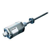
Magnetostriktives Positionsmesssystem — Bauform Stab
Marke:
Balluff
| Kategorie:
Messgeräte
| Dateigröße: 8.27 MB
Inhaltsverzeichnis
Deutsch
5
Inhaltsverzeichnis
5
Benutzerhinweise
7
Gültigkeit
7
Lieferumfang
7
Verwendete Symbole und Konventionen
7
Zulassungen und Kennzeichnungen
7
Sicherheit
8
Allgemeines zur Sicherheit
8
Bedeutung der Warnhinweise
8
Bestimmungsgemäße Verwendung
8
Entsorgung
8
Aufbau und Funktion
9
Vernünftigerweise Vorhersehbare Fehlanwendung
8
Aufbau
9
Funktion
9
Anzahl Positionsgeber
10
LED-Anzeige
10
Einbau und Anschluss
11
Einbau Vorbereiten
11
Einbauvarianten
11
BTL Einbauen
12
Einbauempfehlung für Hydraulikzylinder
12
Elektrischer Anschluss
13
Steckverbinder S32/Kabel
13
Steckverbinder S115
13
Schirmung und Kabelverlegung
14
Inbetriebnahme
15
Hinweise zum Betrieb
15
P-Schnittstelle
16
System in Betrieb Nehmen
15
DPI/IP-Verfahren
16
Funktion und Eigenschaften
16
Betrieb mit IP-Datenprotokoll
16
Protokollparameter
17
Technische Daten
18
Prinzip
16
Ausgang
18
Genauigkeit
18
Spannungsversorgung
18
Umgebungsbedingungen
18
Maße, Gewichte
19
Verbindung zur Auswerteeinheit
19
Zubehör
20
Befestigungsmutter
20
BTL-P-1028-15R (Sonderzubehör für Applikationen mit Stützrohranwendung)
20
Positionsgeber für BTL7
20
Steckverbinder S32
21
Frei Konfektionierbar
21
Konfektioniert
21
Steckverbinder S115, Konfektioniert
22
Typenschlüssel
23
Anhang
24
Typenschilder
24
Umrechnung Längeneinheiten
24
English
27
Approvals and Markings
29
Safety
30
Notes to the User
29
Scope of Delivery
29
Symbols and Conventions
29
Disposal
30
Construction and Function
31
Explanation of the Warnings
30
General Safety Notes
30
Intended Use
30
Reasonably Foreseeable Misuse
30
Construction
31
Function
31
LED Display
32
Installation and Connection
33
Number of Magnets
32
Installation Guidelines
33
Preparing for Installation
33
Installing the BTL
34
Installation Recommendation for Hydraulic Cylinders
34
Electrical Connection
35
Connector S32/Cable
35
Connector S115
35
Shielding and Cable Routing
36
Startup
37
Operating Notes
37
P Interface
38
Starting up the System
37
DPI/IP Method
38
Function and Characteristics
38
Protocol Parameters
39
Technical Data
40
Principle
38
Accuracy
40
Ambient Conditions
40
Output
40
Supply Voltage
40
Connection to the Evaluation Unit
41
Accessories
42
Dimensions, Weights
41
Btl-P-1028-15R
42
Magnets for BTL7
42
Mounting Nut
42
Connector Type S32
43
Freely Configurable
43
Preassembled
43
Connector Type S115, Preassembled
44
Type Code
45
Appendix
46
Converting Units of Length
46
Product Labels
46
Français
49
Fourniture
51
Homologations et Certifications
51
Sécurité
52
Informations Destinées à L'utilisateur
51
Symboles et Conventions Utilisés
51
Elimination
52
Structure et Fonction
53
Généralités Sur la Sécurité
52
Mauvais Usage Raisonnablement Prévisible
52
Signification des Avertissements
52
Utilisation Conforme aux Prescriptions
52
Fonction
53
Affichage à LED
54
Montage et Raccordement
55
Nombre de Capteurs de Position
54
Préparation du Montage
55
Variantes de Montage
55
Montage du BTL
56
Recommandation de Montage pour Vérin Hydraulique
56
Raccordement Électrique
57
Connecteur S32/Câble
57
Connecteur S115
57
Blindage et Pose des Câbles
58
Conseils D'utilisation
59
Interface P
60
Mise en Service du Système
59
ProcéDés DPI / IP
60
Fonction et Caractéristiques
60
Paramètre de Protocole
61
Caractéristiques Techniques
62
16 7.2 Conditions Ambiantes
62
Alimentation Électrique
62
Sorties
62
Connexion à L'unité D'analyse
63
Dimensions, Poids
63
Btl-P-1028-15R
64
Capteurs de Position pour BTL7
64
Ecrou de Fixation
64
Connecteur S32
65
À Assembler
65
Confectionné
65
Connecteur S115, Confectionné
66
Code de Type
67
Annexe
68
Conversion Unités de Longueur
68
Plaques Signalétiques
68
Italiano
71
Autorizzazioni E Contrassegni
73
Sicurezza
74
Avvertenze Per L'utente
73
Fornitura
73
Simboli E Segni Utilizzati
73
Informazioni DI Sicurezza Generali
74
Significato Delle Avvertenze
74
Smaltimento
74
Struttura E Funzione
75
Uso Conforme
74
Utilizzo Improprio Ragionevolmente Prevedibile
74
Funzionamento
75
Display LED
76
Montaggio E Collegamento
77
Numero Datori DI Posizione
76
Preparazione del Montaggio
77
Varianti DI Montaggio
77
Montaggio BTL
78
Suggerimento DI Montaggio Per Cilindro Idraulico
78
Collegamento Elettrico
79
Connettore S32/Cavo
79
Connettore S115
79
Schermatura E Posa Dei Cavi
80
Messa in Funzione
81
Avvertenze Per Il Funzionamento
81
Interfaccia P
82
Messa in Funzione del Sistema
81
Procedura DPI/IP
82
Funzione E Caratteristiche
82
Parametri del Protocollo
83
Dati Tecnici
84
Condizioni Ambientali
84
Tensione DI Alimentazione
84
Uscita
84
Collegamento con L'unità DI Valutazione
85
Dimensioni, Pesi
85
Btl-P-1028-15R
86
Dado DI Fissaggio
86
Datori DI Posizione Per BTL7
86
Connettore S32
87
Confezionabile Liberamente
87
Confezionato
87
Connettore S115, Confezionato
88
Legenda Codici DI Identificazione
89
Appendice
90
Conversione Delle Unità DI Lunghezza
90
Targhette DI Identificazione
90
Español
93
Homologaciones E Identificaciones
95
Seguridad
96
Indicaciones para el Usuario
95
Símbolos y Convenciones Utilizados
95
Volumen de Suministro
95
Aplicación Errónea Previsible desde un Punto de Vista Razonable
96
Eliminación de Desechos
96
Estructura y Funcionamiento
97
Generalidades sobre la Seguridad
96
Significado de las Advertencias
96
Uso Debido
96
Funcionamiento
97
Indicador LED
98
Montaje y Conexión
99
Número de Sensores de Posición
98
Preparación del Montaje
99
Variantes de Montaje
99
Montar el BTL
100
Recomendación de Montaje para Cilindros Hidráulicos
100
Conexión Eléctrica
101
Conector S32/Cable
101
Conector S115
101
Blindaje y Tendido de Cables
102
Puesta en Servicio
103
Indicaciones sobre el Servicio
103
Interfaz P
104
Puesta en Servicio del Sistema
103
Procedimiento DPI/IP
104
Funcionamiento y Características
104
Parámetros del Protocolo
105
Datos Técnicos
106
Alimentación de Tensión (Externa)
106
Condiciones Ambientales
106
Salida
106
Conexión a la Unidad de Evaluación
107
Medidas, Pesos
107
Btl-P-1028-15R
108
Sensores de Posición para BTL7
108
Tuerca de Fijación
108
Conector S32
109
Libremente Confeccionable
109
Confeccionado
109
Conector S115, Confeccionado
110
Código de Modelo
111
Anexo
112
Conversión de Unidades de Longitud
112
Placas de Características
112
Werbung
Balluff BTL7-P511-M serie Betriebsanleitung (115 Seiten)
Marke:
Balluff
| Kategorie:
Sensoren
| Dateigröße: 7.76 MB
Inhaltsverzeichnis
Deutsch
3
Inhaltsverzeichnis
3
Benutzerhinweise
5
Gültigkeit
5
Lieferumfang
5
Verwendete Symbole und Konventionen
5
Zulassungen und Kennzeichnungen
5
Sicherheit
6
Allgemeines zur Sicherheit des Wegmesssystems
6
Bedeutung der Warnhinweise
6
Bestimmungsgemäße Verwendung
6
Entsorgung
6
Aufbau und Funktion
7
Aufbau
7
Funktion
7
Anzahl Positionsgeber
8
LED-Anzeige
8
Einbau und Anschluss
9
Einbau Vorbereiten
9
Einbauvarianten
9
Wegaufnehmer Einbauen
10
Einbauempfehlung für Hydraulikzylinder
10
Elektrischer Anschluss
11
Steckverbinder S32/Kabel
11
Steckverbinder S115
11
Steckverbinder S135
11
Schirmung und Kabelverlegung
12
Inbetriebnahme
13
Hinweise zum Betrieb
13
P-Schnittstelle
14
System in Betrieb Nehmen
13
DPI/IP-Verfahren
14
Funktion und Eigenschaften
14
Protokollparameter
15
Technische Daten
16
Prinzip
14
Ausgang
16
Genauigkeit
16
Spannungsversorgung (Extern)
16
Umgebungsbedingungen
16
Maße, Gewichte
17
Verbindung zur Auswerteeinheit
17
Zubehör
19
Steckverbinder und Kabel
19
BKS-S32/S33M-00, Frei Konfektionierbar
19
Bks-S232/S233-Pu
19
Bks-S115/S116-Pu
20
BKS-S135/S136M-00, Frei Konfektionierbar
20
Typenschlüssel
21
Anhang
22
Typenschild
22
Umrechnung Längeneinheiten
22
English
26
Approvals and Markings
28
Safety
29
Notes to the User
28
Scope of Delivery
28
Symbols and Conventions
28
Disposal
29
Construction and Function
30
Explanation of the Warnings
29
General Safety Notes for the Position Measuring System
29
Intended Use
29
Construction
30
Function
30
LED Display
31
Installation and Connection
32
Number of Magnets
31
Installation Guidelines
32
Preparing for Installation
32
Installing the Transducer
33
Installation Recommendation for Hydraulic Cylinders
33
Electrical Connection
34
Connector S32/Cable
34
Connector S115
34
Connector S135
34
Shielding and Cable Routing
35
Startup
36
Operating Notes
36
P Interface
37
Starting up the System
36
DPI/IP Method
37
Function and Characteristics
37
Protocol Parameters
38
Technical Data
39
Principle
37
Accuracy
39
Ambient Conditions
39
Output
39
Supply Voltage (External)
39
Dimensions, Weights
40
Update Rate and Clock Frequency
40
Accessories
41
Mounting Nut
41
Connectors and Cables
42
BKS-S32/S33M-00, Freely Configurable
42
Bks-S232/S233-Pu
42
Bks-S115/S116-Pu
43
BKS-S135/S136M-00, Freely Configurable
43
Type Code Breakdown
44
Appendix
45
Converting Units of Length
45
Part Labels
45
Español
49
Homologaciones E Identificaciones
51
Seguridad
52
Indicaciones para el Usuario
51
Símbolos y Convenciones Utilizados
51
Volumen de Suministro
51
Eliminación de Desechos
52
Estructura y Funcionamiento
53
Generalidades sobre la Seguridad del Sistema de Medición de Desplazamiento
52
Significado de las Advertencias
52
Uso Debido
52
Funcionamiento
53
Indicador LED
54
Montaje y Conexión
55
Número de Sensores de Posición
54
Preparación del Montaje
55
Variantes de Montaje
55
Montaje del Transductor de Desplazamiento
56
Recomendación de Montaje para Cilindros Hidráulicos
56
Conexión Eléctrica
57
Conector S32/Cable
57
Conector S115
57
Conector S135
57
Blindaje y Tendido de Cables
58
Puesta en Marcha
59
Indicaciones sobre el Servicio
59
Interfaz P
60
Puesta en Servicio del Sistema
59
Procedimiento DPI/IP
60
Funcionamiento y Características
60
Parámetros del Protocolo
61
Datos Técnicos
62
16 7.2 Condiciones Ambientales
62
Alimentación de Tensión (Externa)
62
Salida
62
Conexión a la Unidad de Evaluación
63
Accesorios
64
Medidas, Pesos
63
Sensores de Posición
64
Tuerca de Fijación
64
Conectores y Cables
65
BKS-S32/S33M-00, Libremente Confeccionable
65
Bks-S232/S233-Pu
65
Bks-S115/S116-Pu
66
BKS-S135/S136M-00, Libremente Confeccionable
66
Código de Modelo
67
Anexo
68
Conversión de Unidades de Longitud
68
Placas de Características
68
Français
72
Conditionnement
74
Guide D'utilisation
74
Homologations et Certifications
74
Sécurité
75
Symboles et Conventions Utilisés
74
Elimination
75
Structure et Fonction
76
Généralités Sur la Sécurité du Système de Mesure de Déplacement
75
Signification des Avertissements
75
Utilisation Conforme aux Prescriptions
75
Fonction
76
Affichage à LED
77
Montage et Raccordement
78
Nombre de Capteurs de Position
77
Préparation du Montage
78
Variantes de Montage
78
Montage du Capteur de Déplacement
79
Recommandation de Montage pour Vérin Hydraulique
79
Raccordement Électrique
80
Connecteur S32/Câble
80
Connecteur S115
80
Connecteur S135
80
Blindage et Pose des Câbles
81
Conseils D'utilisation
82
Mise en Service du Système
82
ProcéDés DPI / IP
83
Fonction et Caractéristiques
83
Paramètre de Protocole
84
Caractéristiques Techniques
85
Alimentation Électrique (Externe)
85
Conditions Ambiantes
85
Sorties
85
Connexion à L'unité D'analyse
86
Accessoires
87
Dimensions, Poids
86
Capteurs de Position
87
Ecrou de Fixation
87
Connecteurs et Câbles
88
BKS-S32/S33M-00, à Assembler
88
Bks-S232/S233-Pu
88
Bks-S115/S116-Pu
89
BKS-S135/S136M-00, à Assembler
89
Code de Type
90
Annexe
91
Conversion Unités de Longueur
91
Plaques Signalétiques
91
Italiano
95
Autorizzazioni E Contrassegni
97
Sicurezza
98
Avvertenze Per L'utente
97
Fornitura
97
Simboli E Segni Utilizzati
97
Informazioni DI Sicurezza Sul Sistema DI Misura Della Corsa
98
Significato Delle Avvertenze
98
Smaltimento
98
Struttura E Funzione
99
Uso Conforme
98
Funzione
99
Display LED
100
Montaggio E Collegamento
101
Numero Datori DI Posizione
100
Preparazione del Montaggio
101
Varianti DI Montaggio
101
Montaggio del Trasduttore DI Posizione
102
Suggerimento DI Montaggio Per Cilindro Idraulico
102
Collegamento Elettrico
103
Connettore S32/Cavo
103
Connettore S115
103
Schermatura E Posa Dei Cavi
104
Avvertenze Per Il Funzionamento
105
Interfaccia P
106
Messa in Funzione del Sistema
105
Procedura DPI/IP
106
Funzione E Caratteristiche
106
Parametri del Protocollo
107
Dati Tecnici
108
Condizioni Ambientali
108
Tensione DI Alimentazione (Esterna)
108
Uscita
108
Collegamento con L'unità DI Valutazione
109
Accessori
110
Dimensioni, Pesi
109
Dado DI Fissaggio
110
Datori DI Posizione
110
Connettori E Cavi
111
BKS-S32/S33M-00, Confezionabile Liberamente
111
Bks-S232/S233-Pu
111
Bks-S115/S116-Pu
112
BKS-S135/S136M-00, Confezionabile Liberamente
112
Codice Identificativo
113
Appendice
114
Conversione Delle Unità DI Lunghezza
114
Targhette DI Identificazione
114
Balluff BTL7-P511-M serie Betriebsanleitung (112 Seiten)
Magnetostriktives Positionsmesssystem
Marke:
Balluff
| Kategorie:
Industrielle Ausrüstung
| Dateigröße: 4 MB
Inhaltsverzeichnis
Deutsch
5
Inhaltsverzeichnis
5
Benutzerhinweise
7
Gültigkeit
7
Lieferumfang
7
Verwendete Symbole und Konventionen
7
Zulassungen und Kennzeichnungen
7
Sicherheit
8
Allgemeines zur Sicherheit
8
Bedeutung der Warnhinweise
8
Bestimmungsgemäße Verwendung
8
Entsorgung
8
Aufbau und Funktion
9
Vernünftigerweise Vorhersehbare Fehlanwendung
8
Aufbau
9
Anzahl Positionsgeber
10
Funktion
10
LED-Anzeige
10
Einbau und Anschluss
11
Einbau Vorbereiten
11
Einbauvarianten
11
BTL Einbauen
12
Einbauempfehlung für Hydraulikzylinder
12
Elektrischer Anschluss
13
Steckverbinder S32 und Kabelanschluss
13
Schirmung und Kabelverlegung
13
Inbetriebnahme
14
Hinweise zum Betrieb
14
P-Schnittstelle
15
System in Betrieb Nehmen
14
DPI/IP-Verfahren
15
Funktion und Eigenschaften
15
Betrieb mit IP-Datenprotokoll
15
Protokollparameter
16
Technische Daten
17
Prinzip
15
Ausgang
17
Genauigkeit
17
Spannungsversorgung (Extern)
17
Umgebungsbedingungen
17
Maße, Gewichte
18
Verbindung zur Auswerteeinheit
19
Zubehör
20
Befestigungsmutter
20
Btl-P-1028-15R
20
Gleitbuchse
20
Positionsgeber für TB/TZ
20
Steckverbinder S32
21
Frei Konfektionierbar
21
Konfektioniert
21
Typenschlüssel
22
Anhang
23
Typenschild
23
Umrechnung Längeneinheiten
23
English
27
Approvals and Markings
29
Safety
30
Notes to the User
29
Scope of Delivery
29
Symbols and Conventions
29
Disposal
30
Construction and Function
31
Explanation of the Warnings
30
General Safety Notes
30
Intended Use
30
Reasonably Foreseeable Misuse
30
Construction
31
Function
32
LED Display
32
Installation and Connection
33
Number of Magnets
32
Installation Guidelines
33
Preparing for Installation
33
Installing the BTL
34
Installation Recommendation for Hydraulic Cylinders
34
Electrical Connection
35
S32 Connector and Cable Connection
35
Shielding and Cable Routing
35
Startup
36
Operating Notes
36
P Interface
37
Starting up the System
36
DPI/IP Method
37
Function and Characteristics
37
Protocol Parameters
38
Technical Data
39
Principle
37
Accuracy
39
Ambient Conditions
39
Output
39
Supply Voltage (External)
39
Dimensions, Weights
40
Connection to the Evaluation Unit
41
Accessories
42
Bearing Bush
42
Btl-P-1028-15R
42
Magnet for TB/TZ
42
Mounting Nut
42
Connector Type S32
43
Freely Configurable
43
Preassembled
43
Type Code
44
Appendix
45
Converting Units of Length
45
Part Label
45
Français
49
Fourniture
51
Guide D'utilisation
51
Homologations et Certifications
51
Sécurité
52
Symboles et Conventions Utilisés
51
Elimination
52
Structure et Fonctionnement
53
Généralités Sur la Sécurité
52
Mauvais Usage Raisonnablement Prévisible
52
Signification des Avertissements
52
Utilisation Conforme aux Prescriptions
52
Affichage à LED
54
Montage et Raccordement
55
Fonction
54
Nombre de Capteurs de Position
54
Préparation du Montage
55
Variantes de Montage
55
Montage du BTL
56
Recommandation de Montage pour Vérin Hydraulique
56
Blindage et Pose des Câbles
57
Raccordement Électrique
57
Connecteur S32 et Raccordement Par Câble
57
Conseils D'utilisation
58
Interface P
59
Mise en Service du Système
58
ProcéDé DPI/IP
59
Fonctionnement et Propriétés
59
Paramètres de Protocole
60
Caractéristiques Techniques
61
Alimentation Électrique (Externe)
61
Conditions Ambiantes
61
Sortie
61
Dimensions, Poids
62
Connexion à L'unité D'exploitation
63
Accessoires
64
Btl-P-1028-15R
64
Capteurs de Position pour TB/TZ
64
Douille de Guidage
64
Ecrous de Fixation
64
Connecteur S32
65
À Assembler
65
Confectionné
65
Code de Type
66
Annexe
67
Conversion des Unités de Longueur
67
Plaque Signalétique
67
Italiano
71
Autorizzazioni E Contrassegni
73
Sicurezza
74
Avvertenze Per L'utente
73
Fornitura
73
Simboli E Segni Utilizzati
73
Informazioni DI Sicurezza
74
Significato Delle Avvertenze
74
Smaltimento
74
Struttura E Funzionamento
75
Uso Conforme
74
Utilizzo Improprio Ragionevolmente Prevedibile
74
Funzionamento
76
Indicatore LED
76
Montaggio E Collegamento
77
Numero Datori DI Posizione
76
Preparazione del Montaggio
77
Varianti DI Montaggio
77
Montaggio BTL
78
Suggerimento DI Montaggio Per Cilindro Idraulico
78
Collegamento Elettrico
79
Connettore S32 E Collegamento Cavo
79
Schermatura E Posa Dei Cavi
79
Messa in Funzione
80
Avvertenze Per Il Funzionamento
80
Interfaccia P
81
Messa in Funzione del Sistema
80
Procedura DPI/IP
81
Funzioni E Caratteristiche
81
Parametri del Protocollo
82
Dati Tecnici
83
Condizioni Ambientali
83
Tensione DI Alimentazione (Esterna)
83
Uscita
83
Dimensioni E Pesi
84
Collegamento con Il Processore
85
Accessori
86
Boccola DI Scorrimento
86
Btl-P-1028-15R
86
Dado DI Fissaggio
86
Datore DI Posizione Per TB/TZ
86
Connettore S32
87
Confezionabile Liberamente
87
Confezionato
87
Legenda Codici DI Identificazione
88
Appendice
89
Conversione Delle Unità DI Lunghezza
89
Targhetta Identificativa
89
Español
93
Homologaciones E Identificaciones
95
Seguridad
96
Indicaciones para el Usuario
95
Símbolos y Convenciones Utilizados
95
Volumen de Suministro
95
Aplicación Errónea Previsible desde un Punto de Vista Razonable
96
Eliminación de Desechos
96
Estructura y Funcionamiento
97
Generalidades sobre la Seguridad
96
Significado de las Advertencias
96
Uso Debido
96
Funcionamiento
98
Indicador LED
98
Montaje y Conexión
99
Número de Sensores de Posición
98
Preparación del Montaje
99
Variantes de Montaje
99
Montar el BTL
100
Recomendación de Montaje para Cilindros Hidráulicos
100
Blindaje y Tendido de Cables
101
Puesta en Servicio
102
Conexión Eléctrica
101
Conector S32 y Conexión de Cable
101
Indicaciones sobre el Servicio
102
Interfaz P
103
Puesta en Servicio del Sistema
102
Procedimiento DPI/IP
103
Funcionamiento y Características
103
Parámetros del Protocolo
104
Datos Técnicos
105
Alimentación de Tensión (Externa)
105
Condiciones Ambientales
105
Salida
105
Medidas, Pesos
106
Conexión al Procesador
107
Accesorios
108
Btl-P-1028-15R
108
Manguito Deslizante
108
Sensor de Posición para TB/TZ
108
Tuerca de Fijación
108
Conector S32
109
Libremente Confeccionable
109
Confeccionado
109
Código de Modelo
110
Anexo
111
Conversión de Unidades de Longitud
111
Placa de Características
111
Werbung
Balluff BTL7-P511-M serie Betriebsanleitung (120 Seiten)
Marke:
Balluff
| Kategorie:
Sensoren
| Dateigröße: 5.24 MB
Balluff BTL7-P511-M serie Kurzanleitung (17 Seiten)
Marke:
Balluff
| Kategorie:
Sensoren
| Dateigröße: 1.15 MB
Inhaltsverzeichnis
Bestimmungsgemäße Verwendung
2
Elektrischer Anschluss
3
Einbau
3
Downloading Further Instructions
4
Electrical Connection
5
Raccordement Électrique
7
Collegamento Elettrico
9
Conexión Eléctrica
11
Balluff BTL7-P511-M serie Kurzanleitung (14 Seiten)
Magnetostriktives Positionsmesssystem – Bauform Stab
Marke:
Balluff
| Kategorie:
Messgeräte
| Dateigröße: 1.62 MB
Werbung
Verwandte Produkte
Balluff BTL7-...-ZA10 Serie
Balluff BTL7-A serie
Balluff BTL7-C serie
Balluff BTL7-G serie
Balluff BTL7-E serie
Balluff BTL7-Axx-Mxxxx-K-NEX-SR32/K Serie
Balluff BTL7-Cxx-Mxxxx-K-NEX-SR32/K Serie
Balluff BTL7-G5xx-Mxxxx-K-NEX-SR32/K Serie
Balluff BTL7-Axx-Mxxxx-K8-NEX-SR32/K Serie
Balluff BTL7-Cxx-Mxxxx-K8-NEX-SR32/K Serie
Balluff Kategorien
Sensoren
Messgeräte
Module
Netzwerkhardware
Industrielle Ausrüstung
Weitere Balluff Anleitungen
Anmelden
Anmelden
ODER
Mit Facebook anmelden
Mit Google anmelden
Anleitung hochladen
Von PC hochladen
Von URL hochladen