Herunterladen Diese Seite drucken

Werbung

Verfügbare Sprachen
  • DE

Verfügbare Sprachen

  • DEUTSCH, seite 23
FR
2 / 3-12 / 73-80
EN
2 / 13-22 / 73-80
DE
2 / 23-32 / 73-80
ES
2 / 33-42 / 73-80
RU
2 / 43-52 / 73-80
NL
2 / 53-62 / 73-80
IT
2 / 63-72 / 73-80
73502_V4_23/06/2021
IMS CUTTER 45 CT
ims-welding.com

Werbung

loading

Inhaltszusammenfassung für ims PRO IMS CUTTER 45 CT

  • Seite 1 IMS CUTTER 45 CT 2 / 3-12 / 73-80 2 / 13-22 / 73-80 2 / 23-32 / 73-80 2 / 33-42 / 73-80 2 / 43-52 / 73-80 2 / 53-62 / 73-80 2 / 63-72 / 73-80 ims-welding.com...
  • Seite 2 IMS CUTTER 45 CT FIG-1 Matière : Épaisseur : mm FIG-2...
  • Seite 3 IMS CUTTER 45 CT INSTRUCTIONS DE SÉCURITÉ CONSIGNE GÉNÉRALE Ces instructions doivent être lues et bien comprises avant toute opération. Toute modification ou maintenance non indiquée dans le manuel ne doit pas être entreprise. Tout dommage corporel ou matériel dû à une utilisation non-conforme aux instructions de ce manuel ne pourra être retenu à la charge du fabricant.
  • Seite 4 IMS CUTTER 45 CT RISQUE DE FEU ET D’EXPLOSION Protéger entièrement la zone de coupage, les matières inflammables doivent être éloignées d’au moins 11 mètres. Un équipement anti-feu doit être présent à proximité des opérations de coupage. Attention aux projections de matières chaudes ou d’étincelles et même à travers des fissures, elles peuvent être source d’incendie ou d’explosion.
  • Seite 5 IMS CUTTER 45 CT RECOMMANDATIONS POUR ÉVALUER LA ZONE ET L’INSTALLATION DE COUPAGE Généralités L’utilisateur est responsable de l’installation et de l’utilisation du matériel de coupage à l’arc suivant les instructions du fabricant. Si des perturbations électromagnétiques sont détectées, il doit être de la responsabilité de l’utilisateur du matériel de coupage à l’arc de résoudre la situation avec l’assistance technique du fabricant.
  • Seite 6 IMS CUTTER 45 CT • Le matériel est de degré de protection IP23, signifiant : - Une protection contre l’accès aux parties dangereuses des corps solides de diam ≥12.5mm et, - Une protection contre la pluie dirigée à 60° par rapport à la verticale.
  • Seite 7 IMS CUTTER 45 CT INTERFACE HOMME-MACHINE (IHM) (FIG-2) Indicateur de protection thermique Indicateur de coupe tôle ajourée avec redémarrage de l’arc-pilote Indicateur «arrêt lié à une intervention sur la torche» Potentiomètre de réglage de l’intensité Indicateur de perturbation du fonctionnement normal Bar-graph indicateur de pression Indicateur de coupe tôle pleine...
  • Seite 8 IMS CUTTER 45 CT CONFIGURATION DE LA TORCHE (MT-70) Référez-vous aux abaques sur le côté du poste pour sélectionner le consommable adapté. Mise en place de la torche : - Brancher la torche sur le connecteur prévu à cet effet.
  • Seite 9 IMS CUTTER 45 CT RÉGLAGE DE LA PRESSION D’AIR Afin d’obtenir des performances et des durées de vie des consommables optimales, il est très important de régler correctement la pression d’air. Il est recommandé de vérifier/régler la pression en cas : - de changement de point de raccordement ou d’installation pneumatique...
  • Seite 10 IMS CUTTER 45 CT COUPE MANUELLE À PARTIR DU BORD DE LA PIÈCE : La pince de masse fixée à la pièce, maintenez le patin de la torche perpendiculaire (90°) à l’extrémité de la pièce. Appuyez sur la gâchette de la torche pour amorcer l’arc jusqu’à ce que celui-ci ait complètement entamé...
  • Seite 11 IMS CUTTER 45 CT SÉCURITÉS Interventions sur la torche L’opérateur sera amené à intervenir sur la torche et ses accessoires (changement des consommables, débranchement de la torche). Si le découpeur Plasma est allumé dans ce cas de figure l’indicateur «arrêt lié à une intervention sur la torche» (FIG 2 - 2) s’allumera pour signaler que le générateur a bien détecté...
  • Seite 12 IMS CUTTER 45 CT Vérifier la bonne rétractation de l’électrode. Vérifier l’installation pneumatique L’électrode ne s’est pas rétractée ou l’air Pas d’arc (diamètre des tuyaux trop petit et/ou en sortie n’est pas suffisant. tuyaux trop longs, tuyau pincé). Vérifier le dimensionnement du compresseur.
  • Seite 13 IMS CUTTER 45 CT SAFETY INSTRUCTIONS GENERAL INSTRUCTIONS Read and understand the following safety instructions before use. Any modification or updates that are not specified in the instruction’s manual should not be underta- ken. The manufacturer is not liable for any injury or damage due to a non-compliance with the instructions featured in this manual.
  • Seite 14 IMS CUTTER 45 CT FIRE AND EXPLOSION RISKS Protect the entire working area and ensure that flammable items are stored at a distance of at least 11 meters. Fire extinguishing equipment must be kept in close proximity when cutting materials.
  • Seite 15 IMS CUTTER 45 CT RECOMMENDATIONS FOR WELDING AREA ASSESSMENT AND WELDING Overview The user is responsible for the installation and use of the arc cutting equipment according to the manufacturer’s instructions. If electromagnetic disturbances are detected, the user is responsible for resolving the situation with the manufacturer’s technical assistance. In certain cases, this corrective action may be as simple as earthing the cutting circuit.
  • Seite 16 IMS CUTTER 45 CT The manufacturer does not accept any liability in relation to damages caused to objects or harm caused to persons as the result of incorrect and/or dangerous use of the machine. MAINTENANCE / RECOMMENDATIONS Ensure the machine is unplugged from the mains, and then wait 2 minutes before carrying out maintenance work. Inside, voltages and currents are high and dangerous.
  • Seite 17 IMS CUTTER 45 CT INTERFACE (MMI) (FIG-2) Thermal protection indicator Full sheet cutting indicator with the pilot-arc restart Indicator «Stop caused by intervention on the torch» Current setting potentiometer. Malfunction (machine is not functioning normally) indicator Bar-graph Pressure indicator Full sheet cutting indicator Indicator «insufficient pressure»...
  • Seite 18 IMS CUTTER 45 CT TORCH SETUP (MT-70) Refer to the charts on the side of the machine to choose the appropriate consumable. Torch set-up - Plug the torch into the appropriate connector - No machine settings adjustment required Manual cutting...
  • Seite 19 IMS CUTTER 45 CT AIR PRESSURE ADJUSTMENT In order to improve cutting performance, make sure air pressure is set to an appropriate level. It is recommended to check / adjust the pressure in case: - of change of connection point or of pneumatic installation...
  • Seite 20 IMS CUTTER 45 CT MANUAL CUT FROM THE EDGE OF THE WORKPIECE: The earth clamp attached to the metal piece, hold the torch pad in perpendicular position (90°) to the end of the workpiece. Pull the trigger of the torch to prime the arc until the torch has completely pass through the part.
  • Seite 21 IMS CUTTER 45 CT PROTECTIONS Intervention on the torch The operator will have to manipulate and open the torch and its accessories (change of consumables, disconnection of the torch). If the Plasma cutter is switched on during intervention, the screen will display «stop caused by intervention on the torch» (FIG 2 - 2) meaning that the machine has detected an intervention and that it can be carried out safely.
  • Seite 22 IMS CUTTER 45 CT Check that the electrode is properly retracted. Check the pneumatic system (check The electrode has not retracted or there No arc if the hose diameter too small or is not enough air coming out. hose too long, if the hose pinched or kinked).
  • Seite 23 IMS CUTTER 45 CT SICHERHEITSANWEISUNGEN ALLGEMEIN Die Nichtbeachtung dieser Anweisungen und Hinweise kann zu schweren Personen- und Sachschä- den führen. Nehmen Sie keine Wartungarbeiten oder Veränderungen am Gerät vor, die nicht in der Anleitung gennant werden. Der Hersteller haftet nicht für Verletzungen oder Schäden, die durch unsachgemäße Handhabung dieses Gerätes enstanden sind.
  • Seite 24 IMS CUTTER 45 CT Achtung! Bei Schneidarbeiten in kleinen Räumen müssen Sicherheitsabstände besonders beachtet werden. Beim Schneiden von Blei, auch in Form von Überzügen, verzinkten Teilen, Kadmium, «kadmierte Schrauben», Beryllium (meist als Legierungsbestandteil, z.B. Beryllium-Kupfer) und andere Metalle entstehen giftige Dämpfe. Erhöhte Vorsicht gilt beim Schneiden von Behältern. Entleeren und reinigen Sie diese zuvor. Um die Bildung von Giftgasen zu vermeiden bzw.
  • Seite 25 IMS CUTTER 45 CT HINWEIS ZUR PRÜFUNG DES SCHWEISSPLATZES UND DER SCHWEISSANLAGE Allgemein Der Anwender ist für den korrekten Einsatz des Schneidgerätes und des Materials gemäß den Herstellerangaben verantwortlich. Treten elektromagnetischer Störungen auf, liegt es in der Verantwortung des Anwenders mit Hilfe des Herstellers eine Lösung zu finden. Die korrekte Erdung des Schneidplatzes inklusive aller Geräte hilft in vielen Fällen.
  • Seite 26 
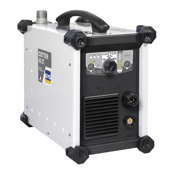
IMS CUTTER 45 CT WARTUNG / HINWEISE Trennen SIe das Gerät von der Stromversorgung und warten Sie bis der Lüfter nicht mehr läuft. Erst dann dürfen Sie das Gerät warten. Die Spannungen und Ströme im Gerät sind hoch und gefährlich.
  • Seite 27 IMS CUTTER 45 CT BEDIENFELD (ABB. 2) Anzeige zum Thermoschutz Anzeige "Lochblechmodus" Anzeige "Ausschaltung wegen Manipuliation am Brenner" Drehregler für Spannungseinstellung Anzeige einer Störung Bar-Graph, Druckanzeige Anzeige "Vollblechmodus" Anzeige "unzureicheder Druck" Modusauswahltaste Taste zum Testen und Einstellen des Luftdrucks Anzeige "Vollblechmodus mit Verriegelung der Brennertaste für Anzeige "laufende Luftdrucktest"...
  • Seite 28 IMS CUTTER 45 CT KONFIGUARATION DES BRENNERS (MT-70) Die passenden Verschleißteile sind auf der Tabelle auf der Seite des Geräts abgebildet. Brennermontage: - Stecken Sie den Brenner in die Anschlussbuchse. - Keine Änderung der Einstellung erforderlich. Manueller Schnitt 20-50 A...
  • Seite 29 IMS CUTTER 45 CT EINSTELLUNG DES LUFTDRUCKS Für optimale Leistung und hohe Lebensdauer der Verschleißteile muss der Luftdruck richtig eingestellt werden. Der Luftdruck sollte überprüft/eingestellt werden, bei: - Austausch der Druckluftkupplung oder des Anschlusses - Austausch des Brenners - Austausch der Verschleißteile...
  • Seite 30 IMS CUTTER 45 CT MANUELLER SCHNITT AN DER KANTE DES WERKSTÜCKS: Halten Sie die Brennerdüse senkrecht (90°) zur Kante des Werkstücks mit ange- brachter Masseklemme Betätigen Sie die Brennertaste, um den Lichtbogen zu zünden. Halten Sie den Brenner, bis der Lichtbogen das Werkstück durchschnitten hat.
  • Seite 31 IMS CUTTER 45 CT SICHERHEITEN Überprüfung des Brenners Der Brenner und die Verschleißteile müssen regelmäßig überprüft werden (Wechsel der Verschleißteile, Abschalten des Brenners). Wenn das Gerät bei der Überprüfung eingeschaltet ist, erscheint die Anzeige «Ausschalten wegen Manipulation am Brenner» (ABB 2 - 2), um anzuzeigen, dass das Gerät die Brennermanipulation erkennt hat und das die Überprüfung ohne Gefahr erfolgen kann.
  • Seite 32 IMS CUTTER 45 CT Prüfen Sie, ob die Elektrode richtig eingefahren ist. Überprüfen Sie die pneumatische Die Elektrode hat sich nicht zurückge- Installation (Schlauchdurchmesser kein Lichtbogen zogen oder es kommt nicht genügend zu klein und/oder Schlauch zu lang, Luft heraus gequetschter Schlauch) Überprüfung der...
  • Seite 33 IMS CUTTER 45 CT INSTRUCCIONES DE SEGURIDAD CONSIGNA GENERAL Estas instrucciones se deben leer y comprender antes de toda operación. Toda modificación o mantenimiento no indicado en el manual no se debe llevar a cabo. Todo daño físico o material debido a un uso no conforme con las instrucciones de este manual no podrá atribuírsele al fabricante.
  • Seite 34 IMS CUTTER 45 CT RIESGO DE FUEGO Y DE EXPLOSIÓN Proteja completamente la zona de corte, los materiales inflamables deben alejarse al menos 11 metros. Cerca de la zona de operaciones de corte debe haber un anti-incendios. Atención a las proyecciones de materiales calientes o chispas incluso a través de las fisuras. Pueden generar un incendio o una explosión.
  • Seite 35 IMS CUTTER 45 CT RECOMENDACIONES PARA EVALUAR LA ZONA Y LA INSTALACIÓN DE SOLDADURA Generalidades El usuario se responsabiliza de instalar y usar el material de corte al arco siguiendo las instrucciones del fabricante. Si se detectan alteraciones electromagnéticas, el usuario debe resolver la situación siguiendo las recomendaciones del manual de usuario o consultando el servicio técnico del fabricante.
  • Seite 36 IMS CUTTER 45 CT El fabricante no asume ninguna responsabilidad respecto a daños provocados a personas y objetos debido a un uso incorrecto y peligroso de este aparato. MANTENIMIENTO / CONSEJOS Interrumpa el suministro eléctrico, luego desconecte el enchufe y espere 2 minutos antes de trabajar sobre el aparato. En su interior, la tensión y la intensidad son elevadas y peligrosas.
  • Seite 37 IMS CUTTER 45 CT INTERFAZ HOMBRE-MÁQUINA (IHM) (FIG-2) Indicador de protección térmica Indicador de corte de chapa perforada con reinicio de arco-piloto Indicador "Parada ligada a una intervención sobre la antorcha" Potenciómetro de ajuste de intensidad Indicador de perturbación del funcionamiento normal Barra gráfica de indicador de presión...
  • Seite 38 IMS CUTTER 45 CT CONFIGURACIÓN DE LA ANTORCHA (MT-70) Refiérase a los abacos en la parte lateral del equipo para seleccionar el consumible adaptado. Corte manual 20-50 A 037564 037571 037557 (x 5) 037601 037625 (x 5) Para el corte : Hay uno calibre de consumibles disponible : Corte automático...
  • Seite 39 IMS CUTTER 45 CT AJUSTE DE LA PRESIÓN DE AIRE Para obtener los rendimientos y duraciones de vida de los consumibles óptimos, es importante ajustar correctamente la presión de aire. Se recomienda comprobar / ajustar la presión de aire en caso : - cambio de punto de conexión o instalación neumática.
  • Seite 40 IMS CUTTER 45 CT CORTE MANUAL A PARTIR DEL BORDE DE LA PIEZA: Con la pinza de masa fijada a la pieza, mantenga el soporte de la antorcha de forma perpendicular (90º) a la extremidad de la pieza. Presione sobre el gatillo de la antorcha para cebar el arco hasta que se inicie.
  • Seite 41 IMS CUTTER 45 CT SEGURIDAD Intervención sobre la antorcha El operador deberá intervenir en algún momento sobre la antorcha y sus accesorios (cambio de consumibles, desconexión de la antorcha). Si el cortador Plasma está encendido, en este caso el indicador «Parada ligada a una intervención sobre la antorcha» (FIG 2 - 2) se encenderá...
  • Seite 42 IMS CUTTER 45 CT Compruebe que el electrodo está bien retraído Compruebe la instalación neumática El electrodo no se ha retraído o no sale Sin arco (diámetro de la manguera demasiado aire suficiente pequeño y/o manguera demasiado larga, manguera pellizcada) Comprobar el tamaño del compresor...
  • Seite 43 IMS CUTTER 45 CT ПРАВИЛА БЕЗОПАСНОСТИ ОБЩИЕ УКАЗАНИЯ Эти указания должны быть прочтены и поняты до начала сварочных работ. Изменения и ремонт, не указанные в этой инструкции, не должны быть предприняты. Производитель не несет ответственности за травмы и материальные повреждения связанные с несоответствующим данной инструкции...
  • Seite 44 IMS CUTTER 45 CT Будьте внимательны: резка в небольших помещениях требует наблюдения на безопасном расстоянии. Кроме того, резка некоторых металлов, содержащих свинец, кадмий, цинк, ртуть или даже бериллий, может быть чрезвычайно вредной. Следует очистить от жира детали перед резкой. Газовые баллоны должны храниться в открытых или хорошо проветриваемых помещениях. Они должны быть в вертикальном положении и...
  • Seite 45 IMS CUTTER 45 CT РЕКОМЕНДАЦИИ ДЛЯ ОЦЕНКИ СРЕДЫ И УСТАНОВКИ СВАРОЧНОГО ОБОРУДОВАНИЯ Общие положения Пользователь отвечает за установку и использование установки ручной дуговой резки, следуя указаниям производителя. При обнаружении электромагнитных излучений пользователь аппарата ручной дуговой резки должен разрешить проблему с помощью технической поддержки...
  • Seite 46 IMS CUTTER 45 CT • Оборудование имеет защиту IP23, что означает : - Защиту от попадания в опасные зоны твердых тел диаметром ≥12,5мм и, - Защиту против капель дождя, направленных под углом 60° относительно вертикали. Это оборудование может быть использовано вне помещения соответственно классу защиты IP23.
  • Seite 47 IMS CUTTER 45 CT ИНТЕРФЕЙС ЧЕЛОВЕК-МАШИНА (IHM) (FIG-2) Индикатор резки решётчатой заготовки с возобновлением Индикатор термозащиты дежурной дуги Индикатор «остановки в связи с действиями с горелкой» Потенциометр настройки сварочного тока Индикатор нарушения нормального функционирования Шкальный индикатор давления Индикатор резки сплошной заготовки...
  • Seite 48 IMS CUTTER 45 CT НАСТРОЙКА ГОРЕЛКИ (MT-70) См. таблицу сбоку аппарата для выбора нужных комплектующих. Подключение горелки: - Подсоедините горелку к соответствующему коннектору. - Для этого нет необходимости вносить какие-либо изменения в настройки аппарата. Ручная резка 20-50 A 037564 037571...
  • Seite 49 IMS CUTTER 45 CT РЕГУЛИРОВКА ДАВЛЕНИЯ ВОЗДУХА Для оптимизации рабочих характеристик резки и сроков службы расходных комплектующих необходимо правильно отрегулировать давление воздуха. Рекомендуется проверять/регулировать давление в случаях: - смены точки подключения или пневматической установки - использования горелки с другой длиной рукава...
  • Seite 50 IMS CUTTER 45 CT РУЧНАЯ РЕЗКА ОТ КРАЯ ДЕТАЛИ: После закрепления массы на деталь держите подошву горелки перпендикулярно (90°) к краю детали. Нажмите на триггер горелки для поджига дуги до тех пор, пока эта дуга не начнет прорезать деталь. Как только деталь прорезана, слегка протащите подошву по детали для...
  • Seite 51 IMS CUTTER 45 CT ЗАЩИТЫ Действия с горелкой Оператору нужно будет в какой-то момент поменять комплектующие горелки, отключить ее и т.д. Если при этом аппарат плазменной резки включен, то загорится индикатор «остановки, связанной с действием с горелкой» (FIG 2 - 2), чтобы предупредить, что источник обнаружил действие с горелкой и что оно может быть совершено в полной...
  • Seite 52 IMS CUTTER 45 CT Проверьте правильно ли втянут электрод Проверьте пневматическую установку (слишком Электрод не втянут или воздуха на Нет дуги маленький диаметр провода и/или слишком выходе недостаточно длинный провод, провод пережат) Проверьте размер компрессора Проверьте, что зажим массы правильно...
  • Seite 53 IMS CUTTER 45 CT VEILIGHEIDSINSTRUCTIES ALGEMENE INSTRUCTIES Voor het in gebruik nemen van het apparaat moeten deze instructies gelezen en goed begrepen wor- den. Voer geen wijzigingen of onderhoud uit die niet in de handleiding vermeld staan. Ieder lichamelijk letsel of iedere vorm van materiële schade veroorzaakt door het niet naleven van de instructies in deze handleiding kan niet verhaald worden op de fabrikant van het apparaat.
  • Seite 54 IMS CUTTER 45 CT Waarschuwing : tijdens snij-werkzaamheden in kleinere ruimtes moet de veiligheid op afstand gecontroleerd worden. Bovendien kan het snijden van materialen die bepaalde stoffen zoals lood, cadmium, zink, kwik of beryllium bevatten bijzonder schadelijk zijn. Ontvet de te lassen materialen voor aanvang van de snijwerkzaamheden.
  • Seite 55 IMS CUTTER 45 CT AANBEVELINGEN OM DE LASWERKPLEK EN DE INSTALLATIE TE EVALUEREN Algemene aanbevelingen De gebruiker is verantwoordelijk voor het installeren en het gebruik van de apparatuur volgens de instructies van de fabrikant. Als elektromagnetische storingen worden geconstateerd, is het de verantwoordelijkheid van de gebruiker van het materiaal om het probleem op te lossen, met hulp van de technische dienst van de fabrikant.
  • Seite 56 IMS CUTTER 45 CT De fabrikant kan niet verantwoordelijk gehouden worden voor lichamelijk letsel of schade aan voorwerpen veroorzaakt door niet correct of gevaarlijk gebruik van dit materiaal. ONDERHOUD / ADVIES Haal de stekker uit het stopcontact om de elektriciteitsvoorziening te onderbreken en wacht twee minuten alvorens werkzaamheden aan het apparaat te verrichten.
  • Seite 57 IMS CUTTER 45 CT INTERFACE HUMAN MACHINE (IHM) (FIG-2) Indicatielampje geperforeerd plaatwerk, met heropstarten van de Lampje thermische beveiliging pilot-boog. Indicatielampje «stop veroorzaakt door een interventie van de Potmeter om het vermogen te regelen toorts» Indicatielampje storing Staaf diagram druk indicator Indicatielampje massief plaatwerk Weergave «druk onvoldoende»...
  • Seite 58 IMS CUTTER 45 CT INSTELLEN VAN DE TOORTS (MT-70) Raadpleeg de aanwijzingen op de zijkant van het apparaat om het geschikte slijtonderdeel te kiezen. Plaatsen van de toorts : - Sluit de toorts aan op de hiervoor bestemde aansluiting. - Het is niet nodig om hiervoor het apparaat te wijzigen of aan te passen.
  • Seite 59 IMS CUTTER 45 CT AFSTELLEN VAN DE LUCHTDRUK Het is uiterst belangrijk om de luchtdruk zo precies mogelijk af te stellen : de slijtonderdelen zullen een langere levensduur hebben, en de resultaten optimaler zijn. Het wordt aanbevolen om de luchtdruk te controleren en zo nodig bij te stellen in geval van :...
  • Seite 60 IMS CUTTER 45 CT VERLOOP VAN EEN SNIJ-KLUS 1- Met een druk op de trekker vormt zich een boog : de pilot-boog. Dit is een boog met een zwak vermogen, die tot stand komt tussen de elektrode en de contacttip. Zo kan de ontsteking op het te snijden plaatwerk gecreëerd worden.
  • Seite 61 IMS CUTTER 45 CT AFWIJKINGEN, OORZAKEN, OPLOSSINGEN Weergave SYMPTOMEN MOGELIJKE OORZAKEN OPLOSSINGEN foutmeldingen Controleer de toorts en sluit deze Koppel de toorts af opnieuw aan Onderhoud van de toorts Controleer de aanwezigheid van alle Slijtonderdelen gedemonteerd slijtonderdelen en controleer of het mondstuk goed is aangedraaid.
  • Seite 62 IMS CUTTER 45 CT Stroom-intensiteit verlagen / snelheid Snijsnelheid te zwak voor fijner plaatwerk. verhogen. Controleer of de massakabel correct Het contact op bij de massaklem is van aangesloten is op het te snijden werks- De boog wordt onderbroken tijdens het...
  • Seite 63 IMS CUTTER 45 CT ISTRUZIONI DI SICUREZZA ISTRUZIONI GENERALI Queste istruzioni devono essere lette e comprese prima dell’uso. Ogni modifica o manutenzione non indicata nel manuale non deve essere effettuata. Ogni danno corporale o materiale dovuto ad un uso non conforme alle istruzioni presenti su questo manuale non potrà essere considerato a carico del fabbricante.
  • Seite 64 IMS CUTTER 45 CT RISCHIO DI INCENDIO E DI ESPLOSIONE Proteggere completamente la zona di taglio, i materiali infiammabili devono essere allontanati di almeno 11 metri. Un’attrezzatura antincendio deve essere presente in prossimità delle operazioni di taglio. Attenzione alle proiezioni di materia calda o di scintille anche attraverso le fessure, queste possono essere causa di incendio o di esplosione.
  • Seite 65 IMS CUTTER 45 CT e) la salute delle persone vicine, per esempio, l’azione di pacemaker o di apparecchi uditivi; f) di dispositivi utilizzati per la calibratura o la misurazione; g) l’immunità degli altri dispositivi presenti nell’ambiente. L’utente deve assicurarsi che gli altri dispositivi usati nell’ambiente siano compatibili. Questo potrebbe richiedere delle misure di protezione supplementari;...
  • Seite 66 IMS CUTTER 45 CT 1 - Manutenzione del filtro dell’aria : • È necessario spurgare periodicamente il filtro dell’aria. Per fare questo, svitare il rubinetto grigio situato sotto il serbatoio e premerlo per iniziare lo spurgo, quindi avvitare di nuovo il rubinetto.
  • Seite 67 IMS CUTTER 45 CT ALIMENTAZIONE ELETTRICA Questo materiale è fornito di una presa 16 A di tipo CEE7/7 e dev’essere utilizzato solo su un’installazione elettrica monofase 230 V (50 - 60 Hz) a tre fili con il neutro collegato a terra.
  • Seite 68 IMS CUTTER 45 CT CONFIGURAZION DELLA TORCIA (MT-70) Fate riferimento ai grafici sul lato del dispositivo per selezionare il materiale di consumo adatto. Sistemazione della torcia : - Collegare la torcia sul connettore adottato a tal fine. - Nessuna modifica alla configurazione del dispositivo è necessaria.
  • Seite 69 IMS CUTTER 45 CT REGOLAZIONE DELLA PRESSIONE DELL’ARIA Per ottenere ottime prestazioni e aumentare la durata di vita dei ricambi è molto importante regolare correttamente la pressione dell’aria. Si consiglia di verificare/regolare la pressione in caso : - di modifica di punto di collegamento o dell’installazione pneumatica...
  • Seite 70 IMS CUTTER 45 CT TAGLIO MANUALE A PARTIRE DAL BORDO DEL PEZZO. Con il morsetto di massa fissato al pezzo, mantenere la torcia perpendicolare (90°) all’estremità del pezzo. Premere sul pulsante della torcia per avviare l’arco fino a che esso sia completa- mente avviato sul pezzo da tagliare.
  • Seite 71 IMS CUTTER 45 CT Immobilizzare la torcia tenendo il pulsante premuto. Se le scintille escono dal basso del pezzo, l’arco ha perforato il materiale. Quando il pezzo è iniziato, trascinare leggermente il pattino sul pezzo per continuare a tagliare. Provare a mantenere un ritmo regolare.
  • Seite 72 IMS CUTTER 45 CT Verifiare che non ci sia un corpo estraneo Il ventilatore non gira. che impedisce la rotazione normale del ventilatore. Problema di ventilazione Il ventilatore non gira abbastanza velo- Verificare il collegamento, sostituire la cemente ventola se necessario.
  • Seite 73 IMS CUTTER 45 CT PIÈCES DE RECHANGE / SPARE PARTS / ERSATZTEILE / PIEZAS DE RECAMBIO / ЗАПЧАСТИ / PEZZI DI RICAMBIO / RESERVE ONDERDELEN / PEZZI DI RICAMBIO Poignée / Handle / Handgriff / Mango / Handvat / Ручка / Impugnatura 56048 Ventilateur / Fan / Lüfter / Ventilador / Ventilator / Вентилятор...
  • Seite 74 IMS CUTTER 45 CT SCHÉMA ÉLECTRIQUE / ELECTRICAL DIAGRAM / SCHALTPLAN / ESQUEMA ELÉCTRICO / ELEKTRISCH SCHEMA / ЭЛЕКТРИЧЕСКАЯ СХЕМА / SCHEMA ELETTRICO...
  • Seite 75 IMS CUTTER 45 CT SPÉCIFICATIONS TECHNIQUES / TECHNICAL SPECIFICATIONS / TECHNISCHE DATEN / TECHNISCHE GEGEVENS / ТЕХНИЧЕСКИЕ СПЕЦИФИКАЦИИ / SPECIFICHE TECNICHE Primaire / Primary / Primär / Primario / Первичка / Primaire / Primario Tension d’alimentation / Power supply voltage / Versorgungsspannung / Tensión de red eléctrica / Напряжение питания / Voedingss-...
  • Seite 76 IMS CUTTER 45 CT *Los ciclos de trabajo están realizados en acuerdo con la norma EN60974-1 a 40ºC y sobre un ciclo de diez minutos. Durante un uso intensivo (> que el ciclo de trabajo), se puede activar la protección térmica. En este caso, el arco se apaga y el icono aparece sobre la pantalla.
  • Seite 77 IMS CUTTER 45 CT ICÔNES / SYMBOLS / SYMBOLE / ICONOS / ZEICHENERKLÄRUNG / PICTOGRAMMEN / ИКОНКИ / ICONE Attention ! Lire le manuel d’instruction avant utilisation. Warning ! Read the user manual before use. ACHTUNG ! Lesen Sie diese Anleitung sorgfältig durch vor Inbetriebnahme des Geräts.
  • Seite 78 IMS CUTTER 45 CT Ce matériel faisant l’objet d’une collecte sélective selon la directive européenne 2012/19/UE. Ne pas jeter dans une poubelle domestique ! This hardware is subject to waste collection according to the European directives 2012/19/EU. Do not throw out in a domestic bin ! Für die Entsorgung Ihres Gerätes gelten besondere Bestim-...
  • Seite 80 JBDC 1, rue de la Croix des Landes CS 54159 53941 SAINT-BERTHEVIN Cedex FRANCE...