Herunterladen Inhalt Inhalt Diese Seite drucken

Werbung

Verfügbare Sprachen
  • DE

Verfügbare Sprachen

  • DEUTSCH, seite 16
FR
02-08 / 51-60
EN
08-15 / 51-60
DE
16-22 / 51-60
ES
23-29 / 51-60
RU
30-36 / 51-60
NL
37-43 / 51-60
IT
44-50 / 51-60
73502_V6_22/02/2022
Find more languages of user manuals on our website
IMS 200 E FV
www.ims-welding.com

Werbung

Inhaltsverzeichnis
loading

Inhaltszusammenfassung für ims PRO IMS 200 E FV

  • Seite 1 02-08 / 51-60 08-15 / 51-60 IMS 200 E FV 16-22 / 51-60 23-29 / 51-60 30-36 / 51-60 37-43 / 51-60 44-50 / 51-60 www.ims-welding.com Find more languages of user manuals on our website 73502_V6_22/02/2022...
  • Seite 2 IMS 200 E FV AVERTISSEMENTS - RÈGLES DE SÉCURITÉ CONSIGNE GÉNÉRALE Ces instructions doivent être lues et bien comprises avant toute opération. Toute modification ou maintenance non indiquée dans le manuel ne doit pas être entreprise. Tout dommage corporel ou matériel dû à une utilisation non-conforme aux instructions de ce manuel ne pourra être retenu à...
  • Seite 3: Sécurité Électrique

    IMS 200 E FV FUMÉES DE SOUDAGE ET GAZ Les fumées, gaz et poussières émis par le soudage sont dangereux pour la santé. Il faut prévoir une ventilation suffisante, un apport d’air est parfois nécessaire. Un masque à air frais peut être une solution en cas d’aération insuffisante.
  • Seite 4: Émissions Électromagnétiques

    IMS 200 E FV CLASSIFICATION CEM DU MATÉRIEL Ce matériel de Classe A n’est pas prévu pour être utilisé dans un site résidentiel où le courant électrique est fourni par le réseau public d’alimentation basse tension. Il peut y avoir des difficultés potentielles pour assurer la compatibilité...
  • Seite 5: Installation Du Matériel

    IMS 200 E FV Evaluation de l’installation de soudage Outre l’évaluation de la zone, l’évaluation des installations de soudage à l’arc peut servir à déterminer et résoudre les cas de perturbations. Il convient que l’évaluation des émissions comprenne des mesures in situ comme cela est spécifié...
  • Seite 6 ALIMENTATION-MISE EN MARCHE • Ce poste est livré avec une prise 230V 16A de type CEE7/7. Le IMS 200 E FV, équipé d’un système « Flexible Voltage », s’alimente sur une installation électrique AVEC terre comprise entre 100V et 240V (50 - 60 Hz). Le courant effectif absorbé...
  • Seite 7 IMS 200 E FV 200 E FV HOT START 0 > 90% ARC FORCE Automatique Conseils : Hot start faible, pour les tôles fines et Hot start élevé pour les métaux difficiles à souder (pièces sales ou oxydées) Pour régler le Hot Start, suivre les étapes suivantes : Presser le sélecteur (5).
  • Seite 8 IMS 200 E FV Combinaisons conseillées / affutage électrode Ø Electrode (mm) Ø Buse Débit Courant (A) = Ø fil (mm) (Argon l/mn) (métal d’apport) 0,5-5 10-130 130-200 Pour un fonctionnement optimal vous devez utiliser une électrode affûtée de la manière suivante : L = 2,5 x d.
  • Seite 9: General Instructions

    IMS 200 E FV WARNING - SAFETY RULES GENERAL INSTRUCTIONS Read and understand the following safety recommendations before using or servicing the unit. Any change or servicing that is not specified in the instruction manual must not be undertaken. The manufacturer is not liable for any injury or damage caused due to non-compliance with the instructions featured in this manual .
  • Seite 10 IMS 200 E FV WELDING FUMES AND GAS The fumes, gases and dust produced during welding are hazardous. It is mandatory to ensure adequate ventilation and/or extraction to keep fumes and gases away from the work area. An air fed helmet is recommended in cases of insufficient air supply in the workplace.
  • Seite 11 IMS 200 E FV ELECTROMAGNETIC INTERFERENCES The electric currents flowing through a conductor cause electrical and magnetic fields (EMF). The welding current generates an EMF field around the welding circuit and the welding equipment. The EMF fields may disrupt some medical implants, such as pacemakers. Protection measures should be taken for people wearing medical implants.
  • Seite 12: Equipment Installation

    IMS 200 E FV RECOMMENDATION ON METHODS OF ELECTROMAGNETIC EMISSIONS REDUCTION a. National power grid: The arc welding machine must be connected to the national power grid in accordance with the manufacturer’s recommendation. If interferences occur, it may be necessary to take additional preventive measures such as the filtering of the power suplly network.
  • Seite 13: Hardware Description

    POWER SUPPLY – START UP • These machine are delivered with a 230V socket /16A plug type EEC7/7. The IMS 200 E FV integrate a « Flexible Vol- tage » system. It has to be on a power supply variable between 100V and 240V (50 – 60 Hz) WITH earth. The absorbed effective current (I1eff) is shown on the machine, for maximal using conditions.
  • Seite 14 IMS 200 E FV To set the Hot Start, follow these steps : Press the switch (5). «HS» (Hot Start) blinks and a number is displayed. 0 - 90 % Set the desired percentage (display (1)) using the (4) keys.
  • Seite 15 IMS 200 E FV To optimize the working, you have to use an electrode grinded as below: L = 2,5 x d. TROUBLESHOOTING Anomalies Causes Remedies The device does not deliver any Wait for the end of the cooling current and the yellow indicator The welder thermal protection has time, around 2 minutes.
  • Seite 16: Sicherheitsanweisungen

    IMS 200 E FV SICHERHEITSANWEISUNGEN ALLGEMEIN Die Missachtung dieser Anweisungen und Hinweise kann zu schweren Personen- und Sachschäden führen. Nehmen Sie keine Wartungarbeiten oder Veränderungen am Gerät vor, die nicht explizit in der Anlei- tung gennant werden. Der Hersteller haftet nicht für Verletzungen oder Schäden, die durch unsachgemäße Handhabung dieses Gerätes ens- tanden sind.
  • Seite 17: Brand- Und Explosionsgefahr

    IMS 200 E FV ACHTUNG! Das Werkstück ist nach dem Schweißen sehr heiß! Seien Sie daher im Umgang mit dem Werkstück vorsichtig, um Verbrennungen zu vermeiden. Achten Sie vor Instandhaltung / Reinigung eines wassergekühlten Brenners darauf, dass Kühlaggregat nach Schweißende ca. 10min weiterlaufen zu las- sen, damit die Kühlflüssigkeit entsprechend abkühlt und Verbrennungen vermieden werden.
  • Seite 18: Prüfung Des Schweißplatzes

    IMS 200 E FV Berühren Sie daher UNTER KEINEN UMSTÄNDEN Teile des Geräteinneren oder das geöffnete Gehäuse, wenn das Gerät im Betrieb ist.. Trennen Sie das Gerät IMMER vom Stromnetz und warten Sie zwei weitere Minuten BEVOR Sie das Gerät öffnen, damit sich die Spannung der Kondensatoren entladen kann.
  • Seite 19: Prüfung Des Schweißgerätes

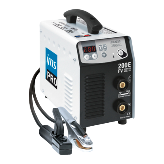
    IMS 200 E FV Der Anwender muss prüfen, ob andere Werkstoffe in der Umgebung benutzt werden können. Weitere Schutzmaßnah- men können dadurch erforderlich sein; h) die Tageszeit, zu der die Schweißarbeiten ausgeführt werden müssen. Die Größe der zu beachtenden Umgebung ist von der Struktur des Gebäudes und der anderen dort stattfindenden Akti- vitäten abhängig.
  • Seite 20 ANSCHLUSS - INBETRIEBNAHME • Die Geräte IMS 200 E FV werden mit einem 16 A CEE7/7. Die IMS 200 E FV verfügen über die «Flexible Voltage» Technologie, die den Anschluss der Geräte an jedes Stromnetz von 100V bis 240V (50-60Hz) ermöglicht. Der aufgenom- mene Strom (I1eff) ist am Gerät aufgedruckt.
  • Seite 21: Wig Kontaktzündung

    IMS 200 E FV 200 E FV HOT START 0 > 90% ARC FORCE Automatic Hinweis: Niedriger Hot Start für dünne Metallbleche; hoher Hot Start für schwer zu schweißende Metalle mit verschmutzen oder oxidierten Stellen. Um Hot Start einzustellen, gehen Sie wie folgt vor: •...
  • Seite 22: Empfohlene Schweißeinstellungen/ Elektrode Schleifen

    IMS 200 E FV Empfohlene Schweißeinstellungen/ Elektrode schleifen Ø Elektrode (mm) Gasströmung Strom (A) Ø Düse (mm) = Ø Zusatzdraht (Argon l/min) 0,5-5 10-130 130-200 Um einen optimalen Schweißverlauf zu gewährleisten, nutzen Sie nur Elektroden, welche nach folgendem Vorbild ges- chliffen wurden: L = 2,5 x d.
  • Seite 23 IMS 200 E FV ADVERTENCIAS - NORMAS DE SEGURIDAD CONSIGNA GENERAL Estas instrucciones se deben leer y comprender antes de toda operación. Toda modificación o mantenimiento no indicado en el manual no se debe llevar a cabo. Todo daño físico o material debido a un uso no conforme con las instrucciones de este manual no podrá atribuírsele al fabricante.
  • Seite 24: Seguridad Eléctrica

    IMS 200 E FV HUMOS DE SOLDADURA Y GAS El humo, el gas y el polvo que se emite durante la soldadura son peligrosos para la salud. Hay que prever una ventilación suficiente y en ocasiones puede ser necesario un aporte de aire. Una máscara de aire puede ser una solución en caso de aireación insuficiente.
  • Seite 25: Emisiones Electromagnéticas

    IMS 200 E FV EMISIONES ELECTROMAGNÉTICAS La corriente eléctrica causa campos electromagnéticos (EMF) localizados al pasar por cualquier conductor. La corriente de soldadura produce un campo electromagnético alrededor del circuito de soldadura y del material de soldadura. Los campos electromagnéticos EMF pueden alterar algunos implantes médicos, como los estimuladores cardíacos. Se deben tomar medidas de protección para personas con implantes médicos.
  • Seite 26 IMS 200 E FV metálico o equivalente para material de soldadura instalado de forma fija. Conviene asegurar la continuidad eléctrica del apantallado sobre toda la longitud. Se recomienda conectar el cable apantallado al generador de soldadura para asegurar un buen contacto eléctrico entre el conducto y la fuente de soldadura.
  • Seite 27 RED ELÉCTRICA - PUESTA EN MARCHA • El equipo incluye una toma de corriente de 230V 16A de tipo CEE7/7. El IMS 200 E FV posee un sistema Flexible Vol- tage que permite utilizar el producto en una instalación eléctrica conectada a tierra entre 110V y 240V (50 - 60 Hz). La corriente efectiva absorbida (I1eff) está...
  • Seite 28 IMS 200 E FV Para ajustar el Hot Start, siga las etapas siguientes: Presione la tecla de selección (5). La inscripción HS (Hot Start) parpadea y luego aparece una cifra. 0 - 90 % Ajuste el porcentaje deseado (indicador (1)) mediante los botones (4).
  • Seite 29 IMS 200 E FV Para un funcionamiento óptimo, debe utilizar un electrodo afilado de la siguiente manera: L = 2,5 x d. ANOMALÍAS, CAUSAS, SOLUCIONES Anomalías Causas Soluciones El aparato no libera corriente y el Espere a que acabe el tiempo de La protección térmica del equipo...
  • Seite 30: Общие Указания

    IMS 200 E FV ПРЕДОСТЕРЕЖЕНИЯ - ПРАВИЛА БЕЗОПАСНОСТИ ОБЩИЕ УКАЗАНИЯ Эти указания должны быть прочтены и поняты до начала сварочных работ. Изменения и ремонт, не указанные в этой инструкции, не должны быть предприняты. Производитель не несет ответственности за травмы и материальные повреждения связанные с несоответствующим...
  • Seite 31: Риск Пожара И Взрыва

    IMS 200 E FV СВАРОЧНЫЕ ДЫМ И ГАЗ Выделяемые при сварке дым, газ и пыль опасны для здоровья. Вентиляция должна быть достаточной, и может потребоваться дополнительная подача воздуха. При недостаточной вентиляции можно воспользоваться маской сварщика-респиратором. Проверьте, чтобы всасывание воздуха было эффективным в соответствии с нормами безопасности.
  • Seite 32: Общие Положения

    IMS 200 E FV ЭЛЕКТРОМАГНИТНЫЕ ИЗЛУЧЕНИЯ Электрический ток, проходящий через любой проводник, вызывает локализованные электромагнитные поля (EMF). Сварочный ток вызывает электромагнитное поле вокруг сварочной цепи и сварочного оборудования. Электромагнитные поля EMF могут создать помехи для некоторых медицинских имплантатов, например электрокардиостимуляторов. Меры безопасности должны быть приняты для людей, носящих медицинские имплантаты.
  • Seite 33: Установка Аппарата

    IMS 200 E FV оплётку к источнику сварочного тока для обеспечения хорошего электрического контакта между шнуром и корпусом источника сварочного тока. b. Техобслуживание аппарата ручной дуговой сварки: аппарат ручной дуговой сварки нужно необходимо периодически обслуживать согласно рекомендациям производителя. Необходимо, чтобы все доступы, люки и...
  • Seite 34 (Питание 100В-240В AC). ПИТАНИЕ - ВКЛЮЧЕНИЕ • Аппарат поставляется с вилкой 230В 16A типа CEE7/7. Аппарат IMS 200 E FV оснащен системой «Flexible Voltage» и питается от электрической установки С ЗАЗЕМЛЕНИЕМ между 110В и 240В (50 - 60 Гц). Эффективное значение...
  • Seite 35 IMS 200 E FV Для настройки Hot Start следуйте по следующим этапам: Нажмите на кнопку (5). Мигает сообщение «HS» (Hot Start), затем появляется цифра. 0 - 90 % Настройте желаемые проценты (индикатор (1)) с помощью кнопок (4). Подтвердите требуемую величину нажатием на кнопку (5).
  • Seite 36 IMS 200 E FV Для оптимального функционирования электрод должен быть заточен следующим образом : L = 2,5 x d. НЕИСПРАВНОСТЬ, ПРИЧИНА, УСТРАНЕНИЕ Неисправности Причины Устранение Аппарат не выдает сварочный Ждите охлаждения в течение Сработала тепловая защита ток, при этом горит желтая...
  • Seite 37: Waarschuwing - Veiligheidsinstructies

    IMS 200 E FV WAARSCHUWING - VEILIGHEIDSINSTRUCTIES ALGEMENE INSTRUCTIES Voor het in gebruik nemen van het product moeten deze instructies gelezen en goed begrepen wor- den. Voer geen wijzigingen of onderhoud uit die niet in de handleiding vermeld staan. Geen enkel lichamelijk letsel of schade, veroorzaakt door het niet naleven van de instructies in deze handleiding, kan verhaald worden op de fabrikant van het apparaat.
  • Seite 38: Elektrische Veiligheid

    IMS 200 E FV LASDAMPEN EN GAS Dampen, gassen en stof uitgestoten tijdens het lassen zijn gevaarlijk voor de gezondheid. Zorg voor voldoende ventilatie, soms is toevoer van verse lucht tijdens het lassen noodzakelijk. Een lashelm met verse luchtaanvoer kan een oplossing zijn als er onvoldoende ventilatie is.
  • Seite 39: Elektromagnetische Emissies

    IMS 200 E FV ELEKTROMAGNETISCHE EMISSIES Elektrische stroom die door een geleider gaat veroorzaakt elektrische en magnetische velden. De lass- troom wekt een elektromagnetisch veld op rondom de laszone en het lasmateriaal. De elektromagnetische velden, EMF, kunnen de werking van bepaalde medische apparaten, zoals pacemakers, verstoren.
  • Seite 40: Installatie Van Het Apparaat

    IMS 200 E FV omhulsel te verzekeren over de hele lengte. De bescherming moet aangekoppeld worden aan de lasstroomvoeding, om er zeker van te zijn dat er een goed elektrisch contact is tussen de geleider en het omhulsel van de lasstroomvoeding.
  • Seite 41 STROOMVOORZIENING - OPSTARTEN • Dit apparaat wordt geleverd met een 230V - 16A aansluiting, type CEE7/7. De IMS 200 E FV is uitgerust met een « Flexible Voltage » systeem, en moet aangesloten worden op een GEAARDE elektrische installatie tussen 100V en 240V (50 - 60 Hz).
  • Seite 42 IMS 200 E FV Om de Hot Start in te stellen, volg de volgende stappen : Druk op de selectie-knop (5). «HS» (Hot Start) knippert, en er verschijnt een nummer. 0 - 90 % Stel het gewenste percentage in (display (1)) met behulp van de knoppen (4).
  • Seite 43 IMS 200 E FV Geadviseerde combinaties / elektrode slijpen Ø Electrode (mm) Ø Buse Débit Courant (A) = Ø fil (mm) (Argon l/mn) (métal d’apport) 0,5-5 10-130 130-200 Gebruik, voor een optimaal gebruik, een elektrode die als volgt geslepen is : L = 2,5 x d.
  • Seite 44: Istruzioni Generali

    IMS 200 E FV AVVERTENZE - AVVERTENZE DI SICUREZZA ISTRUZIONI GENERALI Queste istruzioni devono essere lette e comprese prima dell’uso. Ogni modifica o manutenzione non indicata nel manuale non deve essere effettuata. Ogni danno fisico o materiale dovuto ad un uso non conforme alle istruzioni presenti in questo manuale non potrà essere considerata a carico del fabbricante.
  • Seite 45: Sicurezza Elettrica

    IMS 200 E FV FUMI DI SALDATURA E GAS I fumi, gas e polveri emesse dalla saldatura sono pericolosi per la salute. È necessario prevedere una ventilazione sufficiente e a volte è necessario un apporto d’aria. Una maschera ad aria fresca potrebbe essere una soluzione in caso di aerazione insufficiente.
  • Seite 46: Emissioni Elettromagnetiche

    IMS 200 E FV EMISSIONI ELETTROMAGNETICHE La corrente elettrica passando attraverso a qualunque conduttore prodotto dai campi elettrici e magne- tici (EMF) localizzati. La corrente di saldatura produce un campo elettromagnetico attorno al circuito di saldatura e al dispositivo di saldatura.
  • Seite 47: Consigli Sui Metodi Di Riduzione Delle Emissioni Elettromagnetiche

    IMS 200 E FV CONSIGLI SUI METODI DI RIDUZIONE DELLE EMISSIONI ELETTROMAGNETICHE a. Rete pubblica di alimentazione: conviene collegare il materiale di saldatura all’arco a una rete pubblica di ali- mentazione secondo le raccomandazioni del fabbricante. Se ci sono interferenze, potrebbe essere necessario prendere misure di prevenzione supplementari, come il filtraggio della rete pubblica di rifornimento [elettrico].
  • Seite 48 ALIMENTAZIONE - ACCENSIONE Il dispositivo è fornito con una presa da 230V 16A di tipo CEE7/7. Il IMS 200 E FV, provvisto di un sistema «Flexible Voltage», è alimentato grazie ad una installazione elettrica con messa a terra tra 110V e 240V (50 - 60 Hz). La corrente effettiva assorbita (I1eff) è...
  • Seite 49 IMS 200 E FV - Regolare l’intensità desiderata (display(1)) per mezzo dei tasti (4). 200 E FV HOT START 0 > 90% ARC FORCE Automatique Conseils : Hot start debole, per le lamiere sottili – Hot start elevato per i metalli difficili da saldare (pezzi sudici o ossidati) Per regolare l’...
  • Seite 50 IMS 200 E FV Combinazioni consigliate / affilatura elettrodo Ø Elettrodo (mm) = Ø filo Ø Ugello Flusso Corrente (A) (metallo d’appor- (mm) (Argon l/mn) 0,5-5 10-130 130-200 Per funzionare nelle migliori condizioni l’elettrodo deve essere affilato come segue: L = 2,5 x d.
  • Seite 51 IMS 200 E FV PIÈCES DE RECHANGE / SPARE PARTS / ERSATZTEILE / PIEZAS DE REPUESTO / ЗАПАСНЫЕ ЧАСТИ / RESERVE ONDERDELEN / PEZZI DI RICAMBIO DÉSIGNATION 200 E FV 51469 Douilles / Connectors / Schweißbuchsen / Conectores / Коннекторы / Fitting / Connettori 51914 Clavier / Display / Anzeige / Teclado / Дисплей...
  • Seite 52 IMS 200 E FV SCHÉMA ÉLECTRIQUE / CIRCUIT DIAGRAM /SCHALTPLAN/ DIAGRAMA ELECTRICO /ЭЛЕКТРИЧЕСКАЯ СХЕМА / ELEKTRISCHE SCHEMA / SCEMA ELETTRICO 51914...
  • Seite 53 IMS 200 E FV INTERFACE / INTERFACE / SCHNITTSTELLE / INTERFAZ / ИНТЕРФЕЙС / INTERFACE / INTERFACCIA Afficheur / Display / Anzeige / Indicador / Индикатор / Display / Display Voyant mode « soudage à l’électrode » (MMA) / Mode indicator « electrode welding »...
  • Seite 54: Herstellergarantie

    IMS 200 E FV CONDITIONS DE GARANTIE FRANCE La garantie couvre tous défauts ou vices de fabrication pendant 2 ans, à compter de la date d’achat (pièces et main d’oeuvre). La garantie ne couvre pas : • Toutes autres avaries dues au transport.
  • Seite 55 IMS 200 E FV GARANTIE De garantie dekt alle gebreken en fabricagefouten gedurende twee jaar vanaf de aankoopdatum (onderdelen en arbeidsloon). De garantie dekt niet : • Alle overige schade als gevolg van vervoer. • De gebruikelijke slijtage van onderdelen (Bijvoorbeeld : kabels, klemmen, enz.).
  • Seite 56 IMS 200 E FV SPÉCIFICATIONS TECHNIQUES / TECHNICAL SPECIFICATIONS / TECHNISCHE DATEN / ESPECIFICACIONES TÉCNICAS / ТЕХНИЧЕСКИЕ СПЕЦИФИКАЦИИ / TECHNISCHE GEGEVENS / SPECIFICHE TECNICHE 200 E FV Primaire / Primary / Primär / Primario / Первичка / Primaire / Primario / Podstawowy Tension d’alimentation / Power supply voltage / Stromversorgung / Tensión de red eléctrica / Напряжение...
  • Seite 57 IMS 200 E FV *Los ciclos de trabajo están realizados en acuerdo con la norma EN60974-1 a 40ºC y sobre un ciclo de diez minutos. Durante un uso intensivo (superior al ciclo de trabajo), se puede activar la protección térmica. En este caso, el arco se apaga y el indicador se enciende.
  • Seite 58 IMS 200 E FV - Courant d’alimentation assigné maximal (valeur efficace) - Rated maximum supply current (effective value) - Maximaler Versorgungsstrom (Effektivwert) - Corriente maxima de alimentacion de la red - Максимальный сетевой ток (эффективная I1max мощность) - Maximale nominale voedingsstroom (effectieve waarde) - Corrente d’alimentazione nominale massima (valore effettivo) - Courant d’alimentation effectif maximal - Maximum effective supply current - Maximaler tatsächlicher Versorgungsstrom...
  • Seite 59 IMS 200 E FV - Nombre d’électrodes normalisées soudables en 1 heure, à 20°C, avec un temps d’arrêt de 20 s. entre chaque électrode - Number of standardized electrodes weldable during 1 hour at 20°C, with a delay of 20 s. between each electrode. - Anzahl der Standard-Elektroden, die in 1 Stunde bei 20°C geschweißt werden können mit einer Pause von 20 s zwischen jeder Elektrode...
  • Seite 60 JBDC 1, rue de la Croix des Landes CS 54159 53941 SAINT-BERTHEVIN Cedex France...

Inhaltsverzeichnis