ZENEC ZE-RVSC150MV Montageanleitung
Verfügbare Sprachen
Verfügbare Sprachen
MOUNTING INSTRUC TIONS
12 V > 5.5 V Step-down converter
and TTL controller board
KEY FEATURES
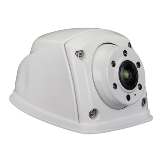
• Compact universal "multi-view" rear view camera for use with selected,
multi-view control compatible ZENEC device models
• Multi-view function offering six camera image display modes, selectable via
touchscreen of ZENEC device (normal, top-down, panorama, L/R blind-spot,
2-split-screen, triple split-screen)
• High quality CMOS picture sensor with low power consumption, for detailed
high contrast cam image
• IR LED lighting with 5 LEDs and dynamic brightness control via LDR
element
• Robust white painted die-cast aluminum housing with mechanical
adjustment of vertical image section
• 15 m long separable system cable equipped with mini 4-PIN connectors
• IP68 certified
CAUTION
Use the included connection cable exclusively. Modifying the cable will
void your warranty.
The camera is water- and dustproof and has been licensed according
to the international standard IP68. However, vehicle cleaning using high
pressure water and steam jet devices may still lead to damage of IP68
rated camera models by intrusion of water.
If the motorhome is treated with a water jet high pressure cleaning device,
make sure to keep a distance of at least one meter between the water
nozzle and the camera sensor / housing.
INSTALLATION
The ZE-RVSC150MV is mounted in the center rear of the vehicle with
the sensor pointing downwards. The camera sensor cannot be adjusted
mechanically. For an optimal image viewing eld, the camera sensor
should be about 220 to 265 cm above the ground.
Determine the approximate desired mounting location for the camera.
If you look at the foot area of the camera, you will see three through
mounting holes for the mounting screws in the rubber base and the
metal base – with a diameter of about 5mm, as well as a larger center
feed-through hole for the camera cable.
Pull the rubber foot off the camera body and use it as a template to
mark the mounting holes and cable entry. Ensure that there is adequate
accessible space on the back of the mounting surface for inserting/pull-
ing/routing the camera cable. Mark the holes with an Edding pen. The
mounting holes for the three self-tapping metal screws must be drilled
with a 3.5 mm metal drill, the hole for the cable entry with a 7.5 mm metal
UK Declaration of Conformity
Hereby, ACR Brändli + Vögeli AG declares that ZENEC
ZE-RVSC150MV is CE compliant – the EU Declaration
of Conformity can be accessed via the following Internet
address:
http://www.zenec.com
Conformity Documents" in the footer area of the page).
ZENEC by ACR AG ∙ Bohrturmweg 1 ∙ CH-5330 Bad Zurzach ∙ Switzerland, EU Legal Representative: ACR S & V GmbH ∙ Industriestr. 35 ∙ D-79787 Lauchringen ∙ Germany ∙ www.zenec.com
+12V (male bullet)
GND (male bullet)
Video (CVBS) RCA
MV data line
(6.3 x 0.8 mm male spade connector)
MALE
(see link „Product
MULTIVIE W RE AR VIE W C AMER A FOR MOTORHOMES
FEMALE
Original Connection
TECHNICAL SPECIFICATIONS
Image device:
Horizontal view angle:
TV system:
Effective sensor resolution:
Resolution of video-out signal: 700 TV lines
Frame rate:
Signal to noise ratio:
Light sensitivity:
Video output:
Electronic shutter:
White balance:
Automatic gain control:
Backlight compensation:
Power supply:
Current consumption:
IP protection rating:
Operating temperature:
Dimensions L x W x H
drill. Vacuum out the metal shavings and seal the drill holes with some
lacquer or paint.
Disassemble the camera using the Allen key included in the kit to remove
the rear case. Press the rubber foot back onto the camera base. Feed
the camera cable into the drilled hole in the middle and carefully screw
down the camera with the three self-tapping metal screws included
in the set. Align the camera vertically – tighten the screws snugly and
reattach the back of the camera to the camera main body with sensor
using the four Allen screws. Now lay the 15 m long extension cable from
the mounting location of the camera to the device mounting slot in the
dashboard.
Connect the camera's video RCA plug, the multi-view data line and the
power supply cable to the designated connections of the head unit. Do
a camera test run.
ZE-RVSC150MV
ZE-RVSC150MV
1/3" / 8.51 mm Pixelplus
PC1058C CMOS Sensor
180° (max.) - image areas
controllable via ZENEC device
NTSC / 30 fps
960(H) x 576(V) pixels
30 fi elds/sec.
43.3 dB
1.0 Lux, 0 Lux with IR-ON
1.0 Vp-p (+/-0.2 V), 75 ohms,
CVBS
auto
auto
auto
auto
5.5 – 12 VDC
1,200 mW (220±5 mA@5.5 V
via step-down converter)
IP68
-20°C~+70° C
:
74 x 54 x 44 mm
UK Authorised Representative
(for authorities only)
ProductIP (UK) Ltd.
8, Northumberland Av.
London WC2N 5BY

Verwandte Anleitungen für ZENEC ZE-RVSC150MV


Inhaltszusammenfassung für ZENEC ZE-RVSC150MV
- Seite 2 Internetadresse abgerufen werden: https://www.zenec.com (siehe Link „Dokumente zur Produktkonformität“ im Fussbereich). ZENEC by ACR AG Bohrturmweg 1 CH-5330 Bad Zurzach Schweiz, Gesetzlicher Vertreter EU: ACR S & V GmbH Industriestr. 35 D-79787 Lauchringen Deutschland www.zenec.com...