Herunterladen Inhalt Inhalt Diese Seite drucken
Inhaltsverzeichnis

Werbung

Verfügbare Sprachen

Verfügbare Sprachen

Istruzioni per installazione, uso e manutenzione
Montage und Bedienungsanleitung
Instructions pour installation, utilisation et entretien
Installation, use and maintenance instructions
Bruciatori di gas ad aria soffiata
I
Gas-Gebläsebrenner
D
Brûleurs gaz à air soufflé
F
Forced draught gas burners
GB
Funzionamento bistadio
Zweistufiger Betrieb
Fonctionnement à 2 allure
Two stage operation
CODICE - CODE
3761618
3761718
3761818
MODELLO - MODELL - MODELE
MODEL
BS2D TL
BS3D TL
BS4D TL
TIPO - TYP - TYPE
916 T1
917 T1
918 T1
2903115 (6) - 11/2015

Werbung

Inhaltsverzeichnis
loading

Inhaltszusammenfassung für Riello BS2D TL

  • Seite 1 Zweistufiger Betrieb Fonctionnement à 2 allure Two stage operation MODELLO - MODELL - MODELE CODICE - CODE TIPO - TYP - TYPE MODEL 3761618 BS2D TL 916 T1 3761718 BS3D TL 917 T1 3761818 BS4D TL 918 T1 2903115 (6) - 11/2015...
  • Seite 3 Dichiarazione del costruttore RIELLO S.p.A. dichiara che i seguenti prodotti rispettano i valori limite di emissione di NOx imposti dalla normativa tedesca “1. BImSchV revisione 26.01.2010”. Prodotto Tipo Modello Potenza 35/40 ÷ 91 kW Bruciatori di gas ad aria soffiata...
  • Seite 4 Déclaration du constructeur RIELLO S.p.A. déclare que les produits suivants respectent les valeurs limite d'émission de NOx imposés par la norme alle- mande «1. BImSchV revision 26.01.2010». Produit Type Modèle Puissance 35/40 ÷ 91 kW Brûleurs gaz à air soufflé...
  • Seite 5: Inhaltsverzeichnis

    INDICE DESCRIZIONE DEL BRUCIATORE ..........1.1 Materiale a corredo .
  • Seite 6: Descrizione Del Bruciatore

    DESCRIZIONE DEL BRUCIATORE Bruciatore di gas con funzionamento bistadio. ➤ Il bruciatore risponde al grado di protezione IP X0D (IP 40) secondo EN 60529. ➤ Marcatura CE secondo Direttiva Gas 2009/142/CE; PIN 0085AQ0409. Conforme alle Direttive: Compatibilità Elettromagnetica 2004/108/CE, Bassa Tensione 2006/95/CE e Macchine 2006/42/CE.
  • Seite 7: Dati Tecnici

    DATI TECNICI DATI TECNICI TIPO 916 T1 917 T1 918T1 ÷ ÷ 65/75 ÷ 190 35/40 110/140 Potenza termica (1) secondo EN 676 55,9/64,5 ÷ 163,4 30,1/34,4 ÷ 78,2 94,6/120,4 ÷ 215 Mcal/h ÷ ÷ Pci: 8 12 kWh/m = 7000 10.340 kcal/m Gas naturale (Famiglia 2) Pressione: min.
  • Seite 8: Campi Di Lavoro

    CAMPI DI LAVORO 916T1 D8953 kcal/h 30.000 40.000 50.000 60.000 70.000 80.000 Potenza termica 918T1 917T1 D8832 kcal/h Potenza termica Nel modello BS4D tipo 918T1, per garantire il funzionamento con una potenzialità da 220 - 250 kW, togliere il fonoassorbente pre- tranciato per liberare le feritoie addizionali di ingresso d’aria sul cofano.
  • Seite 9: Installazione

    CORRELAZIONE TRA PRESSIONE DEL GAS E POTENZIALITÀ Per avere la massima potenzialità occorrono 9,3 mbar, relativamente al modello 916T1, misurati al manicotto (M2, vedi cap. 3.6, pag. 7) con camera di combustione a 0 mbar e gas G20 – Pci = 10 kWh/m 3 (8.570 kcal/m 3 ). D8952 kcal/h 150.000...
  • Seite 10: Fissaggio Alla Caldaia

    FISSAGGIO ALLA CALDAIA Per installare il bruciatore alla caldaia è necessario effettuare le seguenti operazioni: ➤ Allargare, se necessario, i fori dello schermo isolante (3, fig. 3). Fissare alla portina della caldaia (1) la flangia (5) mediante le quattro viti (4) e (se necessario) i dadi (2) ➤...
  • Seite 11: Rampa Gas

    RAMPA GAS, (secondo EN 676) La rampa gas viene fornita a parte e per la sua regolazione vedere le istruzioni che l’accompagnano. RAMPA GAS ATTACCHI BRUCIATORE IMPIEGO ABBINABILE TIPO CODICE INGRESSO USCITA MB ZRDLE 405 B01 3970540 BS2D Rp 3/4 Flangia 2 Gas naturale e GPL MB ZRDLE 407 B01...
  • Seite 12: Collegamenti Elettrici

    COLLEGAMENTI ELETTRICI LEGENDA SO – Sonda ionizzazione B5 – Segnalazione funz. 2° – Spia blocco stadio (230V - 0,5 A max) T6A – Fusibile – Condensatore TB – Terra bruciatore CN1 – Connettore sonda – Termostato limite – Elettrodo TR – Termostato di regolazione –...
  • Seite 13: Funzionamento

    FUNZIONAMENTO REGOLAZIONE DELLA COMBU- STIONE In conformità con la Direttiva Rendimento 92/42/CEE, l’applicazione del bruciatore alla caldaia, la regolazione e il collaudo, devono es- sere eseguiti nell’osservanza del manuale d’istruzione della caldaia stessa, compreso il controllo della concentrazione di CO e CO fumi, della loro temperatura e di quella media dell’acqua della caldaia.
  • Seite 14: Regolazione Serranda Aria

    REGOLAZIONE SERRANDA ARIA, (fig. 10) Fig. 10 Il primo avviamento deve sempre essere effettuato, agendo sulla vite (12), in modo che l’indice della posizione serranda aria di 1° stadio sia superiore a tacca 1, (taratura di fabbrica tacca 1). Per effettuare la regolazione procedere come segue: ➤...
  • Seite 15: Pressostato Aria

    PRESSOSTATO ARIA Eseguire la regolazione del pressostato aria dopo aver effettuato tutte le altre regolazioni del bruciatore con il pressostato aria regolato a inizio scala. Con il bruciatore funzionante alla potenza richiesta, ruotare la manopola lentamente in senso orario fino al blocco del bruciatore. Ruotare quindi in senso antiorario la manopola di una tacca e ripetere l’avviamento del bruciatore per verificarne la regolarità.
  • Seite 16: Manutenzione

    MANUTENZIONE Prima di effettuare qualsiasi operazione di pulizia o controllo, togliere líalimentazione elettrica al bru- ciatore agendo sullíinterruttore generale dellíimpianto e chiudere la valvola di intercettazione del gas. Il bruciatore richiede una manutenzione periodica, che deve essere eseguita da personale abilitato e in con- formità...
  • Seite 17: Anomalie / Rimedi

    SEGNALE CAUSA PROBABILE Pressostato aria di minima non chiude o è già chiuso prima della chiusura del termostato limite: 3 lampeggi – guasto al pressostato aria; – pressostato aria non regolato; Luce presente in camera prima dell’accensione e allo spegnimento del bruciatore: 4 lampeggi –...
  • Seite 18 ANOMALIE POSSIBILE CAUSA RIMEDIO È invertito il collegamento fase-neutro. Provvedere ad un loro scambio. Manca o è inefficace il collegamento Provvedere a renderlo efficiente. Il bruciatore esegue di terra. normalmente il ciclo di Verificare la corretta posizione ed even- La sonda di ionizzazione è a massa o preventilazione ed ac- tualmente aggiustarla secondo quanto non è...
  • Seite 19: Anomalie In Funzionamento

    ANOMALIE POSSIBILE CAUSA RIMEDIO Ripristinare il corretto rapporto massimo di Rapporto di potenzialità tra 1° e 2° sta- 1:2 controllando che la potenzialità del 1° I l b r u c i t o r e t e n d e a dio superiore a 1:2.
  • Seite 20: Avvertenze E Sicurezza

    AVVERTENZE E SICUREZZA Al fine di garantire una combustione col minimo tasso di emissioni inquinanti, le dimensioni ed il tipo di ca- mera di combustione del generatore di calore, devono corrispondere a valori ben definiti. È pertanto consigliato consultare il Servizio Tecnico di Assistenza prima di scegliere questo tipo di brucia- tore per l’abbinamento con una caldaia.
  • Seite 21 INHALT BESCHREIBUNG DES BRENNERS ..........1.1 Mitgeliefertes Zubehör .
  • Seite 22: Beschreibung Des Brenners

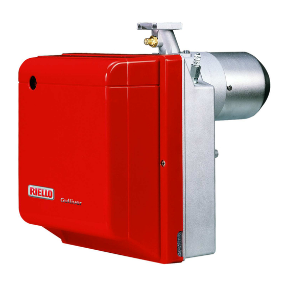
    BESCHREIBUNG DES BRENNERS Gasbrenner mit zweistufigem Betrieb. Der Brenner entspricht dem Schutzart IP X0D (IP 40) gemäß EN 60529. ➤ ➤ CE Kennzeichnung gemäß der Gasgeräterichtlinie 2009/142/EG; PIN 0085AQ0409. Gemäß Richtlinien: Elektromagnetische Verträglichkeit 2004/108/EG, Niederspannungsrichtlinie 2006/95/EG und Maschinenrichtlinie 2006/42/EG. ➤ Gasstrecke gemäß...
  • Seite 23: Technische Merkmale

    TECHNISCHE MERKMALE 2.1 TECHNISCHE DATEN 916 T1 917 T1 918T1 ÷ ÷ 65/75 ÷ 190 35/40 110/140 Brennerleistung (1) nach EN 676 55,9/64,5 ÷ 163,4 30,1/34,4 ÷ 78,2 94,6/120,4 ÷ 215 Mcal/h ÷ ÷ Unterer Heizwert: 8 12 kWh/m = 7000 10.340 kcal/m Erdgas (Familie 2) Anschlussdruck: Min.
  • Seite 24: Arbeitsfelder

    ARBEITSFELDER 916T1 D8953 kcal/h 30.000 40.000 50.000 60.000 70.000 80.000 Brennerleistung 918T1 917T1 D8832 kcal/h Brennerleistung In dem Modell BS4D Typ 918T1, um den Betrieb für eine Leistung vom ÷ 250 kW zu gewähren, die geschnittene Gerauschdämmung weg- nehmen, so werden die zusätzlichen Schlitze des Lufteingangs auf der Verkleidung frei gemacht.
  • Seite 25: Vom Gasdruck Am Brennerkopf Abhängige Brennerleistung

    VOM GASDRUCK AM BRENNERKOPF ABHÄNGIGE BRENNERLEISTUNG Bei einem an dem Verbindungsrohr (M2, siehe Kap. 3.6, Seite 7) gemessenen Druck von 9,3 mbar, hinsichtlich des Modells 916T1, mit einem feuerraumseitigen Druck von 0 mbar und mit Gas G20 - unterer Heizwert = 10 kWh/m (8.570 kcal/m ), erreicht man die Höchstleistung.
  • Seite 26: Brennermontage

    3.2 BRENNERMONTAGE Zur Installation des Brenners am Heizkessel sind folgende Vorgänge auszuführen: ➤ Falls erforderlich, die Bohrungen der Isolierdichtung (3, Abb. 3) erweitern. ➤ Mit den Schrauben (4) (falls erforderlich) den Muttern (2) an der Kesseltür (1) den Flansch (5) mit Iso- lierdichtung (3) montieren, aber eine der zwei höheren Schrauben losschrauben (siehe Abb.
  • Seite 27: Gasstrecken

    3.4 GASSTRECKEN, (nach EN 676) Die Gasstrecke muß der Euronorm EN 676 entsprechen und wird extra bestellt. Die Einregulierung wird entsprechend der beigefügten Betriebsanleitung durchgeführt. GASSTRECKE ABGESTIMM- ANSCHLÜSSE GEBRAUCH CODE EINGANG AUSGANG BRENNER MB ZRDLE 405 B01 3970540 BS2D Rp 3/4 Flansch 2 Erdgas und Flüssiggas MB ZRDLE 407 B01...
  • Seite 28: Elektrisches Verdrahtungsschema

    3.7 ELEKTRISCHES VERDRAHTUNGSSCHEMA ZEICHENERKLÄRUNG – 2. Stufe Betrieb-Fern- – Störabschaltung-Fern- meldung meldung – Kondensator (230V - 0,5A max.) CN1 – Verbinder Fühler T6A – Sicherung – Zündelektrode TB – Brenner-Erdung – Stufe Stundenzähler – Grenzthermostat MV – Motor – Thermostateinstellung PA –...
  • Seite 29: Betrieb

    BETRIEB 4.1 EINSTELLUNG DER BRENNER- LEISTUNG In Konformität mit der Wirkungsgradrichtlinie 92/ 42/EWG müssen die Anbringung des Brenners am Heizkessel, die Einstellung und die Inbetrieb- nahme unter Beachtung der Betriebsanleitung des Heizkessels ausgeführt werden, einschließ- lich Kontrolle der Konzentration von CO und in den Abgasen, der Abgastemperatur und der mittlenen Kesseltemperatur.
  • Seite 30: Luftklappeneinstellung

    LUFTKLAPPENEINSTELLUNG, (Abb. 10) Abb. 10 Das erste Anfahren muss immer durch Betätigung der Schraube (12) erfolgen, so dass der Stellungszeiger der Luftklappe in der 1. Stufe über Kerbe 1 ist (werkseitige Einstellung von Kerbe 1). Für die Einstellung ist wie folgt vorzugehen: ➤...
  • Seite 31: Luftdruckwächter

    4.5 LUFTDRUCKWÄCHTER Während der Einregulierung des Gasbrenners wird der Luftdruckwächter auf 0 gestellt. Ist die Einregulierung abgeschlossen, wird der Luftdruck einreguliert. Die Regulierskala langsam im Uhrzeigersinn drehen bis der Brenner auf Störung schaltet. Dann die Regulierskala entgegengesetzt um eine Skalenmarkierung zurückdre- hen und den Brenner wieder entstören.
  • Seite 32: Wartung

    WARTUNG Vor der Durchführung von Reinigungs- oder Kontrollarbeiten, immer die elektrische Versorgung zum Brenner durch Betätigung des Hauptschalters der Anlage abschalten und das Gasabsperrven- til schließen. Der Brenner bedarf regelmäßiger Wartung, die von autorisiertem Personal und in Übereinstimmung mit ört- lichen Gesetzen und Vorschriften ausgeführt werden muss.
  • Seite 33: Störungen / Abhilfe

    SIGNAL MÖGLICHE URSACHE Minimalluftdruckwächter schließt nicht oder ist vor dem Schließen des Begrenzungsthermostaten bereits geschlossen: 3 Blinken – Defekt am Luftdruckwächter; – Luftdruckwächter schlecht eingestellt. Licht in der Brennkammer vor dem Einschalten und beim Ausschalten des Brenners: 4 Blinken – Vorhandensein von Fremdlicht vor oder nach der Umschaltung des Begrenzungsthermostaten;...
  • Seite 34 STÖRUNGEN MÖGLICHE URSACHE ABHILFE Der Anschluss Phase - Nulleiter ist Umpolen. verwechselt. Kein oder unwirksames Erdungskabel. Instand setzen. Der Brenner führt den Vorbelüftungs- und Gemäß den Angaben dieser Anleitung Der Ionisationsfühler hat eine Kurz- Zündzyklus regulär aus; den richtigen Lage prüfen und den Ioni- schluß...
  • Seite 35: Betriebsstörungen

    STÖRUNGEN MÖGLICHE URSACHE ABHILFE Korrektes max. Verhältnis von 1:2 wieder Leistungsverhältnis zwischen 1. und herstellen und prüfen, dass die Leistung Der Brenner neigt zum 2. Stufe über 1:2. der 1. Stufe nicht unter dem Minimum Abreißen der Flamme des Regelbereichs ist. beim Übergang von 1.
  • Seite 36: Hinweise Und Sicherheit

    HINWEISE UND SICHERHEIT Um bestmögliche Verbrennungs-Ergebnisse sowie niedrige Emissionswerte zu erzielen, muß die Brenn- kammer-Geometrie des Heizkessels für den Brenner geeignet sein. Deshalb ist es notwendig, vor Einsatz des Brenners Informationen bei einzuholen, um ein einwandfreies Funktionieren des Brenners zu gewährleisten. Dieser Brenner darf nur für den Einsatzzweck verwendet werden, für den er hergestellt wurde.
  • Seite 37 SOMMAIRE DESCRIPTION DU BRULEUR ..........1.1 Matériel fourni .
  • Seite 38: Description Du Bruleur

    DESCRIPTION DU BRULEUR Brûleur gaz fonctionnement à deux allures. ➤ Brûleur conforme au degré de protection IP X0D (IP 40) selon EN 60529. Marquage CE conforme à la Directive Appareils à Gaz 2009/142/CE; PIN 0085AQ0409. ➤ Conforme à les Directives: Compatibilité Électromagnétique 2004/108/CE, Basse Tension 2006/95/CE et Machines 2006/42/CE.
  • Seite 39: Donnees Techniques

    DONNEES TECHNIQUES 2.1 DONNEES TECHNIQUES TYPE 916 T1 917 T1 918T1 ÷ 65/75 ÷ 190 35/40 ÷ 91 110/140 Puissance thermique 55,9/64,5 ÷ 163,4 (1) selon EN 676 30,1/34,4 ÷ 78,2 94,6/120,4 ÷ 215 Mcal/h ÷ ÷ Pci: 8 12 kWh/m = 7000 10.340 kcal/m Gaz naturel (Famille 2)
  • Seite 40: Plage De Travail

    PLAGES DE TRAVAIL 916T1 D8953 kcal/h 30.000 40.000 50.000 60.000 70.000 80.000 Puissance thermique 918T1 917T1 D8832 kcal/h Puissance thermique Dans le modèle BS4D type 918T1, pour garantir le fonctionne- ÷ ment avec une puissance de 220 250 kW, enlever l’insonorisant pré-découpé...
  • Seite 41: Installation

    CORRELATION ENTRE PRESSION DU GAZ ET PUISSANCE Pour obtenir la puissance maxi, il faut avoir 9,3 mbar, relativement au modèle 916T1, mesurée au manchon (M2, voir chapitre 3.6, page 7) avec chambre de combustion à 0 mbar et gaz G20 - Pci = 10 kWh/m 3 ( 8.570 kcal/m 3 ) .
  • Seite 42: Fixation À La Chaudière

    3.2 FIXATION A LA CHAUDIERE Pour installer le brûleur à la chaudière, il et nécessaire d’effectuer les opérations suivantes: Agrandir, si nécessaire, les trous du joint isolant (3, fig. 3). ➤ ➤ Fixer la bride (5) sur la plaque de la chaudière (1) à l’aide des quatre vis (4) et (si nécessaire) des écrous (2) en interposant le joint isolant (3) mais en ne serrant pas complètement l’une des deux vis supérieures (4), (voir fig.
  • Seite 43: Rampe Gaz

    3.4 RAMPE GAZ, (selon EN 676) La rampe gaz est fournie à part, voir les notices jointes pour son réglage. RAMPE GAZ CONNEXIONS BRULEUR EMPLOI D’UTILISATION TYPE CODE ENTREE SORTIE MB ZRDLE 405 B01 3970540 BS2D Rp 3 / 4 Bride 2 Gaz naturel et GPL MB ZRDLE 407 B01...
  • Seite 44: Installation Électrique

    3.7 INSTALLATION ELECTRIQUE LEGENDE – Signalis. de fonction. – Signalisation de sécu- 2 ème allure rité à distance – Condensateur (230V - 0,5 A max.) CN1 – Connecteur sonde T6A – Fusible – Electrode TB – Terre brûleur – Compteur horaire –...
  • Seite 45: Fonctionnement

    FONCTIONNEMENT 4.1 REGLAGE DE LA COMBUSTION Conformément à la Directive rendement 92/42/CEE, suivre les indications du manuel de la chaudière pour monter le brûleur, effectuer le réglage et l’essai, contrôler la concentration de CO et CO , dans les fumées, leur température et celle moyenne de l’eau de la chaudière.
  • Seite 46: Réglage Volet D'air

    REGLAGE VOLET D'AIR, (fig. 10) Fig. 10 Le premier démarrage doit toujours être effectué en agissant sur la ère vis (12), de façon à ce que le repère de la position volet d’air de 1 allure soit supérieur à l’encoche 1 (réglage en usine encoche 1). Procéder comme suit pour effectuer le réglage: ème ➤...
  • Seite 47: Pressostat Air

    4.5 PRESSOSTAT AIR Régler le pressostat air après avoir effectué tous les autres réglages du brûleur avec le pressostat air réglé en début d’échelle. Avec le brûleur fonctionnant à la puissance désirée, tourner lentement le bouton gra- dué dans le sens des aiguilles d’une montre jusqu’à l’arrêt du brûleur. Tourner ensuite ce même bouton d’une graduation dans le sens inverse et répéter le démarrage du brûleur pour vérifier le bon fonctionne- ment.
  • Seite 48: Entretien

    ENTRETIEN Avant d’effectuer une opération de nettoyage ou de contrôle quelconque, couper le courant du brûleur en agissant sur l’interrupteur général de l’installation et fermer la vanne d’arrêt du gaz. Le brûleur nécessite d’un entretien périodique qui doit être effectué par du personnel expérimenté, en se conformant aux lois et aux normes locales.
  • Seite 49: Anomalies / Remedes

    SIGNAL CAUSE PROBABLE Le pressostat air minimum ne se ferme pas ou est déjà fermé avant la ferme- ture du thermostat limite: 3 impulsions – anomalie du pressostat air; – pressostat air pas réglé. Flamme présente dans la chambre avant l’allumage et lorsque le brûleur s’éteint: 4 impulsions –...
  • Seite 50 ANOMALIES CAUSES POSSIBLES REMEDES Inversion phase / neutre Procéder au changement. Mauvais raccordement à la terre Faire un raccordement correct. Le brûleur effectue nor- malement son cycle de Vérifier la position et la corriger si néces- La sonde d'ionisation est à la préventilation et d'allu- saire, en se réferent a la notice.
  • Seite 51: Anomalies Durant Le Fonctionnement

    ANOMALIES CAUSES POSSIBLES REMEDES La pression du gaz en réseau est très proche de la valeur a la- quelle le pressostat gaz est ré- glé. La baisse de pression qu'il y a à Le brûleur répète en l'ouverture de la vanne, provoque continu le cycle de dé- l'ouverture du pressostat.
  • Seite 52: Conseils Et Sécurité

    CONSEILS ET SÉCURITÉ Afin de garantir une combustion avec le taux minimum des émissions polluantes, les dimensions et le type de chambre de combustion du générateur doivent correspondre à des valeurs bien déterminées. Il est donc conseillé de consulter le Service Technique avant de choisir ce type de brûleur pour l’équipement d’une chaudière.
  • Seite 53 INDEX BURNER DESCRIPTION ............1.1 Burner equipment .
  • Seite 54: Burner Description

    BURNER DESCRIPTION Two stage gas burner. The burner meets protection level of IP X0D (IP 40) as EN 60529. ➤ ➤ CE marking according to Gas Appliance Directive 2009/142/EC; PIN 0085AQ0409. According to Directives: Electromagnetic Compatibility 2004/108/EC, Low Voltage 2006/95/EC and Machines 2006/42/EC.
  • Seite 55: Technical Data

    TECHNICAL DATA 2.1 TECHNICAL DATA TYPE 916 T1 917 T1 918T1 35/40 – 91 65/75 – 190 110/140 – 250 Thermal power (1) as EN 676 55.9/64.5 – 163.4 94.6/120.4 – 215 Mcal/h 30.1/34.4 – 78.2 Net heat value: 8 – 12 kWh/m 3 = 7000 –...
  • Seite 56: Firing Rate

    FIRING RATES 916T1 D8953 kcal/h 30,000 40,000 50,000 60,000 70,000 80,000 Thermal power 918T1 917T1 D8832 kcal/h Thermal power In the BS4D model type 918T1, in order to guarantee the working with an output of 220 - 250 kW, remove the blank deadening to free the supplementary slits of the air inlet on the cover.
  • Seite 57: Installation

    CORRELATION BETWEEN GAS PRESSURE AND BURNER OUTPUT To obtain the maximum output, a gas head pressure of 9.3 mbar, relatively to 916T1 model, is measured (M2, see chapter 3.6, page 7) with the combustion chamber at 0 mbar using gas G20 with a net heat value of 10 kWh/m (8.570 kcal/m D8952...
  • Seite 58: Boiler Fixing

    3.2 BOILER FIXING To fit the burner to the boiler it is necessary to carry out the following: ➤ Widen, if necessary, the insulating gasket holes (3, fig. 3). ➤ Fix the flange (5) to the boiler door (1) using four screws (4) and (if necessary) the nuts (2) interposing the insulating gasket (3) but keep unloosing one of the two upper screws (4) (see fig.
  • Seite 59: Gas Train

    3.4 GAS TRAIN, (as EN 676) The gas train is supplied separately, for its adjustment see the enclosed instructions. GAS TRAIN CONNECTIONS MATCHED BURNER TYPE CODE INLET OUTLET MB ZRDLE 405 B01 3970540 BS2D Rp 3/4 Flange 2 Natural gas and LPG MB ZRDLE 407 B01 3970538 BS2D...
  • Seite 60: Electrical Wiring

    3.7 ELECTRICAL WIRING KEY TO LAY-OUT – 2 nd stage working signal – Lock-out signal – Capacitor (230V - 0.5A max.) CN1 – Ionisation probe T6A – Fuse connector TB – Burner-earth – Electrode – Limit thermostat – Hour counter TR –...
  • Seite 61: Working

    WORKING 4.1 COMBUSTION ADJUSTMENT In conformity with Efficiency Directive 92/42/EEC the application of the burner on the boiler, adjust- ment and testing must be carried out observing the instruction manual of the boiler, including verification of the CO and CO concentration in the flue gases, their temperatures and the av- erage temperature of the water in the boiler.
  • Seite 62: Combustion Check

    AIR DAMPER ADJUSTMENT, (fig. 10) Fig. 10 First start-up must always be performed, adjusting screw (12), so that the 1 stage air damper position pointer is beyond mark 1, (factory setting mark 1). To adjust, proceed as follows: ➤ Take the burner to 2 stage by closing the T6-T8 connection found in the 4-pin plug (X4, wiring on page 8).
  • Seite 63: Air Pressure Switch

    4.5 AIR PRESSURE SWITCH The air pressure switch is set after all other adjustments have been made. Begin with the switch at the lowest setting. With the burner working at the required output, adjust the dial clockwise, increasing its value until the burner shuts down.
  • Seite 64: Maintenance

    MAINTENANCE Disconnect the electric supply to the burner by switching off the main power switch and close the gas shut-off valve before maintaining or checking the system. The burner requires scheduled maintenance that must be carried out by qualified personnel and in compli- ance with local legislation.
  • Seite 65: Faults / Solutions

    SIGNAL PROBABLE CAUSE Min. air pressure switch does not close or is already closed before the limit thermostat closed: 3 pulses – air pressure switch faulty; – air pressure switch incorrectly regulated. Light present in the chamber before the burner’s switching on or off: 4 pulses –...
  • Seite 66 FAULTS POSSIBLE CAUSES SOLUTION Phase and neutral connection is Invert them. inverted. The earth connection lacks or is in- The burner runs nor- Make the earth connection efficient. efficient. mally in the prepurge and ignition cycle and Check the right position and if neces- The ionization probe is earthed or not locks out after about 3 sary set it according to the instructions...
  • Seite 67: Operating Irregularities

    FAULTS POSSIBLE CAUSES SOLUTION Restore correct maximum ratio of 1:2, Output ratio between 1 and 2 stage making sure 1 stage output is no less greater than 1:2. Burner tends to pull the than the operating range's minimum. flame when switching λ...
  • Seite 68: Safety Warnings

    SAFETY WARNINGS The dimension of the boiler’s combustion chamber must respond to specific values, in order to guarantee a combustion with the lowest polluting emissions rate. The Technical Service Personnel will be glad to give you all the imformation for a correct matching of this burner to the boiler.
  • Seite 72 RIELLO S.p.A. I-37045 Legnago (VR) Tel.: +39.0442.630111 http:// www.riello.it http:// www.riello.com Con riserva di modifiche - Änderungen vorbehalten! - Sous réserve de modifications - Subject to modifications...

Inhaltsverzeichnis