Inhaltsverzeichnis
Werbung
Verfügbare Sprachen
Verfügbare Sprachen
Quicklinks
BMP 01- _P _ _ _ _ _A- _ _ _ _ - _ _-P_ _
BMP 01- _P _ _ _ _ _A- _ _ _ _ - _ _-P_ _ -S4
BMP 01- _P _ _ _ _ _A- _ _ _ _ - _ _-P_ _ -S75
deutsch
Betriebsanleitung
english
User's guide
français
Notice d'utilisation
italiano
Manuale d'uso
español
Manual de instrucciones
português
Manual de Instruções
中文
操作手册
日本語
取扱説明書
Werbung
Inhaltsverzeichnis

Verwandte Anleitungen für Balluff BMP 01 P A P-Serie


Inhaltszusammenfassung für Balluff BMP 01 P A P-Serie
- Seite 1 BMP 01- _P _ _ _ _ _A- _ _ _ _ - _ _-P_ _ BMP 01- _P _ _ _ _ _A- _ _ _ _ - _ _-P_ _ -S4 BMP 01- _P _ _ _ _ _A- _ _ _ _ - _ _-P_ _ -S75 deutsch Betriebsanleitung english...
- Seite 2 www.balluff.com...
- Seite 3 BMP 01- _P _ _ _ _ _A- _ _ _ _ - _ _-P_ _ BMP 01- _P _ _ _ _ _A- _ _ _ _ - _ _-P_ _ -S4 BMP 01- _P _ _ _ _ _A- _ _ _ _ - _ _-P_ _ -S75 Betriebsanleitung deutsch...
- Seite 4 www.balluff.com...
-
Seite 5: Inhaltsverzeichnis
Montage an einem Pneumatikzylinder mit T- oder C-Nut Montage an einem Rundzylinder Montage mit freiem Positionsgeber Elektrischer Anschluss Kabelverlegung Inbetriebnahme System in Betrieb nehmen Hinweise zum Betrieb Analoge Schnittstelle. Schaltausgang und Magnettypauswahl Spannungsausgang 0…10 V Stromausgang 4…20 mA Schaltausgang Einstellungen über den Taster www.balluff.com deutsch... - Seite 6 BMP 01- _P _ _ _ _ _A- _ _ _ _ - _ _ -P _ _ /P _ _ -S4/P _ _ -S75 Magnetfeld-Positionsmesssystem IO-Link-Schnittstelle Kommunikationsparameter Prozessdaten (PD) Identifikationsdaten Systembefehle Parameterdaten 8.5.1 Messwertkonfiguration (MDC) 8.5.2 Frontend settings (Magnettyp und Sensordynamik) 8.5.3 Schaltsignalkonfiguration (SSC) 8.5.4 Ausgangskonfiguration 8.5.5 Diagnoseunterdrückung 8.5.6 Temperaturerfassung 8.5.7 Schwellenwerte für die Temperaturwarnung 8.5.8 Betriebsstundenzähler 8.5.9 Bootzykluszähler 8.5.10 Datenhaltung (Data Storage)
-
Seite 7: Zu Dieser Anleitung
Signalwort VORSICHT kennzeichnet eine Gefahr, die zu Mitgeltende Dokumente leichten oder mittelschweren Verletzungen führen kann. Weitere Informationen zu diesem Produkt finden Sie unter www.balluff.com auf der Produktseite z. B. in folgenden GEFAHR Dokumenten: Das allgemeine Warnsymbol in Verbindung mit dem –... -
Seite 8: Sicherheit
Produkt ausschließlich wie in der Betriebsanleitung und den mitgeltenden Dokumenten beschrieben sowie unter Einhaltung der technischen Spezifikationen und Anforde- rungen und nur mit geeignetem Original Balluff Zubehör verwendet wird. Andernfalls liegt eine nichtbestimmungsgemäße Verwen- dung vor. Diese ist nicht zulässig und führt zum Verlust von Gewährleistungs- und Haftungsansprüchen gegenüber... -
Seite 9: Lieferumfang, Transport Und Lagerung
Die Positionsgeber und das Montagezubehör hängen von der Anwendung ab und sind gesondert zu bestellen. Transport ► Produkt in Originalverpackung bis zum Verwendungs- ort transportieren. Lagerbedingungen ► Produkt in Originalverpackung lagern. ► Umgebungsbedingungen beachten (siehe Umge- bungsbedingungen auf Seite 33). www.balluff.com deutsch... -
Seite 10: Produktbeschreibung
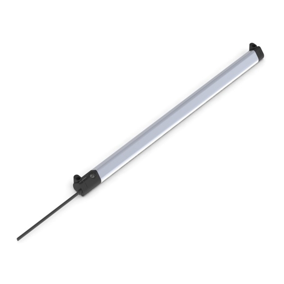
BMP 01- _P _ _ _ _ _A- _ _ _ _ - _ _ -P _ _ /P _ _ -S4/P _ _ -S75 Magnetfeld-Positionsmesssystem Produktbeschreibung BMP 01-…-S4 Kerbe Kerbe Positionsgeber Aktive Fläche Messbereich BMP 01-…-S75 Erfassungsbereich Gehäuselänge Bohrabstand BMP 01-…-Kabel Befestigungsstelle Befestigungsstelle Markierung des Messbereichs Taster Nicht im Lieferumfang enthalten Bild 4-1: Magnetfeld-Positionsmesssystem BMP 01-…, Aufbau und Funktion Aufbau Funktion Elektrischer Anschluss: Der elektrische Anschluss ist... -
Seite 11: Produktbeschreibung
Seite 16 und Kapitel 8.5.2 auf Seite 25). 5 Hz Tab. 4-1: LED-Anzeige Hinweis, Tipp Ein dauerhaftes, asynchrones Blinken aller LEDs zeigt einen schwerwiegenden Fehler an. Das BMP muss möglicherweise ausgetauscht werden. Typenschild Bestellcode Seriennummer Bild 4-3: Typenschild (Ausschnitt, Beispiel) www.balluff.com deutsch... -
Seite 12: Einbau Und Anschluss
BMP 01- _P _ _ _ _ _A- _ _ _ _ - _ _ -P _ _ /P _ _ -S4/P _ _ -S75 Magnetfeld-Positionsmesssystem Einbau und Anschluss Es sind drei Varianten für den Einbau vorgesehen: – Befestigung über eine C- oder T-Nut an einem Pneu- matikzylinder (siehe Kapitel 5.1). – Befestigung über Schlauchschellen und Rundzylinder- halter an einem Rundzylinder (siehe Kapitel 5.2). -
Seite 13: Montage An Einem Pneumatikzylinder Mit T- Oder C-Nut
Nutensteine in der Nut fixiert (Seitenansicht; T-Nut links, C-Nut rechts im Bild) 2. Nutensteine mit gerader Seite parallel zur Nut ausrich- ⇒ Nutensteine werden um 90° gedreht. ten. ⇒ Das BMP ist fixiert. Bild 5-3: Nutensteine ausrichten (T-Nut links, C-Nut rechts im Bild) www.balluff.com deutsch... -
Seite 14: Montage An Einem Rundzylinder
BMP 01- _P _ _ _ _ _A- _ _ _ _ - _ _ -P _ _ /P _ _ -S4/P _ _ -S75 Magnetfeld-Positionsmesssystem Einbau und Anschluss (Fortsetzung) Montage an einem Rundzylinder Die Montage an einem Rundzylinder erfolgt mit Schlauch- schellen und Rundzylinderhaltern (siehe Zubehör auf Seite 35). 1. Rundzylinderhalter auf das BMP klemmen. Dabei auf die Orientierung der Halter achten (siehe Bild 5-8). -
Seite 15: Montage Mit Freiem Positionsgeber
Fläche befestigen. Bild 5-12: Abstände und Toleranzen, gezeigt am Beispiel eines Rundmagnet-Positionsgebers Ø10×10 mm mit einer Remanenz BR ~360 mT (radial polarisiert) Bohrabstand Bohrabstand = Messbereich + 2 mm (Toleranz des Loch- bildes = ±0,05 mm) Beispiel: Messbereich 128 mm Bohrabstand = 130 mm ±0,05 mm www.balluff.com deutsch... -
Seite 16: Elektrischer Anschluss
BMP 01- _P _ _ _ _ _A- _ _ _ _ - _ _ -P _ _ /P _ _ -S4/P _ _ -S75 Magnetfeld-Positionsmesssystem Einbau und Anschluss (Fortsetzung) Montagebeispiel mit Positionsgeber BAM TG-MP-028 Elektrischer Anschluss BMP 01-…-P_ _-S75 BMP 01-…-P_ _-S4 M 8-4 (Class A) M 12-4 (Class A) Bild 5-19: Pinbelegung Steckverbinder (Draufsicht auf Stiftseite) Pin Adernfarbe Signal Braun +24 V (Betriebsspannung UB+) -
Seite 17: Inbetriebnahme
Werte prüfen. Hinweise zum Betrieb – Funktion des BMP und aller damit verbundenen Kom- ponenten regelmäßig überprüfen. – Bei Funktionsstörungen das BMP außer Betrieb neh- men. – Anlage gegen unbefugte Benutzung sichern. – Befestigung prüfen und ggf. nachziehen. www.balluff.com deutsch... -
Seite 18: Analoge Schnittstelle. Schaltausgang Und Magnettypauswahl
BMP 01- _P _ _ _ _ _A- _ _ _ _ - _ _ -P _ _ /P _ _ -S4/P _ _ -S75 Magnetfeld-Positionsmesssystem Analoge Schnittstelle. Schaltausgang und Magnettypauswahl Schaltausgang Bei aktiver IO-Link Kommunikation ist der Analogausgang deaktiviert. Schaltsignal (Schließer / Öffner) Das Verhalten kann per Taster oder via IO-Link verändert Der minimale einstellbare Messereich beträgt werden. - Seite 19 8 × Rot aus Bild 7-7: Übersicht Einstellmodus (Einstellungen über den Taster, Analogausgang) Wird der Sensor im Kompatibilitätsmodus (siehe Kommunikationsparameter auf Seite 19) betrieben, so entfällt Magnettyp einstellen. Rücksetzen auf Werkseinstellung wird in diesem Fall bei 7x drücken ausgeführt. www.balluff.com deutsch...
- Seite 20 BMP 01- _P _ _ _ _ _A- _ _ _ _ - _ _ -P _ _ /P _ _ -S4/P _ _ -S75 Magnetfeld-Positionsmesssystem Analoge Schnittstelle, Schaltausgang und Magnettypauswahl (Fortsetzung) BMP 01-ZPZ _ _ _ _A-_ _ _ _-_ _-P_ _/P_ _-S4/P_ _-S75 Legende Normalbetrieb Taster kurz Taster für 2 s drücken gedrückt halten Einstellfehler...
-
Seite 21: Io-Link-Schnittstelle
Der Master kann bei Bedarf die Zykluszeit erhöhen, deshalb hängt die tatsächlich verwen- dete Zykluszeit (MasterCycleTime) vom Master Beim Hochfahren befindet sich der Sensor im SIO-Modus. Nach einem Neustart (Power Cycle) oder Fallback-Kommando kehrt der Sensor in den SIO-Modus zurück. www.balluff.com deutsch... - Seite 22 BMP 01- _P _ _ _ _ _A- _ _ _ _ - _ _ -P _ _ /P _ _ -S4/P _ _ -S75 Magnetfeld-Positionsmesssystem IO-Link Schnittstelle (Fortsetzung) Prozessdaten (PD) Im Fehlerfall werden die Daten mithilfe des PD Invalid Bit nur dann als ungültig gekennzeichnet, wenn das Gerät Die Varianten des BMP geben über die IO-Link-Schnitt- überhaupt keine gültigen Daten liefern kann.
-
Seite 23: Identifikationsdaten
Parametermanager übernommen werden. Über Subindex 0 erfolgt der Zugriff auf das gesamte Objekt. Product Type Code Der Balluff Typenschlüssel ist fest im Gerät hinterlegt. Product Order Code Der Balluff Bestellcode ist fest im Gerät hinterlegt. www.balluff.com deutsch... -
Seite 24: Systembefehle
BMP 01- _P _ _ _ _ _A- _ _ _ _ - _ _ -P _ _ /P _ _ -S4/P _ _ -S75 Magnetfeld-Positionsmesssystem IO-Link Schnittstelle (Fortsetzung) Systembefehle Beim BMP sind verschiedene Befehle implementiert, die über den Parameter System Command auf Index 2, Subindex 0 erreicht werden können. Wird ein Systembefehl an das BMP übermittelt, löst der Befehl die gewünschte Aktion aus, sofern dies im aktuellen Applikationszustand zulässig ist. - Seite 25 Device Access Locks (siehe Kapitel 8.5.11) 2 Byte Read/Write 0x000D (13) 0, 1, 2, 3, 4 ProfileCharacteristic (siehe Kapitel 8.5.12) 8 Byte Read Only 0x000E (14) 0, 1, 2, 3 PD Input Descriptor (siehe Kapitel 8.5.13) 9 Byte Read Only Tab. 8-6: Parameterdaten IO-Link-Schnittstelle www.balluff.com deutsch...
-
Seite 26: Messwertkonfiguration (Mdc)
BMP 01- _P _ _ _ _ _A- _ _ _ _ - _ _ -P _ _ /P _ _ -S4/P _ _ -S75 Magnetfeld-Positionsmesssystem IO-Link Schnittstelle (Fortsetzung) 8.5.1 Messwertkonfiguration (MDC) Ein Ändern der Messwertkonfiguration beein- flusst das Schaltverhalten. Die Schaltsignalkon- Das BMP gibt die gemessene Position über den Messwert figuration (siehe Kapitel 8.5.3) muss gegebe- (Measurement Value) an den IO-Link Master weiter. -
Seite 27: Frontend Settings (Magnettyp Und Sensordynamik)
Ermöglicht es, zwischen einem axial.- bzw. einem radial- magnetisierten Magneten als Positionsgeber zu wechseln. Averaging of sensor measurement signal (Sensordynamik) Bei langsamen Bewegungen bzw. im statischen Zustand des Positionsgebers, wird der Ausgabewert gefiltert (default). Sofern eine höhere Dynamik gewünscht wird, kann die Filterung deaktiviert werden. www.balluff.com deutsch... - Seite 28 BMP 01- _P _ _ _ _ _A- _ _ _ _ - _ _ -P _ _ /P _ _ -S4/P _ _ -S75 Magnetfeld-Positionsmesssystem IO-Link Schnittstelle (Fortsetzung) 8.5.3 Schaltsignalkonfiguration (SSC) Vor Beginn der Schaltsignalkonfiguration muss die Messwertkonfiguration (siehe Kapitel 8.5.1) abgeschlossen sein! Das BMP hat 4 Schaltsignale integriert. Jedes Schaltsignal wird von zwei Parametern beschrieben (Parameter und Configuration).
-
Seite 29: Ausgangskonfiguration
1 = Meldungen unterdrückt Configuration 2 = Meldungen und Warnungen unterdrückt 0x00F8 (248) 3 = Alle Ereignisse unterdrückt PD Invalid Suppression 1 Byte Read/Write 0x00 (0) = PD Invalid aktiv 0xFF (255) = PD Invalid unterdrückt Tab. 8-12: Diagnoseunterdrückung www.balluff.com deutsch... -
Seite 30: Temperaturerfassung
BMP 01- _P _ _ _ _ _A- _ _ _ _ - _ _ -P _ _ /P _ _ -S4/P _ _ -S75 Magnetfeld-Positionsmesssystem IO-Link Schnittstelle (Fortsetzung) 8.5.6 Temperaturerfassung 8.5.8 Betriebsstundenzähler Die Betriebsstunden werden innerhalb des BMP erfasst Folgende Temperaturwerte werden vom BMP als vorzei- und im Stundenintervall permanent gespeichert chenbehaftete 16-Bit-Werte mit der Einheit °C ausgegeben (Index 0x0057 (87)). - Seite 31 – Subindex 1 (DeviceProfileID): 0×000B (Measuring Sensor, high resolution according to Smart Sensor Profile Edition 2) – Subindex 2 (DeviceProfileID): 0×4000 (Identification and Diagnosis according to Common Profile) – Subindex 3 (FunctionClassID): 0×8001 (SSC Function Class) – Subindex 4 (FunctionClassID): 0×8004 (Teach Channel) www.balluff.com deutsch...
-
Seite 32: Diagnosedaten
BMP 01- _P _ _ _ _ _A- _ _ _ _ - _ _ -P _ _ /P _ _ -S4/P _ _ -S75 Magnetfeld-Positionsmesssystem IO-Link Schnittstelle (Fortsetzung) Diagnosedaten Das BMP meldet Diagnosedaten (Events) an das steu- ernde System (siehe Tab. 8-16) oder das steuernde Sys- tem kann den Status über die Diagnose-Parameter ausle- sen. -
Seite 33: Geräte-Fehlermeldungen
Index not available 0×8012 Subindex not available 0x8023 Access denied 0×8030 Value out of range 0×8033 Parameter length overrun 0×8034 Parameter length underrun 0×8036 Function temporarily unavailable 0x8040 Invalid parameter set 0x8082 Application not ready Tab. 8-18: Fehlermeldungen IO-Link-Spezifikation www.balluff.com deutsch... -
Seite 34: Reparatur Und Entsorgung
BMP 01- _P _ _ _ _ _A- _ _ _ _ - _ _ -P _ _ /P _ _ -S4/P _ _ -S75 Magnetfeld-Positionsmesssystem Reparatur und Entsorgung Reparatur Reparaturen am Produkt dürfen nur von Balluff durchge- führt werden. Sollte das Produkt defekt sein, nehmen Sie Kontakt mit unserem Service-Center auf. -
Seite 35: Technische Daten
…P_ _-S75 M8×1-Stecker, 4-polig …P_ _-S4 M12×1-Stecker, 4-polig Schockbelastung Halbsinus, 30 g, 11 ms …P_ _ offenes Kabelende nach EN 60068-2-27 Vibration 55 Hz, 1-mm-Amplitude, Verbindungsart Kabel mit/ohne Stecker nach EN 60068-2-6 3 × 30 min Anzahl Leiter Schutzart nach IEC 60529 IP67 Verpolungsschutz Kurzschlussfestigkeit Kabelmantelmaterial www.balluff.com deutsch... -
Seite 36: Ausgang / Schnittstelle
Die Produkte müssen über eine SELV/Limited Energy- oder Class-2-Ver- sorgung betrieben werden. 10.8 Zulassungen und Kennzeichnungen Mit dem CE-Zeichen bestätigen wir, dass unsere Produkte den Anforderungen der aktuellen EU-Richtlinie entsprechen. Nähere Informationen zu Richtlinien, Zulas- sungen und Normen finden Sie unter www.balluff.com auf der Produktseite. deutsch... -
Seite 37: Zubehör
10/20 mm 5 mm 18…29 mm BAM00N4 Bestellcode: BAM0427 – 2 Nutensteine C-Nut 30 mm 5 mm 28…39 mm BAM00N5 – 2 Schrauben 40 mm 5 mm 38…49 mm BAM00N6 50 mm 5 mm 48…59 mm BAM00N7 Tab. 11-1: Schlauchschellen für entsprechende Kolbendurchmesser Bild 11-4: Montageset C-Nut www.balluff.com deutsch... -
Seite 38: Typenschlüssel
BMP 01- _P _ _ _ _ _A- _ _ _ _ - _ _ -P _ _ /P _ _ -S4/P _ _ -S75 Magnetfeld-Positionsmesssystem Typenschlüssel BMP 01-EP1PP21A-0128-00-P00,5-S75 Schnittstelle, analog: Z = kein Analogausgang E = Spannungsausgang 0…10 V (Werkseinstellung) oder Stromausgang 4…20 mA F = Spannungsausgang 0…10 V oder Stromausgang 4…20 mA (Werkseinstellung) Konfigurationsschnittstelle: P = IO-Link Schnittstelle (Parametrierung) - Seite 39 BMP 01- _P _ _ _ _ _A- _ _ _ _ - _ _-P_ _ BMP 01- _P _ _ _ _ _A- _ _ _ _ - _ _-P_ _ -S4 BMP 01- _P _ _ _ _ _A- _ _ _ _ - _ _-P_ _ -S75 User’s guide english...
- Seite 40 www.balluff.com...
- Seite 41 Installation at a round cylinder Installation with free position magnet Electrical Connection Cable routing Startup Starting up the system Operating notes Analog interface. Switching output and magnet type selection Voltage output 0…10 V Current output 4…20 mA Switching output Settings using the buttons www.balluff.com english...
- Seite 42 BMP 01- _P _ _ _ _ _A- _ _ _ _ - _ _ -P _ _ /P _ _ -S4/P _ _ -S75 Magnetic field positioning system IO-Link interface Communication parameters Process data (PD) Identification data System commands Parameter data 8.5.1 Measurement Data Configuration (MDC) 8.5.2 Front-end settings (magnet type and sensor dynamics) 8.5.3 Switching Signal Configuration (SSC) 8.5.4 Output configuration 8.5.5 Diagnostics suppression...
-
Seite 43: About This Guide
CAUTION indicates a hazard which can lead to slight or moderate injuries. Additional information about this product can be found at www.balluff.com on the product page, e.g. in the DANGER following documents: The general warning symbol in conjunction with the –... -
Seite 44: Safety
Balluff accessories. Otherwise, there is deemed to be unintended use. Unintended use is not permitted and will result in the loss of warranty and liability claims against the manufacturer. -
Seite 45: Scope Of Delivery, Transport And Storage
Transport ► Transport product to location of use in original packaging. Storage conditions ► Store product in original packaging. ► Observe ambient conditions (see Ambient conditions on page 33). www.balluff.com english... -
Seite 46: Product Description
BMP 01- _P _ _ _ _ _A- _ _ _ _ - _ _ -P _ _ /P _ _ -S4/P _ _ -S75 Magnetic field positioning system Product description BMP 01-…-S4 Notch Notch Position magnet Active surface Measurement range BMP 01-…-S75 Detection range Housing length Drilling distance BMP 01-… cable Attachment point Attachment point Marking of measurement range Button Not included in scope of delivery... -
Seite 47: Analog And Switching Output
Section 8.5.2 on page 25). Tab. 4-1: LED display Note, tip Continuous, asynchronous flashing of all LEDs indicates a serious error. The BMP may have to be replaced. Part label Order code Type Serial number Bild 4-3: Part label (section, example) www.balluff.com english... -
Seite 48: Installation And Connection
BMP 01- _P _ _ _ _ _A- _ _ _ _ - _ _ -P _ _ /P _ _ -S4/P _ _ -S75 Magnetic field positioning system Installation and connection There are three options for the installation: – Mounting via a C- or T-slot at a pneumatic cylinder (see Section 5.1). –... -
Seite 49: Installation At A Pneumatic Cylinder With T- Or C-Slot
2. Align sliding blocks with straight edge parallel to the ⇒ Sliding blocks are turned 90°. slot. ⇒ The BMP is fixed. Bild 5-3: Align sliding blocks (T-slot left, C-slot right in the image) www.balluff.com english... -
Seite 50: Installation At A Round Cylinder
BMP 01- _P _ _ _ _ _A- _ _ _ _ - _ _ -P _ _ /P _ _ -S4/P _ _ -S75 Magnetic field positioning system Installation and connection (continued) Installation at a round cylinder The installation at a round cylinder is realized with hose clamps and round cylinder holders (see Accessories on page 35). -
Seite 51: Installation With Free Position Magnet
Distances and tolerances, shown using the example of a round magnet-position magnet Ø10×10 mm with a remanence BR ~360 mT (radially polarized) Drilling distance Drilling distance = Measurement range + 2 mm (tolerance of hole pattern = ±0.05 mm) Example: Measurement range 128 mm Drilling distance = 130 mm ±0.05 mm www.balluff.com english... -
Seite 52: Electrical Connection
BMP 01- _P _ _ _ _ _A- _ _ _ _ - _ _ -P _ _ /P _ _ -S4/P _ _ -S75 Magnetic field positioning system Installation and connection (continued) Mounting example with position magnet Electrical Connection BAM TG-MP-028 BMP 01-…-P_ _-S75 BMP 01-…-P_ _-S4 M 8-4 (Class A) M 12-4 (Class A) Bild 5-19: Pin assignments for connector (pin side view) Pin Wire color Signal... -
Seite 53: Startup
Operating notes – Regularly check function of the BMP and all associated components. – Take the BMP out of operation whenever there is a malfunction. – Secure the system against unauthorized use. – Check fasteners and retighten if needed. www.balluff.com english... -
Seite 54: Analog Interface. Switching Output And Magnet Type Selection
BMP 01- _P _ _ _ _ _A- _ _ _ _ - _ _ -P _ _ /P _ _ -S4/P _ _ -S75 Magnetic field positioning system Analog interface. Switching output and magnet type selection Switching output The analog output is deactivated with active IO-Link communication. Switching signal (NO contact/NC contact) The behavior can be changed using buttons or via IO-Link. - Seite 55 Overview of setting mode (settings using the buttons, analog output) If the sensor is operated in Compatibility Mode (see Communication parameters on page 19), then Set magnet type is omitted. In this case, to reset to factory setting the button must be pressed seven times. www.balluff.com english...
- Seite 56 BMP 01- _P _ _ _ _ _A- _ _ _ _ - _ _ -P _ _ /P _ _ -S4/P _ _ -S75 Magnetic field positioning system Analog interface, switching output and magnet type selection (cont.) BMP 01-ZPZ _ _ _ _A-_ _ _ _-_ _-P_ _/P_ _-S4/P_ _-S75 Legend Normal operation Press button Hold down button...
-
Seite 57: Io-Link Interface
If needed the master can increase the cycle time, which is why the actual used cycle time (MasterCycleTime) depends on the master. During start-up the sensor is in SIO mode. After a restart (Power Cycle) or fallback command the sensor returns to SIO mode. www.balluff.com english... -
Seite 58: Process Data (Pd)
BMP 01- _P _ _ _ _ _A- _ _ _ _ - _ _ -P _ _ /P _ _ -S4/P _ _ -S75 Magnetic field positioning system IO-Link interface (continued) Process data (PD) In the event of an error, the data are only marked as invalid using the PD Invalid Bit if the device cannot deliver any The variants of the BMP use the IO-Link interface to output valid data. -
Seite 59: Identification Data
The entire object is accessed via subindex 0. Product Type Code The Balluff type code is stored permanently in the device. Product Order Code The Balluff order code is stored permanently in the device. www.balluff.com... -
Seite 60: System Commands
BMP 01- _P _ _ _ _ _A- _ _ _ _ - _ _ -P _ _ /P _ _ -S4/P _ _ -S75 Magnetic field positioning system IO-Link interface (continued) System commands Different commands have been implemented in the BMP which can be reached via the parameter System Command on Index 2, Subindex 0. If a system command is transferred to the BMP, the command triggers the desired action if permitted in the current application state. - Seite 61 Device Access Locks (see Section 8.5.11) 2 bytes Read/Write 0x000D (13) 0, 1, 2, 3, 4 ProfileCharacteristic (see Section 8.5.12) 8 bytes Read Only 0x000E (14) 0, 1, 2, 3 PD Input Descriptor (see Section 8.5.13) 9 bytes Read Only Tab. 8-6: Parameter data of IO-Link interface www.balluff.com english...
-
Seite 62: Measurement Data Configuration (Mdc)
BMP 01- _P _ _ _ _ _A- _ _ _ _ - _ _ -P _ _ /P _ _ -S4/P _ _ -S75 Magnetic field positioning system IO-Link interface (continued) 8.5.1 Measurement Data Configuration (MDC) Changing the measurement value configuration affects the switching behavior. The switching The BMP passes the measured position to the IO-Link signal configuration (see Section 8.5.3) must master using the measurement value. -
Seite 63: Front-End Settings (Magnet Type And Sensor Dynamics)
Averaging of sensor measurement signal (sensor dynamics) The output value is filtered for slow movements or if the position magnet is in a static state (default). The filtering can be deactivated if a higher dynamic is desired. www.balluff.com english... - Seite 64 BMP 01- _P _ _ _ _ _A- _ _ _ _ - _ _ -P _ _ /P _ _ -S4/P _ _ -S75 Magnetic field positioning system IO-Link interface (continued) 8.5.3 Switching Signal Configuration (SSC) The measurement value configuration must be finished before starting the switching signal (see Section 8.5.1)! The BMP has 4 switching signals integrated into it.
-
Seite 65: Output Configuration
1 = Messages suppressed Configuration 2 = Messages and warnings suppressed 0x00F8 (248) 3 = All events suppressed PD Invalid Suppression 1 byte Read/Write 0x00 (0) = PD Invalid active 0xFF (255) = PD Invalid suppressed Tab. 8-12: Diagnostics suppression www.balluff.com english... -
Seite 66: Temperature Sensing
BMP 01- _P _ _ _ _ _A- _ _ _ _ - _ _ -P _ _ /P _ _ -S4/P _ _ -S75 Magnetic field positioning system IO-Link interface (continued) 8.5.6 Temperature sensing 8.5.8 Operating hours counter The following temperature values are output by the BMP The operating hours are acquired within the BMP and as signed 16-bit values in units of °C (Index 0x0052 (82)): permanently stored in hour intervals (Index 0x0057 (87)). -
Seite 67: 8.5.10 Data Storage
– Subindex 1 (DeviceProfileID): 0×000B (Measuring Sensor, high resolution according to Smart Sensor Profile Edition 2) – Subindex 2 (DeviceProfileID): 0×4000 (Identification and Diagnosis according to Common Profile) – Subindex 3 (FunctionClassID): 0×8001 (SSC Function Class) – Subindex 4 (FunctionClassID): 0×8004 (Teach Channel) www.balluff.com english... -
Seite 68: Diagnostic Data
BMP 01- _P _ _ _ _ _A- _ _ _ _ - _ _ -P _ _ /P _ _ -S4/P _ _ -S75 Magnetic field positioning system IO-Link interface (continued) Diagnostic data The BMP reports diagnostic data (events) to the controlling system (see Tab. 8-16) or the controlling system can read out the status using the diagnostics parameters. -
Seite 69: Device Error Messages
0×8012 Subindex not available 0x8023 Access denied 0×8030 Value out of range 0×8033 Parameter length overrun 0×8034 Parameter length underrun 0×8036 Function temporarily unavailable 0x8040 Invalid parameter set 0x8082 Application not ready Tab. 8-18: IO-Link specification error messages www.balluff.com english... -
Seite 70: Repair And Disposal
BMP 01- _P _ _ _ _ _A- _ _ _ _ - _ _ -P _ _ /P _ _ -S4/P _ _ -S75 Magnetic field positioning system Repair and disposal Repair Repairs to the product may only be performed by Balluff. If the product is defective, contact our Service Center. Disposal ► Observe the national regulations for disposal. -
Seite 71: Technical Data
Half sine, 30 g, 11 ms …P_ _ Open cable end per EN 60068-2-27 Vibration 55 Hz, 1 mm amplitude, Connection type Cable with/without per EN 60068-2-6 3 × 30 min connector Protection class per IP67 Number of conductors IEC 60529 Reverse polarity protection Short-circuit resistance Cable coating material www.balluff.com english... -
Seite 72: Output / Interface
The products must be operated via a SELV/Limited Energy or Class 2 supply. 10.8 Approvals and markings The CE Mark verifies that our products meet the requirements of the current EU Directive. Additional information on directives, approvals and standards can be found at www.balluff.com on the product page. english... -
Seite 73: Accessories
Order code: BAM0427 30 mm 5 mm 28…39 mm BAM00N5 – 2 sliding blocks C-slot 40 mm 5 mm 38…49 mm BAM00N6 – 2 screws 50 mm 5 mm 48…59 mm BAM00N7 Tab. 11-1: Hose clamps for corresponding piston diameter Bild 11-4: Mounting kit C-slot www.balluff.com english... -
Seite 74: Type Code
BMP 01- _P _ _ _ _ _A- _ _ _ _ - _ _ -P _ _ /P _ _ -S4/P _ _ -S75 Magnetic field positioning system Type code BMP 01-EP1PP21A-0128-00-P00,5-S75 Interface, analog: Z = no analog output E = Voltage output 0…10 V (factory setting) or current output 4…20 mA F = Voltage output 0…10 V or current output 4…20 mA (factory setting) Configuration interface:... - Seite 75 BMP 01- _P _ _ _ _ _A- _ _ _ _ - _ _-P_ _ BMP 01- _P _ _ _ _ _A- _ _ _ _ - _ _-P_ _ -S4 BMP 01- _P _ _ _ _ _A- _ _ _ _ - _ _-P_ _ -S75 Notice d’utilisation français...
- Seite 76 www.balluff.com...
- Seite 77 Pose des câbles Mise en service Mise en service du système Conseils d’utilisation Interface analogique. Sortie de commutation et sélection du type d’aimant Sortie tension 0…10 V Sortie courant 4…20 mA Sortie de commutation Réglages par le biais de la touche www.balluff.com français...
- Seite 78 BMP 01- _P _ _ _ _ _A- _ _ _ _ - _ _ -P _ _ /P _ _ -S4/P _ _ -S75 Système de mesure de position magnétique Interface IO-Link Paramètres de communication Données de processus (DP) Données d’identification Ordres système Données de paramètre 8.5.1 Configuration de la valeur mesurée (MDC) 8.5.2 Frontend settings (type d’aimant et dynamique de capteur) 8.5.3 Configuration du signal de commutation (SSC) 8.5.4 Configuration de sortie...
-
Seite 79: A Propos De Cette Notice
Autres documents de référence Le symbole « Attention » accompagné du mot DANGER Vous trouverez des informations complémentaires caractérise un danger pouvant entraîner directement la concernant ce produit sous www.balluff.com, sur la mort ou des blessures graves. page produit, p. ex. dans les documents suivants : –... -
Seite 80: Sécurité
Balluff appropriés. Dans le cas contraire, il s’agit d’une utilisation non conforme. Celle-ci n’est pas autorisée et entraîne la perte des droits de garantie et de responsabilité... -
Seite 81: Fourniture, Transport Et Stockage
être commandés séparément. Transport ► Transporter le produit dans son emballage d’origine jusqu’au lieu d’utilisation. Conditions de stockage ► Stocker le produit dans son emballage d’origine. ► Respecter les conditions ambiantes (voir Conditions ambiantes, page 33). www.balluff.com français... -
Seite 82: Description Du Produit
BMP 01- _P _ _ _ _ _A- _ _ _ _ - _ _ -P _ _ /P _ _ -S4/P _ _ -S75 Système de mesure de position magnétique Description du produit BMP 01-…-S4 Entaille Entaille Capteur de Face sensible position Plage de mesure BMP 01-…-S75 Zone de détection Longueur de boîtier Écartement des trous de perçage Câble BMP 01-…... -
Seite 83: Sortie Analogique Et Sortie De Commutation
Tab. 4-1 : Affichage à LED Conseils et astuces Un clignotement permanent et asynchrone de toutes les LED indique une erreur grave. Le BMP doit éventuellement être remplacé. Plaque signalétique Symbolisation commerciale Type Numéro de série Fig. 4-3 : Plaque signalétique (extrait, exemple) www.balluff.com français... -
Seite 84: Montage Et Raccordement
BMP 01- _P _ _ _ _ _A- _ _ _ _ - _ _ -P _ _ /P _ _ -S4/P _ _ -S75 Système de mesure de position magnétique Montage et raccordement Trois variantes sont prévues pour le montage : – Fixation par le biais d’une rainure en C ou en T sur un vérin pneumatique (voir chapitre 5.1). -
Seite 85: Montage Sur Un Vérin Pneumatique Avec Rainure En T Ou En C
2. Aligner les écrous coulissants avec le côté droit parallèle à la rainure. ⇒ Les coulisseaux sont tournés de 90°. ⇒ Le BMP est fixé. Fig. 5-3 : Aligner les coulisseaux (rainure en T à gauche, rainure en C à droite dans la figure) www.balluff.com français... -
Seite 86: Montage Sur Un Vérin Cylindrique
BMP 01- _P _ _ _ _ _A- _ _ _ _ - _ _ -P _ _ /P _ _ -S4/P _ _ -S75 Système de mesure de position magnétique Montage et raccordement (suite) Montage sur un vérin cylindrique Le montage sur un vérin cylindrique s’effectue au moyen de colliers de serrage et de supports pour vérin cylindrique (voir les accessoires, page 35). -
Seite 87: Montage Avec Capteur De Position Libre
BR ~360 mT (polarisation radiale) Écartement des trous de perçage Écartement des trous de perçage = plage de mesure + 2 mm (tolérance de la configuration de perçage = ±0,05 mm) Exemple : Plage de mesure 128 mm Écartement des trous de perçage = 130 mm ±0,05 mm www.balluff.com français... -
Seite 88: Raccordement Électrique
BMP 01- _P _ _ _ _ _A- _ _ _ _ - _ _ -P _ _ /P _ _ -S4/P _ _ -S75 Système de mesure de position magnétique Montage et raccordement (suite) Exemple de montage avec capteur de position Raccordement électrique BAM TG-MP-028 BMP 01-…-P_ _-S75 BMP 01-…-P_ _-S4 M 8-4 (Class A) M 12-4 (Class A) Fig. -
Seite 89: Mise En Service Du Système
– Contrôler régulièrement le fonctionnement du BMP et de tous les composants associés. – En cas de dysfonctionnement, mettre le BMP hors service. – Protéger l’installation de toute utilisation non autorisée. – Contrôler la fixation, resserrer si nécessaire. www.balluff.com français... -
Seite 90: Interface Analogique. Sortie De Commutation Et Sélection Du Type D'aimant
BMP 01- _P _ _ _ _ _A- _ _ _ _ - _ _ -P _ _ /P _ _ -S4/P _ _ -S75 Système de mesure de position magnétique Interface analogique. Sortie de commutation et sélection du type d’aimant Sortie de commutation Lorsque la communication IO-Link est active, la sortie analogique est désactivée. Signal de commutation (contact à... - Seite 91 Aperçu du mode de réglage (réglages via la touche, sortie analogique) Si le capteur est utilisé en mode compatibilité (voir Paramètres de communication, page 19), le réglage du type d’aimant est inutile. Dans ce cas, la réinitialisation aux réglages usine s’effectue en appuyant 7 fois sur la touche. www.balluff.com français...
-
Seite 92: Fonctionnement Normal
BMP 01- _P _ _ _ _ _A- _ _ _ _ - _ _ -P _ _ /P _ _ -S4/P _ _ -S75 Système de mesure de position magnétique Interface analogique, sortie de commutation et sélection du type d’aimant (suite) BMP 01-ZPZ _ _ _ _A-_ _ _ _-_ _-P_ _/P_ _-S4/P_ _-S75 Légende Fonctionnement normal Appui bref sur... -
Seite 93: Interface Io-Link
; par conséquent, le temps de cycle (MasterCycleTime) effectivement utilisé dépend du module Master. Au démarrage, le capteur est en mode SIO. Après un redémarrage (Power Cycle) ou une commande Fallback, le capteur repasse en mode SIO. www.balluff.com français... -
Seite 94: Données De Processus (Dp)
BMP 01- _P _ _ _ _ _A- _ _ _ _ - _ _ -P _ _ /P _ _ -S4/P _ _ -S75 Système de mesure de position magnétique Interface IO-Link (suite) Données de processus (DP) En cas d’erreur, les données ne sont marquées comme non valables à l’aide du PD Invalid Bit que si l’appareil ne Les variantes du BMP délivrent de façon cyclique via peut pas du tout fournir de données valables. -
Seite 95: Données D'identification
à l’application et reprise dans le gestionnaire de paramètres. L’accès à l’objet entier a lieu via le subindex 0. Product Type Code Le code de type Balluff est enregistré de manière fixe dans l’appareil. Product Order Code La symbolisation commerciale Balluff est enregistrée de manière fixe dans l’appareil. - Seite 96 BMP 01- _P _ _ _ _ _A- _ _ _ _ - _ _ -P _ _ /P _ _ -S4/P _ _ -S75 Système de mesure de position magnétique Interface IO-Link (suite) Ordres système Pour le BMP, différentes commandes sont implémentées et sont accessibles via le paramètre System Command sur Index 2, Subindex 0.
- Seite 97 2 octets Read/Write 0x000D (13) 0, 1, 2, 3, 4 ProfileCharacteristic (voir chapitre 8.5.12) 8 octets Read Only 0x000E (14) 0, 1, 2, 3 PD Input Descriptor (voir chapitre 8.5.13) 9 octets Read Only Tab. 8-6 : Données de paramètre pour interface IO-Link www.balluff.com français...
-
Seite 98: Configuration De La Valeur Mesurée (Mdc)
BMP 01- _P _ _ _ _ _A- _ _ _ _ - _ _ -P _ _ /P _ _ -S4/P _ _ -S75 Système de mesure de position magnétique Interface IO-Link (suite) 8.5.1 Configuration de la valeur mesurée (MDC) Une modification de la configuration de la valeur mesurée influence le comportement de Le BMP transmet la position mesurée via la valeur mesurée commutation. -
Seite 99: Frontend Settings (Type D'aimant Et Dynamique De Capteur)
En cas de mouvements lents ou lorsque le capteur de position est à l’état statique, la valeur de sortie est filtrée (valeur par défaut). Dans la mesure où une dynamique supérieure est souhaitée, le filtrage peut être désactivé. www.balluff.com français... - Seite 100 BMP 01- _P _ _ _ _ _A- _ _ _ _ - _ _ -P _ _ /P _ _ -S4/P _ _ -S75 Système de mesure de position magnétique Interface IO-Link (suite) 8.5.3 Configuration du signal de commutation (SSC) Avant de commencer la configuration du signal de commutation, la configuration de la valeur mesurée (voir chapitre 8.5.1) doit être terminée ! Le BMP possède 4 signaux de commutation intégrés.
-
Seite 101: Configuration De Sortie
0x00F8 (248) 2 = Messages et avertissements inhibés 3 = Tous les événements inhibés PD Invalid Suppression 1 octet Read/Write 0x00 (0) = PD Invalid actif 0xFF (255) = PD Invalid inhibé Tab. 8-12 : Inhibition du diagnostic www.balluff.com français... -
Seite 102: Mesure De La Température
BMP 01- _P _ _ _ _ _A- _ _ _ _ - _ _ -P _ _ /P _ _ -S4/P _ _ -S75 Système de mesure de position magnétique Interface IO-Link (suite) 8.5.6 Mesure de la température 8.5.8 Compteurs d’heures de service Les heures de service sont saisies au sein du BMP et Les valeurs de température suivantes sont émises par le enregistrées en permanence toutes les heures BMP en tant que valeurs 16 bits signées, avec l’unité... -
Seite 103: Stockage Des Données (Data Storage)
Subindex 1 (DeviceProfileID) : 0×000B (Measuring Sensor, high resolution according to Smart Sensor Profile Edition 2) – Subindex 2 (DeviceProfileID): 0×4000 (Identification and Diagnosis according to Common Profile) – Subindex 3 (FunctionClassID): 0×8001 (SSC Function Class) – Subindex 4 (FunctionClassID): 0×8004 (Teach Channel) www.balluff.com français... -
Seite 104: Données De Diagnostic
BMP 01- _P _ _ _ _ _A- _ _ _ _ - _ _ -P _ _ /P _ _ -S4/P _ _ -S75 Système de mesure de position magnétique Interface IO-Link (suite) Données de diagnostic Le BMP signale les données de diagnostic (événements) au système pilote (voir Tab. 8-16) ou le système pilote peut lire l’état via les paramètres de diagnostic. -
Seite 105: Messages D'erreur De L'appareil
0x8023 Access denied 0×8030 Value out of range 0×8033 Parameter length overrun 0×8034 Parameter length underrun 0×8036 Function temporarily unavailable 0x8040 Invalid parameter set 0x8082 Application not ready Tab. 8-18 : Messages d’erreur relatifs à la spécification IO-Link www.balluff.com français... -
Seite 106: Réparation Et Élimination
Les réparations du produit ne peuvent être effectuées que par Balluff. Si le produit est défectueux, veuillez contacter notre centre de service. Élimination ► Pour l’élimination des déchets, se conformer aux dispositions nationales. Vous trouverez des informations complémentaires sous www.balluff.com, sur la page produit. français... -
Seite 107: Caractéristiques Techniques
EN 60068-2-6 3 × 30 min 4 pôles Classe de protection selon IP67 Extrémité de câble CEI 60529 ouverte Type de connexion Câble avec/sans connecteur Nombre de conducteurs Protection contre l’inversion de polarité Résistance aux courts-circuits Matériau de la gaine de câble www.balluff.com français... -
Seite 108: Sortie / Interface
Homologations et certifications Avec le symbole CE, nous certifions que nos produits répondent aux exigences de la directive UE actuelle. Vous trouverez plus d’informations sur les directives, les homologations et les normes sur la page produit du site www.balluff.com. français... -
Seite 109: Accessoires
– 2 vis 30 mm 5 mm 28…39 mm BAM00N5 40 mm 5 mm 38…49 mm BAM00N6 50 mm 5 mm 48…59 mm BAM00N7 Tab. 11-1 : Colliers de serrage pour diamètres de piston correspondants Fig. 11-4 : Kit de montage pour rainure en C www.balluff.com français... -
Seite 110: Code De Type
BMP 01- _P _ _ _ _ _A- _ _ _ _ - _ _ -P _ _ /P _ _ -S4/P _ _ -S75 Système de mesure de position magnétique Code de type BMP 01-EP1PP21A-0128-00-P00,5-S75 Interface, analogique : Z = Pas de sortie analogique E = Sortie tension 0…10 V (réglage usine) ou sortie courant 4…20 mA F = Sortie tension 0…10 V ou sortie courant 4…20 mA (réglage usine) - Seite 111 BMP 01- _P _ _ _ _ _A- _ _ _ _ - _ _-P_ _ BMP 01- _P _ _ _ _ _A- _ _ _ _ - _ _-P_ _ -S4 BMP 01- _P _ _ _ _ _A- _ _ _ _ - _ _-P_ _ -S75 Manuale d’uso italiano...
- Seite 112 www.balluff.com...
- Seite 113 Posa del cavo Messa in funzione Messa in funzione del sistema Avvertenze per il funzionamento Interfaccia analogica. Uscita di commutazione e selezione del tipo di magnete 16 Uscita tensione 0…10 V Uscita corrente 4…20 mA Uscita di commutazione Impostazioni tramite il tasto www.balluff.com italiano...
- Seite 114 BMP 01- _P _ _ _ _ _A- _ _ _ _ - _ _ -P _ _ /P _ _ -S4/P _ _ -S75 Sensore di posizionamento lineare a campo magnetico Interfaccia IO-Link Parametri di comunicazione Dati di processo (PD) Dati identificazione Comandi di sistema Dati parametrici 8.5.1 Configurazione valore misurato (MDC) 8.5.2 Frontend settings (tipo di magnete e dinamica del sensore) 8.5.3 Configurazione segnale di commutazione (SSC) 8.5.4 Configurazione uscita...
-
Seite 115: Informazioni Sulle Presenti Istruzioni
Documenti di riferimento che può provocare lesioni di media/lieve entità. Ulteriori informazioni sul presente prodotto sono disponibili PERICOLO all’indirizzo www.balluff.com, pagina Prodotti, ad es. nei Il simbolo di pericolo generico in abbinamento alla parola seguenti documenti: di segnalazione PERICOLO contraddistingue un pericolo –... -
Seite 116: Uso Conforme
Balluff. In caso contrario, si tratta di uso improprio. Questo non è consentito e determina la decadenza di qualsiasi garanzia o responsabilità... -
Seite 117: Fornitura, Trasporto E Magazzinaggio
Trasporto ► Trasportare il prodotto nella confezione originale fino al luogo di utilizzo. Condizioni di magazzinaggio ► Conservare il prodotto nella confezione originale. ► Attenersi alle condizioni ambientali (vedere Condizioni ambientali a pag. 33). www.balluff.com italiano... -
Seite 118: Descrizione Del Prodotto
BMP 01- _P _ _ _ _ _A- _ _ _ _ - _ _ -P _ _ /P _ _ -S4/P _ _ -S75 Sensore di posizionamento lineare a campo magnetico Descrizione del prodotto BMP 01-…-S4 Tacca Tacca Trasduttore di Superficie attiva posizione Campo di misura BMP 01-…-S75 Campo di rilevamento Lunghezza corpo Interasse fori Cavo BMP 01-…... -
Seite 119: Uscita Analogica E Uscita Di Commutazione
Avvertenza, suggerimento Un lampeggio continuo ed asincrono di tutti i LED lampeggio indica un errore grave. Potrebbe essere necessario sostituire il BMP. Targhetta di identificazione Codice d’ordine Tipo Numero di serie Fig. 4-3: Targhetta di identificazione (particolare, esempio) www.balluff.com italiano... -
Seite 120: Montaggio E Collegamento
BMP 01- _P _ _ _ _ _A- _ _ _ _ - _ _ -P _ _ /P _ _ -S4/P _ _ -S75 Sensore di posizionamento lineare a campo magnetico Montaggio e collegamento Sono previste tre varianti di montaggio: – Fissaggio tramite una scanalatura a C o a T su un cilindro pneumatico (vedere capitolo 5.1). -
Seite 121: Montaggio Su Un Cilindro Pneumatico Con Scanalatura A T O A C
⇒ I blocchetti di fissaggio filettati vanno ruotati di 90°. ⇒ Il BMP è fissato. Fig. 5-3: Allineamento dei blocchetti di fissaggio filettati (scanalatura a T a sinistra, scanalatura a C a destra in figura) www.balluff.com italiano... -
Seite 122: Montaggio Su Un Cilindro Circolare
BMP 01- _P _ _ _ _ _A- _ _ _ _ - _ _ -P _ _ /P _ _ -S4/P _ _ -S75 Sensore di posizionamento lineare a campo magnetico Montaggio e collegamento (seguito) Montaggio su un cilindro circolare Il montaggio su un cilindro circolare va effettuato con fascette serratubi e supporti per cilindri circolari (vedere Accessori a pag. 35). -
Seite 123: Montaggio Con Trasduttore Di Posizione Libero
Ø 10×10 mm con rimanenza BR ~360 mT (a polarizzazione radiale) Interasse fori Interasse fori = campo di misura + 2 mm (tolleranza dello schema di foratura = ± 0,05 mm) Esempio: Campo di misura 128 mm Interasse fori = 130 mm ± 0,05 mm www.balluff.com italiano... -
Seite 124: Collegamento Elettrico
BMP 01- _P _ _ _ _ _A- _ _ _ _ - _ _ -P _ _ /P _ _ -S4/P _ _ -S75 Sensore di posizionamento lineare a campo magnetico Montaggio e collegamento (seguito) Esempio di montaggio con trasduttore di posizione Collegamento elettrico BAM TG-MP-028 BMP 01-…-P_ _-S75 BMP 01-…-P_ _-S4 M 8-4 (Class A) M 12-4 (Class A) Fig. -
Seite 125: Messa In Funzione
Avvertenze per il funzionamento – Controllare periodicamente il funzionamento del BMP e di tutti i componenti ad esso collegati. – In caso di malfunzionamenti, disattivare il BMP. – Proteggere l’impianto dagli utilizzi non autorizzati. – Controllare il fissaggio e, all’occorrenza, riserrare. www.balluff.com italiano... -
Seite 126: Interfaccia Analogica. Uscita Di Commutazione E Selezione Del Tipo Di Magnete
BMP 01- _P _ _ _ _ _A- _ _ _ _ - _ _ -P _ _ /P _ _ -S4/P _ _ -S75 Sensore di posizionamento lineare a campo magnetico Interfaccia analogica. Uscita di commutazione e selezione del tipo di magnete Uscita di commutazione Se la comunicazione IO-Link è attiva, l’uscita analogica è... -
Seite 127: Modalità Impostazione
Panoramica della modalità Impostazione (impostazioni tramite il tasto, uscita analogica) Se il sensore viene utilizzato in modalità Compatibilità (vedere Parametri di comunicazione a pag. 19), non occorrerà l’Impostazione del tipo di magnete. In tale caso, il reset all’impostazione predefinita andrà eseguito premendo 7 volte. www.balluff.com italiano... - Seite 128 BMP 01- _P _ _ _ _ _A- _ _ _ _ - _ _ -P _ _ /P _ _ -S4/P _ _ -S75 Sensore di posizionamento lineare a campo magnetico Interfaccia analogica, uscita di commutazione e selezione del tipo di magnete (seguito) BMP 01-ZPZ _ _ _ _A-_ _ _ _-_ _-P_ _/P_ _-S4/P_ _-S75 Legenda Esercizio normale Premere...
-
Seite 129: Interfaccia Io-Link
(MasterCycleTime) dipende dal master. In fase di avvio, il sensore si trova in modalità SIO. Dopo un riavvio (Power Cycle) o un comando Fallback, il sensore tornerà in modalità SIO. www.balluff.com italiano... -
Seite 130: Dati Di Processo (Pd)
BMP 01- _P _ _ _ _ _A- _ _ _ _ - _ _ -P _ _ /P _ _ -S4/P _ _ -S75 Sensore di posizionamento lineare a campo magnetico Interfaccia IO-Link (seguito) Dati di processo (PD) In caso di errore, mediante il PD Invalid Bit, i dati verranno contrassegnati come non validi soltanto se l’apparecchio Tramite l’interfaccia IO-Link, le varianti del BMP emettono non potrà... -
Seite 131: Dati Identificazione
Gestione parametri. Per accedere all’intero oggetto si utilizza il subindice 0. Product Type Code Il codice di identificazione Balluff è memorizzato in modo permanente nell’apparecchio. Product Order Code Il codice d’ordine Balluff è memorizzato in modo permanente nell’apparecchio. -
Seite 132: Comandi Di Sistema
BMP 01- _P _ _ _ _ _A- _ _ _ _ - _ _ -P _ _ /P _ _ -S4/P _ _ -S75 Sensore di posizionamento lineare a campo magnetico Interfaccia IO-Link (seguito) Comandi di sistema Nel BMP sono implementati diversi comandi, accessibili mediante il parametro System Command su Index 2, Subindex 0. -
Seite 133: Dati Parametrici
2 byte Read/Write capitolo 8.5.11) 0x000D (13) 0, 1, 2, 3, 4 ProfileCharacteristic (vedere capitolo 8.5.12) 8 byte Read Only 0x000E (14) 0, 1, 2, 3 PD Input Descriptor (vedere capitolo 8.5.13) 9 byte Read Only Tab. 8-6: Dati parametrici interfaccia IO-Link www.balluff.com italiano... - Seite 134 BMP 01- _P _ _ _ _ _A- _ _ _ _ - _ _ -P _ _ /P _ _ -S4/P _ _ -S75 Sensore di posizionamento lineare a campo magnetico Interfaccia IO-Link (seguito) 8.5.1 Configurazione valore misurato (MDC) Una variazione della configurazione valore misurato influisce il comportamento di Il BMP inoltra la posizione misurata, tramite il valore commutazione.
-
Seite 135: Frontend Settings (Tipo Di Magnete E Dinamica Del Sensore)
Averaging of sensor measurement signal (dinamica del sensore) In caso di movimenti lenti, oppure se il trasduttore di posizione si trova in condizioni statiche, il valore di emissione viene filtrato (default). Se si desidera una dinamica maggiore, il filtro si potrà disattivare. www.balluff.com italiano... - Seite 136 BMP 01- _P _ _ _ _ _A- _ _ _ _ - _ _ -P _ _ /P _ _ -S4/P _ _ -S75 Sensore di posizionamento lineare a campo magnetico Interfaccia IO-Link (seguito) 8.5.3 Configurazione segnale di commutazione (SSC) Prima d’iniziare la configurazione segnale di commutazione, dovrà essere completata la configurazione valore misurato (vedere capitolo 8.5.1)! Il BMP ha 4 segnali di commutazione integrati.
-
Seite 137: Configurazione Uscita
Configuration 2 = Messaggi ed avvisi soppressi 0x00F8 (248) 3 = Tutti gli eventi soppressi PD Invalid Suppression 1 byte Read/Write 0x00 (0) = PD Invalid attivo 0xFF (255) = PD Invalid soppresso Tab. 8-12: Soppressione della diagnosi www.balluff.com italiano... -
Seite 138: Rilevamento Temperatura
BMP 01- _P _ _ _ _ _A- _ _ _ _ - _ _ -P _ _ /P _ _ -S4/P _ _ -S75 Sensore di posizionamento lineare a campo magnetico Interfaccia IO-Link (seguito) 8.5.6 Rilevamento temperatura 8.5.8 Contaore d’esercizio Le ore d’esercizio vengono rilevate all’interno del BMP e I seguenti valori di temperatura vengono emessi dal BMP sono memorizzate in modo permanente nell’intervallo delle come valori a 16 bit, con o senza segno, con l’unità... -
Seite 139: Archiviazione Dati (Data Storage)
– Subindex 1 (DeviceProfileID): 0×000B (Measuring Sensor, high resolution according to Smart Sensor Profile Edition 2) – Subindice 2 (DeviceProfileID): 0×4000 (Identification and Diagnosis according to Common Profile) – Subindice 3 (FunctionClassID): 0×8001 (SSC Function Class) – Subindice 4 (FunctionClassID): 0×8004 (Teach Channel) www.balluff.com italiano... -
Seite 140: Dati Di Diagnosi
BMP 01- _P _ _ _ _ _A- _ _ _ _ - _ _ -P _ _ /P _ _ -S4/P _ _ -S75 Sensore di posizionamento lineare a campo magnetico Interfaccia IO-Link (seguito) Dati di diagnosi Il BMP segnala dati di diagnosi (Events) al sistema di comando (vedere Tab. 8-16), oppure il sistema di comando può... -
Seite 141: Messaggi Di Errore Apparecchio
Subindex not available 0x8023 Access denied 0×8030 Value out of Range 0×8033 Parameter Length overrun 0×8034 Parameter Length underrun 0×8036 Function temporarily unavailable 0x8040 Invalid parameter set 0x8082 Application not ready Tab. 8-18: Messaggi di errore specifica IO-Link www.balluff.com italiano... -
Seite 142: Riparazione E Smaltimento
Sensore di posizionamento lineare a campo magnetico Riparazione e smaltimento Riparazione Gli interventi di riparazione sul prodotto andranno effettuati esclusivamente da Balluff. Qualora il prodotto dovesse presentare difetti, contattare il nostro Service Center. Smaltimento ► Seguire le disposizioni nazionali per lo smaltimento. -
Seite 143: Dati Tecnici
Connettore M12×1, a Grado di protezione secondo IP67 4 poli IEC 60529 Estremità aperta del cavo Tipo di collegamento Cavo con/senza connettore Numero di conduttori Protezione contro l’inversione di Sì polarità Resistenza al cortocircuito Sì Materiale guaina di protezione cavo www.balluff.com italiano... -
Seite 144: Uscita/Interfaccia
I prodotti andranno utilizzati con un’alimentazione SELV/Limited Energy, oppure Class 2. 10.8 Autorizzazioni e contrassegni Il marchio CE è la conferma che i nostri prodotti sono conformi ai requisiti dell’attuale Direttiva UE. Ulteriori informazioni su direttive, omologazioni e norme sono disponibili all’indirizzo www.balluff.com, pagina Prodotti. italiano... -
Seite 145: Accessori
2 blocchetti di fissaggio filettati con scanalatura a C – 2 viti 30 mm 5 mm 28…39 mm BAM00N5 40 mm 5 mm 38…49 mm BAM00N6 50 mm 5 mm 48…59 mm BAM00N7 Tab. 11-1: Fascette serratubi per relativi diametri pistone Fig. 11-4: Kit di montaggio scanalatura a C www.balluff.com italiano... -
Seite 146: Legenda Codici Di Identificazione
BMP 01- _P _ _ _ _ _A- _ _ _ _ - _ _ -P _ _ /P _ _ -S4/P _ _ -S75 Sensore di posizionamento lineare a campo magnetico Legenda codici di identificazione BMP 01-EP1PP21A-0128-00-P00,5-S75 Interfaccia, analogica: Z = Nessuna uscita analogica E = Uscita tensione 0…10 V (impostazione predefinita) oppure uscita corrente 4…20 mA F = Uscita tensione 0…10 V oppure uscita corrente 4…20 mA (impostazione predefinita) - Seite 147 BMP 01- _P _ _ _ _ _A- _ _ _ _ - _ _-P_ _ BMP 01- _P _ _ _ _ _A- _ _ _ _ - _ _-P_ _ -S4 BMP 01- _P _ _ _ _ _A- _ _ _ _ - _ _-P_ _ -S75 Manual de instrucciones español...
- Seite 148 www.balluff.com...
- Seite 149 Puesta en servicio Puesta en servicio del sistema Indicaciones sobre el servicio Interfaz analógica. Salida de conmutación y selección del tipo de imán Salida de tensión 0…10 V Salida de corriente 4…20 mA Salida de conmutación Ajustes mediante el detector www.balluff.com español...
- Seite 150 BMP 01- _P _ _ _ _ _A- _ _ _ _ - _ _ -P _ _ /P _ _ -S4/P _ _ -S75 Sistema de medición de posición del campo magnético Interfaz IO-Link Parámetros de comunicación Datos de proceso (PD) Datos de identificación Comandos del sistema Datos de parámetros 8.5.1 Configuración de valores de medición (MDC) 8.5.2 Frontend settings (tipo de imán y dinámica de sensor) 8.5.3 Configuración de señal de conmutación (SSC) 8.5.4 Configuración de salida...
-
Seite 151: Acerca De Este Manual
PRECAUCIÓN, indica un peligro que puede provocar lesiones leves o medias. Encontrará información detallada sobre este producto en www.balluff.com en la página del producto, por ejemplo, PELIGRO en los siguientes documentos: El símbolo de advertencia general, en combinación con –... -
Seite 152: Uso Debido
Balluff adecuados. De lo contrario, se trata de un uso indebido. Este no se permite y conduce a la pérdida de la garantía y... -
Seite 153: Volumen De Suministro, Transporte Y Almacenamiento
Transporte ► Transportar el producto en el embalaje original al lugar de uso. Condiciones de almacenamiento ► Almacenar el producto en el embalaje original. ► Tener en cuenta las condiciones ambientales (véase Condiciones ambientales en la página 33). www.balluff.com español... -
Seite 154: Descripción De Producto
BMP 01- _P _ _ _ _ _A- _ _ _ _ - _ _ -P _ _ /P _ _ -S4/P _ _ -S75 Sistema de medición de posición del campo magnético Descripción de producto BMP 01-…-S4 Muesca Muesca Sensor de Superficie activa posición Zona medible BMP 01-…-S75 Zona de captación Longitud de la carcasa Distancia de taladrado Cable BMP 01-…... -
Seite 155: Salida Analógica Y Salida De Conmutación
Indicación, consejo Un parpadeo asincrónico permanente de todos los LED indica un error grave. Es posible que haya que sustituir el BMP. Placa de características Código de pedido Tipo Número de serie Fig. 4-3: Placa de características (extracto, ejemplo) www.balluff.com español... -
Seite 156: Montaje Y Conexión
BMP 01- _P _ _ _ _ _A- _ _ _ _ - _ _ -P _ _ /P _ _ -S4/P _ _ -S75 Sistema de medición de posición del campo magnético Montaje y conexión Se han previsto tres variantes para el montaje: – Fijación a través de una ranura en C o en T en un cilindro neumático (véase el capítulo 5.1). -
Seite 157: Montaje En Un Cilindro Neumático Con Ranura En T O En C
2. Alinear las correderas con lado recto en paralelo con ⇒ Las correderas se giran 90°. respecto a la ranura. ⇒ El BMP está fijado. Fig. 5-3: Alinear las correderas (ranura en T a la izquierda, ranura en C a la derecha en la imagen) www.balluff.com español... -
Seite 158: Montaje En Un Cilindro Circular
BMP 01- _P _ _ _ _ _A- _ _ _ _ - _ _ -P _ _ /P _ _ -S4/P _ _ -S75 Sistema de medición de posición del campo magnético Montaje y conexión (continuación) Montaje en un cilindro circular El montaje en un cilindro circular se realiza con abrazaderas de manguera y soportes de cilindro circular (véase Accesorios en la página 35). -
Seite 159: Montaje Con Sensor De Posición Libre
BR ~360 mT (polarizado radialmente) sobre una superficie. Distancia de taladrado Distancia de taladrado = zona medible + 2 mm (tolerancia de la plantilla de orificios = ±0,05 mm) Ejemplo: Zona medible 128 mm Distancia de taladrado = 130 mm ±0,05 mm www.balluff.com español... -
Seite 160: Conexión Eléctrica
BMP 01- _P _ _ _ _ _A- _ _ _ _ - _ _ -P _ _ /P _ _ -S4/P _ _ -S75 Sistema de medición de posición del campo magnético Montaje y conexión (continuación) Ejemplo de montaje con sensor de posición Conexión eléctrica BAM TG-MP-028 BMP 01-…-P_ _-S75 BMP 01-…-P_ _-S4 M 8-4 (Class A) M 12-4 (Class A) Fig. -
Seite 161: Puesta En Servicio
BMP y de todos los componentes relacionados. – Si se producen fallos de funcionamiento, ponga fuera de servicio el BMP. – Asegure la instalación contra cualquier uso no autorizado. – Comprobar la fijación y reapretar en caso necesario. www.balluff.com español... -
Seite 162: Interfaz Analógica. Salida De Conmutación Y Selección Del Tipo De Imán
BMP 01- _P _ _ _ _ _A- _ _ _ _ - _ _ -P _ _ /P _ _ -S4/P _ _ -S75 Sistema de medición de posición del campo magnético Interfaz analógica. Salida de conmutación y selección del tipo de imán Salida de conmutación Si la comunicación de IO-Link está activa, la salida analógica está... - Seite 163 Si el sensor funciona en el modo de compatibilidad (véase Parámetros de comunicación en la página 19), se suprime Ajustar el tipo de imán. En este caso, el restablecimiento de los ajustes de fábrica se realiza con 7 pulsaciones. www.balluff.com español...
- Seite 164 BMP 01- _P _ _ _ _ _A- _ _ _ _ - _ _ -P _ _ /P _ _ -S4/P _ _ -S75 Sistema de medición de posición del campo magnético Interfaz analógica, salida de conmutación y selección del tipo de imán (continuación) BMP 01-ZPZ _ _ _ _A-_ _ _ _-_ _-P_ _/P_ _-S4/P_ _-S75 Leyenda Servicio normal Pulsar el...
-
Seite 165: Interfaz Io-Link
(MasterCycleTime) depende del maestro. Al arrancar, el sensor está en modo SIO. Tras un reinicio (Power Cycle) o un comando de retroceso, el sensor vuelve al modo SIO. www.balluff.com español... -
Seite 166: Datos De Proceso (Pd)
BMP 01- _P _ _ _ _ _A- _ _ _ _ - _ _ -P _ _ /P _ _ -S4/P _ _ -S75 Sistema de medición de posición del campo magnético Interfaz de IO-Link (continuación) Datos de proceso (PD) En caso de un fallo solo se identifican los datos técnicos como no válidos con ayuda del PD Invalid Bit si el Las variantes del BMP emiten a través de la interfaz dispositivo no es capaz de suministrar datos válidos. -
Seite 167: Datos De Identificación
Mediante el subíndice 0 se accede al objeto completo. Product Type Code El código de modelo de Balluff está guardado firmemente en el dispositivo. Product Order Code El código de pedido de Balluff está guardado firmemente en el dispositivo. -
Seite 168: Comandos Del Sistema
BMP 01- _P _ _ _ _ _A- _ _ _ _ - _ _ -P _ _ /P _ _ -S4/P _ _ -S75 Sistema de medición de posición del campo magnético Interfaz de IO-Link (continuación) Comandos del sistema En el BMP se han implementado diferentes comandos a los que puede accederse a través del parámetros System Command en índice 2, subíndice 0. -
Seite 169: Datos De Parámetros
0, 1, 2, 3, 4 ProfileCharacteristic (véase el capítulo 8.5.12) 8 bytes Read Only 0x000E (14) 0, 1, 2, 3 PD Input Descriptor (véase el capítulo 8.5.13) 9 bytes Read Only Tab. 8-6: Datos de parámetros de la interfaz IO-Link www.balluff.com español... -
Seite 170: Configuración De Valores De Medición (Mdc)
BMP 01- _P _ _ _ _ _A- _ _ _ _ - _ _ -P _ _ /P _ _ -S4/P _ _ -S75 Sistema de medición de posición del campo magnético Interfaz de IO-Link (continuación) 8.5.1 Configuración de valores de medición (MDC) Cualquier cambio de la configuración de valores de medición repercute sobre el comportamiento El BMP transmite la posición medida a través del valor de de conmutación. -
Seite 171: Frontend Settings (Tipo De Imán Y Dinámica De Sensor)
Averaging of sensor measurement signal (dinámica de sensor) En caso de movimientos lentos o en estado estático del sensor de posición, se filtra el valor de emisión (por defecto). Si se desea una dinámica mayor, es posible desactivar el filtrado. www.balluff.com español... - Seite 172 BMP 01- _P _ _ _ _ _A- _ _ _ _ - _ _ -P _ _ /P _ _ -S4/P _ _ -S75 Sistema de medición de posición del campo magnético Interfaz de IO-Link (continuación) 8.5.3 Configuración de señal de conmutación (SSC) ¡La configuración de valores de medición (véase el capítulo 8.5.1) debe haber finalizado antes de comenzar la configuración de señal de conmutación! El BMP tiene 4 señales de conmutación integradas.
-
Seite 173: Configuración De Salida
1 = mensajes suprimidos 0x00F8 (248) 2 = mensajes y avisos suprimidos 3 = todas las incidencias suprimidas PD Invalid Suppression 1 byte Read/Write 0x00 (0) = PD Invalid activo 0xFF (255) = PD Invalid suprimido Tab. 8-12: Supresión de diagnóstico www.balluff.com español... -
Seite 174: Captación De Temperatura
BMP 01- _P _ _ _ _ _A- _ _ _ _ - _ _ -P _ _ /P _ _ -S4/P _ _ -S75 Sistema de medición de posición del campo magnético Interfaz de IO-Link (continuación) 8.5.6 Captación de temperatura 8.5.8 Contador de horas de servicio Los siguientes valores de temperatura son emitidos por el Las horas de servicio se registran en el interior del BMP y BMP como valores de 16 bitscon signo con la unidad °C se guardan permanentemente en un intervalo de una hora... -
Seite 175: Mantenimiento De Datos (Data Storage)
– Subíndice 1 (DeviceProfileID): 0×000B (Measuring Sensor, high resolution according to Smart Sensor Profile Edition 2) – Subíndice 2 (DeviceProfileID): 0×4000 (Identification and Diagnosis according to Common Profile) – Subíndice 3 (FunctionClassID): 0×8001 (SSC Function Class) – Subíndice 4 (FunctionClassID): 0×8004 (Teach Channel) www.balluff.com español... -
Seite 176: Datos De Diagnóstico
BMP 01- _P _ _ _ _ _A- _ _ _ _ - _ _ -P _ _ /P _ _ -S4/P _ _ -S75 Sistema de medición de posición del campo magnético Interfaz de IO-Link (continuación) Datos de diagnóstico El BMP transfiere los datos de diagnóstico (evento) al sistema de control (véase Tab. 8-16) o el sistema de control puede leer el estado a través de los parámetros de diagnóstico. -
Seite 177: Mensajes De Error De Aparato
Subindex not available 0x8023 Access denied 0×8030 Value out of range 0×8033 Parameter length overrun 0×8034 Parameter length underrun 0×8036 Function temporarily unavailable 0x8040 Invalid parameter set 0x8082 Application not ready Tab. 8-18: Mensajes de error de la especificación IO-Link www.balluff.com español... -
Seite 178: Reparación Y Eliminación De Desechos
BMP 01- _P _ _ _ _ _A- _ _ _ _ - _ _ -P _ _ /P _ _ -S4/P _ _ -S75 Sistema de medición de posición del campo magnético Reparación y eliminación de desechos Reparación Solo Balluff puede llevar a cabo reparaciones en el producto. Si el producto estuviera defectuoso, póngase en contacto con nuestro centro de servicio técnico. -
Seite 179: Datos Técnicos
Grado de protección según IP67 M12×1, 4 polos IEC 60529 Extremo de cable abierto Tipo de conexión Cable con/sin conector macho Número de conductores Protección contra polarización Sí inversa Resistencia a cortocircuitos Sí Material de la cubierta del cable PUR www.balluff.com español... -
Seite 180: Salida/Interfaz
Energía Limitada o Clase 2. 10.8 Homologaciones e identificaciones Con el marcado CE confirmamos que nuestros productos cumplen con los requerimientos de la directiva UE actual. Encontrará información detallada sobre directivas, homologaciones y normas en www.balluff.com en la página del producto. español... -
Seite 181: Accesorios
18…29 mm BAM00N4 – 2 tornillos 30 mm 5 mm 28…39 mm BAM00N5 40 mm 5 mm 38…49 mm BAM00N6 50 mm 5 mm 48…59 mm BAM00N7 Tab. 11-1: Abrazaderas de manguera para los correspondientes diámetros de pistón Fig. 11-4: Set de montaje para ranura en C www.balluff.com español... -
Seite 182: Código De Modelo
BMP 01- _P _ _ _ _ _A- _ _ _ _ - _ _ -P _ _ /P _ _ -S4/P _ _ -S75 Sistema de medición de posición del campo magnético Código de modelo BMP 01-EP1PP21A-0128-00-P00,5-S75 Interfaz, analógica: Ninguna salida analógica Salida de tensión 0…10 V (Ajuste de fábrica) o salida de corriente 4…20 mA Salida de tensión 0…10 V o salida de corriente 4…20 mA (ajuste de fábrica) Interfaz de configuración:... - Seite 183 BMP 01- _P _ _ _ _ _A- _ _ _ _ - _ _-P_ _ BMP 01- _P _ _ _ _ _A- _ _ _ _ - _ _-P_ _ -S4 BMP 01- _P _ _ _ _ _A- _ _ _ _ - _ _-P_ _ -S75 Manual de Instruções português...
- Seite 184 www.balluff.com...
- Seite 185 Instalação dos cabos Inicialização Ativação do sistema Avisos sobre o funcionamento Interface analógica. Saída de comutação e seleção do tipo de ímã Saída de tensão 0…10 V Saída de corrente 4…20 mA Saída de comutação Ajustes por meio do botão www.balluff.com português...
- Seite 186 BMP 01- _P _ _ _ _ _A- _ _ _ _ - _ _ -P _ _ /P _ _ -S4/P _ _ -S75 Sistema de medição de posição do campo magnético Interface IO-Link Parâmetros de comunicação Dados de processo (PD) Dados de identificação Comandos do sistema Dados dos parâmetros 8.5.1 Configuração do valor medido (MDC) 8.5.2 Frontend settings (tipo de ímã...
-
Seite 187: Sobre Este Manual
Mais informações sobre este produto em PERIGO www.balluff.com na página do produto, nos seguintes O símbolo de alerta geral em conexão com a palavra de documentos, por exemplo: sinalização PERIGO assinala um perigo que conduz –... -
Seite 188: Utilização Prevista
Balluff adequados. Caso contrário, irá se configurar uma utilização indevida. Esta não é permitida e irá resultar na perda dos direitos de garantia e de responsabilidade perante o fabricante. -
Seite 189: Escopo De Fornecimento, Transporte E Armazenamento
Transporte ► Transportar o produto em sua embalagem original até o local de uso. Condições de armazenamento ► Armazenar o produto na embalagem original. ► Observar as condições ambientais (consultar Condições ambientais na página 33). www.balluff.com português... -
Seite 190: Descrição Do Produto
BMP 01- _P _ _ _ _ _A- _ _ _ _ - _ _ -P _ _ /P _ _ -S4/P _ _ -S75 Sistema de medição de posição do campo magnético Descrição do produto BMP 01-…-S4 Entalhe Entalhe Codificador de Área ativa posição Faixa de medição BMP 01-…-S75 Faixa de detecção Comprimento da carcaça Distância de perfuração BMP 01-...-cabo Ponto de fixação... -
Seite 191: Saída Analógica E De Comutação
Tab. 4-1: Indicação de LED Aviso, dica Uma sinalização contínua e assíncrona de todos os LEDs indica um erro grave. O BMP pode precisar ser substituído. Etiquetas Código de pedido Tipo Número de série Fig. 4-3: Etiquetas (recorte, exemplo) www.balluff.com português... -
Seite 192: Montagem E Acoplamento
BMP 01- _P _ _ _ _ _A- _ _ _ _ - _ _ -P _ _ /P _ _ -S4/P _ _ -S75 Sistema de medição de posição do campo magnético Montagem e acoplamento Há três variantes para instalação: – Fixação através de uma ranhura em C ou em T em um cilindro pneumático (consulte o capítulo 5.1). -
Seite 193: Montagem Em Um Cilindro Pneumático Com Ranhura Em T Ou Em C
2. Alinhar as porcas de slot com o lado reto paralelo à ⇒ As porcas de slot são giradas em 90°. ranhura. ⇒ O BMP está fixado. Fig. 5-3: Alinhar as porcas de slot (ranhura em T à esquerda, ranhura em C à direita na imagem) www.balluff.com português... -
Seite 194: Montagem Em Um Cilindro Redondo
BMP 01- _P _ _ _ _ _A- _ _ _ _ - _ _ -P _ _ /P _ _ -S4/P _ _ -S75 Sistema de medição de posição do campo magnético Montagem e acoplamento (continuação) Montagem em um cilindro redondo A montagem em um cilindro redondo é feita com braçadeiras para mangueiras e suportes de cilindro redondo (consulte os acessórios na página 35). -
Seite 195: Montagem Com Codificador De Posição Livre
ímã redondo Ø10×10 mm com uma remanência BR ~360 mT (radialmente polarizado) Distância de perfuração Distância de perfuração = faixa de medição + 2 mm (tolerância do padrão do furo = ±0,05 mm) Exemplo: Faixa de medição 128 mm Distância de perfuração = 130 mm ±0,05 mm www.balluff.com português... -
Seite 196: Conexão Elétrica
BMP 01- _P _ _ _ _ _A- _ _ _ _ - _ _ -P _ _ /P _ _ -S4/P _ _ -S75 Sistema de medição de posição do campo magnético Montagem e acoplamento (continuação) Exemplo de montagem com codificador de posição Conexão elétrica BAM TG-MP-028 BMP 01-…-P_ _-S75 BMP 01-…-P_ _-S4 M 8-4 (Class A) M 12-4 (Class A) Fig. -
Seite 197: Ativação Do Sistema
Verificar regularmente o funcionamento do BMP e todos os componentes associados. – Em caso de falhas de funcionamento, desativar o BMP. – Proteger a instalação contra uma utilização não autorizada. – Verificar o aperto e, se necessário, apertar mais. www.balluff.com português... -
Seite 198: Interface Analógica. Saída De Comutação E Seleção Do Tipo De Ímã
BMP 01- _P _ _ _ _ _A- _ _ _ _ - _ _ -P _ _ /P _ _ -S4/P _ _ -S75 Sistema de medição de posição do campo magnético Interface analógica. Saída de comutação e seleção do tipo de ímã Saída de comutação Com a comunicação IO-Link ativa, a saída analógica está... - Seite 199 Se o sensor for operado em modo de compatibilidade (consulte Parâmetros de comunicação na página 19), não há necessidade de ajustar o tipo de ímã. Neste caso, a reinicialização para o ajuste de fábrica é feita pressionando 7 vezes. www.balluff.com português...
- Seite 200 BMP 01- _P _ _ _ _ _A- _ _ _ _ - _ _ -P _ _ /P _ _ -S4/P _ _ -S75 Sistema de medição de posição do campo magnético Interface analógica, saída de comutação e seleção do tipo de ímã (continuação) BMP 01-ZPZ _ _ _ _A-_ _ _ _-_ _-P_ _/P_ _-S4/P_ _-S75 Legendas Operação normal Pressionar o...
- Seite 201 O master pode aumentar o tempo de ciclo se necessário, portanto o tempo de ciclo efetivamente utilizado (MasterCycleTime) depende do master. Na partida, o sensor está no modo SIO. Após uma reinicialização (Power Cycle) ou comando de retorno, o sensor retorna ao modo SIO. www.balluff.com português...
-
Seite 202: Interface Io-Link
BMP 01- _P _ _ _ _ _A- _ _ _ _ - _ _ -P _ _ /P _ _ -S4/P _ _ -S75 Sistema de medição de posição do campo magnético IO-Link (continuação) Dados de processo (PD) No caso de um erro, os dados só são marcados como inválidos com a ajuda do PD Invalid Bit se o dispositivo As variantes do BMP emitem ciclicamente um valor não puder fornecer nenhum dado válido. -
Seite 203: Dados De Identificação
O objeto inteiro é acessado por meio do subíndice 0. Product Type Code O código do tipo Balluff está armazenado permanentemente no dispositivo. Product Order Code O código do pedido Balluff está armazenado permanentemente no dispositivo. -
Seite 204: Comandos Do Sistema
BMP 01- _P _ _ _ _ _A- _ _ _ _ - _ _ -P _ _ /P _ _ -S4/P _ _ -S75 Sistema de medição de posição do campo magnético IO-Link (continuação) Comandos do sistema Vários comandos estão implementados no BMP, que podem ser alcançados por meio do parâmetro System Command no Índice 2, Subíndice 0. - Seite 205 0x000D (13) 0, 1, 2, 3, 4 ProfileCharacteristic (consulte o 8 bytes Read Only capítulo 8.5.12) 0x000E (14) 0, 1, 2, 3 PD Input Descriptor (consulte o 9 bytes Read Only capítulo 8.5.13) Tab. 8-6: Dados dos parâmetros da interface IO-Link www.balluff.com português...
-
Seite 206: Configuração Do Valor Medido (Mdc)
BMP 01- _P _ _ _ _ _A- _ _ _ _ - _ _ -P _ _ /P _ _ -S4/P _ _ -S75 Sistema de medição de posição do campo magnético IO-Link (continuação) 8.5.1 Configuração do valor medido (MDC) A alteração da configuração do valor medido influencia o comportamento de comutação. A O BMP encaminha a posição medida para o master configuração do sinal de comutação (consulte o IO-Link por meio do valor medido (Measurement Value). -
Seite 207: Frontend Settings (Tipo De Ímã E Dinâmica Do Sensor)
Averaging of sensor measurement signal (dinâmica do sensor) No caso de movimentos lentos ou no estado estático do codificador de posição, o valor de saída é filtrado (default). Se uma faixa dinâmica mais alta for desejada, a filtragem poderá ser desativada. www.balluff.com português... - Seite 208 BMP 01- _P _ _ _ _ _A- _ _ _ _ - _ _ -P _ _ /P _ _ -S4/P _ _ -S75 Sistema de medição de posição do campo magnético IO-Link (continuação) 8.5.3 Configuração do sinal de comutação (SSC) Antes de iniciar a configuração do sinal de comutação, a configuração do valor medido (consulte o capítulo 8.5.1) deve ser completada! O BMP tem 4 sinais de comutação integrados.
-
Seite 209: Configuração De Saída
Configuration 2 = mensagens e advertências suprimidas 0x00F8 (248) 3 = todos os eventos suprimidos PD Invalid Suppression 1 byte Read/Write 0x00 (0) = PD Invalid ativo 0xFF (255) = PD Invalid suprimido Tab. 8-12: Supressão de diagnóstico www.balluff.com português... -
Seite 210: Detecção De Temperatura
BMP 01- _P _ _ _ _ _A- _ _ _ _ - _ _ -P _ _ /P _ _ -S4/P _ _ -S75 Sistema de medição de posição do campo magnético IO-Link (continuação) 8.5.6 Detecção de temperatura 8.5.8 contador de horas de operação As horas de operação são registradas dentro do BMP e Os seguintes valores de temperatura são emitidos pelo armazenadas permanentemente no intervalo de horas BMP como valores de 16 bits com sinal com a unidade °C... - Seite 211 – Subindex 1 (DeviceProfileID): 0×000B (Measuring Sensor, high resolution according to Smart Sensor Profile Edition 2) – Subindex 2 (DeviceProfileID): 0×4000 (Identification and Diagnosis according to Common Profile) – Subindex 3 (FunctionClassID): 0×8001 (SSC Function Class) – Subindex 4 (FunctionClassID): 0×8004 (Teach Channel) www.balluff.com português...
-
Seite 212: Dados De Diagnóstico
BMP 01- _P _ _ _ _ _A- _ _ _ _ - _ _ -P _ _ /P _ _ -S4/P _ _ -S75 Sistema de medição de posição do campo magnético IO-Link (continuação) Dados de diagnóstico O BMP reporta dados de diagnóstico (eventos) para o sistema de controle (consulte Tab. 8-16) ou o sistema de controle pode ler o status por meio dos parâmetros de diagnóstico. -
Seite 213: Mensagens De Erro Dos Dispositivos
Subindex not available 0x8023 Access denied 0×8030 Value out of range 0×8033 Parameter length overrun 0×8034 Parameter length underrun 0×8036 Function temporarily unavailable 0x8040 Invalid parameter set 0x8082 Application not ready Tab. 8-18: Mensagens de erro da especificação IO-Link www.balluff.com português... -
Seite 214: Reparo E Eliminação
Os reparos no produto devem ser realizados apenas pela Balluff. Caso o produto apresente algum defeito, entre em contato com o nosso Centro de Serviços. Eliminação ► Cumpra as normas nacionais de eliminação. Mais informações sobre este produto em www.balluff.com na página do produto. português... -
Seite 215: Dados Técnicos
EN 60068-2-6 1 mm, 3 × 30 min …P_ _ 4 polos Classe de proteção conforme IP67 extremidade do cabo IEC 60529 aberta Tipo de conexão Cabo com/sem conector Número de condutores Proteção contra inversão de polaridade Resistência a curtos-circuitos Material do revestimento do cabo www.balluff.com português... -
Seite 216: Saída/Interface
Os produtos devem ser operados por meio de uma fonte SELV/Limited Energy ou Class-2. 10.8 Certificações e marcações Com a marcação CE confirmamos que nossos produtos atendem às exigências atuais das diretrizes da UE. Mais informações sobre as diretrizes, certificações e normas em www.balluff.com na página do produto. português... -
Seite 217: Acessórios
10/20 mm 5 mm 18…29 mm BAM00N4 30 mm 5 mm 28…39 mm BAM00N5 40 mm 5 mm 38…49 mm BAM00N6 50 mm 5 mm 48…59 mm BAM00N7 Tab. 11-1: Braçadeiras para mangueiras para diâmetros de êmbolo Fig. 11-4: Conjunto de montagem de ranhura em C correspondentes www.balluff.com português... -
Seite 218: Chave De Tipos
BMP 01- _P _ _ _ _ _A- _ _ _ _ - _ _ -P _ _ /P _ _ -S4/P _ _ -S75 Sistema de medição de posição do campo magnético Chave de tipos BMP 01-EP1PP21A-0128-00-P00,5-S75 Interface, analógica: Z = sem saída analógica E = Saída de tensão 0...10 V (ajuste de fábrica) ou saída de corrente 4…20 mA F = Saída de tensão 0…10 V... - Seite 219 BMP 01- _P _ _ _ _ _A- _ _ _ _ - _ _-P_ _ BMP 01- _P _ _ _ _ _A- _ _ _ _ - _ _-P_ _ -S4 BMP 01- _P _ _ _ _ _A- _ _ _ _ - _ _-P_ _ -S75 操作手册...
- Seite 220 www.balluff.com...
- Seite 221 适用性 其他适用文档 所使用的符号和惯例 警告提示的意义 使用的缩写 安全性 符合规定的使用 预计可能发生的错误用途 一般安全提示 供货范围、运输和存放 供货范围 运输 仓储条件 产品描述 结构 功能 4.2.1 模拟和开关输出端 4.2.2 IO-Link接口 4.2.3 位置指示器 LED显示 铭牌 安装和连接 安装到带T形槽或C形槽的气动缸上 安装到圆形气缸上 搭配自由的位置指示器安装 电气连接 布线 调试 系统投入使用 运行提示 模拟接口。开关输出端和磁铁类型选择 电压输出0~10 V 电流输出4~20 mA 开关输出端 通过按钮设置 中文 www.balluff.com...
- Seite 222 BMP 01- _P _ _ _ _ _A- _ _ _ _ - _ _ -P _ _ /P _ _ -S4/P _ _ -S75 磁场位置测量系统 IO-Link接口 通信参数 过程数据 (PD) 识别数据 系统命令 参数数据 8.5.1 测量值配置 (MDC) 8.5.2 Frontend settings (磁铁类型和传感器动态) 8.5.3 开关信号配置 (SSC) 8.5.4 输出端配置 8.5.5 诊断抑制 8.5.6 温度探测 8.5.7 温度警告的阈值 8.5.8 运行小时计数器 8.5.9 引导周期计数器 8.5.10 数据保存 (Data Storage) 8.5.11 设备访问锁 (Device Access Locks) 8.5.12 配置文件和功能 (ProfileCharacteristic) 8.5.13 过程数据的结构 (PD Input Descriptor)
-
Seite 223: 关于本操作手册
BMP 01- _P _ _ _ _ _A- _ _ _ _ - _ _-P_ _ -S75 危险的种类和来源 忽视危险的后果 该手册适用于合格的专业人员使用。 请在安装和运行 BMP前阅读本手册。 ► 防止危险的措施 原版操作手册 下列信号词的意义: 本操作手册以德语编写。其他语言版本均从本操作手册翻 译而来。 注意 ©版权所有2023,Balluff GmbH 标识可能导致产品损坏或毁坏的危险。 所有内容均受到著作权保护。保留包括复制、出版、编辑 和翻译在内的所有权利。 小心 带“小心”信号词的一般警示符号代表可能导致轻度至中 其他适用文档 度伤害的危险。 关于这一点的更多信息,请参阅www.balluff.com下的产 危险 品页,例如以下文档: 带提示词“危险”的一般警示符号用于标识可能直接导致... -
Seite 224: 安全性
BMP 01- _P _ _ _ _ _A- _ _ _ _ - _ _ -P _ _ /P _ _ -S4/P _ _ -S75 磁场位置测量系统 安全性 符合规定的使用 磁场位置测量系统BMP与一个设备控制系统 (例如PLC) 和 一个IO-Link主机组成一套位移测量系统。使用时需将其安 装至机器或设备,适于在工业环境中使用。 只有当产品按照操作手册和随附的文档描述并遵守技术规 范和要求且使用合适的原装Balluff配件使用时,才能保证 功能按照技术数据说明正常运行。 否则视为未按规定使用。禁止不合规使用,否则将无法实 现制造商的保修和责任赔偿承诺。 预计可能发生的错误用途 本产品不是为以下应用和区域设计的,不允许在那里使 用: 与安全相关的应用,在这种情况下人员安全视设备功 – 能而定 有爆炸危险的区域 – 食品区域 – 一般安全提示 仅允许经过培训并且拥有基础电气知识的专业人员进行设 备的安装和调试。 经过培训的专业人员要能够基于其专业培训、知识、经验 以及对相关规定的认知,对他所从事的工作进行判断,识 别潜在危险并且采取恰当的安全措施。... -
Seite 225: 供货范围、运输和存放
BMP 01- _P _ _ _ _ _A- _ _ _ _ - _ _ -P _ _ /P _ _ -S4/P _ _ -S75 磁场位置测量系统 供货范围、运输和存放 供货范围 磁场位置测量系统BMP – 安装说明 – 位置指示器和安装附件取决于应用,必须单独 订购。 运输 ► 将产品装在原包装内,运输至使用地点。 仓储条件 ► 将产品装在原包装内存储。 ► 注意环境条件 (参见环境条件,第33页)。 中文 www.balluff.com... -
Seite 226: 产品描述
BMP 01- _P _ _ _ _ _A- _ _ _ _ - _ _ -P _ _ /P _ _ -S4/P _ _ -S75 磁场位置测量系统 产品描述 BMP 01-…-S4 凹槽 凹槽 位置指示器 有效面 测量范围 BMP 01-…-S75 探测范围 壳体长度 钻孔距离 BMP 01-…电缆 固定点 固定点 测量范围标记 按钮 不包含在供货范围之内 图 4-1: 磁场位置测量系统BMP 01-…,结构和功能 结构 功能 电气连接:电气连接一律通过一根带或不带插头的电缆进 BMP是一个智能磁场位置测量系统。它主要用于以非接触 行 (参见型号编码,第36页)。 方式探测带轴向或径向磁化永久磁铁的气动缸、夹具和滑 块的活塞行程。BMP以与应用相关的测量精度确保连续的 外壳:带塑料末端的铝合金外壳。... -
Seite 227: 模拟和开关输出端
黄色 关 位置指示器位于设定的测量范围 – 运行小时计数器 内。 – 引导周期计数器 IO-Link接口在第8章,第19页上有描述。 开 位置指示器位于设定的测量范围 外。 位置指示器 按5 Hz频 测量的功能储备很低。 4.2.3 率闪烁 测得的位置指示器磁场强度低。 BMP既可以使用轴向极化,也可以使用径向极化的磁铁工 红色 关 无故障 作(可切换) (参见章节7.4,第16页和章节8.5.2,第25 页)。 按5 Hz频 模拟电流输出端断开 率闪烁 表 4-1: LED显示 提示、建议 所有LED的持久异步闪烁表示存在严重故 障。BMP可能需要更换。 铭牌 订购代码 型号 系列号 图 4-3: 型号铭牌 (详图、示例) 中文 www.balluff.com... -
Seite 228: 安装和连接
BMP 01- _P _ _ _ _ _A- _ _ _ _ - _ _ -P _ _ /P _ _ -S4/P _ _ -S75 磁场位置测量系统 安装和连接 规定了三种安装方案: 通过C型或T形槽固定在气动缸上 (参见章节5.1)。 – 通过软管卡箍和圆形气缸支架固定在圆形气缸上 (参见 – 章节5.2)。 将BMP用装配螺栓安装在一个平面上,然后用自由的 – 位置指示器运行 (参见章节5.3)。 重要安装提示 小心 壳体温度升高 如果装配时热量联接不足,BMP的表面温度可能会升 高,并在接触时导致烫伤。 ► 改善装配的热量联接。 ► 降低负荷。 注意 功能故障 装配不当会影响BMP的功能并加剧磨损。 ► 位置指示器不得接触BMP。 ► 屏蔽可能会影响测量的磁场。 正确定位BMP,确保测量范围能够覆盖位置指示器的整个... - Seite 229 安装和连接 (接上页) 安装到带T形槽或C形槽的气动缸上 3. 将滑块滑入凹槽中。 安装到气动缸上时需要滑块 (参见附件,第35页)。 图 5-4: 将滑块滑入凹槽中 (图中左侧T形槽,右侧C形槽) 气缸 位置指示器 图 5-5: 凹槽中的滑块 (侧视图;图中左侧T形槽,右侧C形槽) 图 5-1: 安装到气动缸上 4. 定位BMP。 1. 将滑块安装到BMP上,略微拧紧螺栓。 5. 拧紧螺栓 (扭矩:0.1 Nm)。 0,1 Nm 0,1 Nm 图 5-6: 拧紧螺栓 (图中左侧C形槽,右侧T形槽) 图 5-2: 安装T形滑块 (左侧) 或C形滑块 (右侧) 图 5-7: 滑块已固定在凹槽中 (侧视图;图中左侧T形槽,右侧C形 2. 将滑块的直边与凹槽平行对齐。 槽) ⇒ 将滑块转动90°。 ⇒ BMP已固定好。 图 5-3: 对齐滑块 (图中左侧T形槽,右侧C形槽) 中文 www.balluff.com...
- Seite 230 BMP 01- _P _ _ _ _ _A- _ _ _ _ - _ _ -P _ _ /P _ _ -S4/P _ _ -S75 磁场位置测量系统 安装和连接 (接上页) 安装到圆形气缸上 安装到圆形气缸上使用软管卡箍和圆形气缸支架进行 (参 见第35页上的附件)。 1. 将圆形气缸支架夹紧到BMP上。同时注意支架的定向 (参见图 5-8)。 圆形气缸支架 圆形气缸 图 5-8: 将支架固定到BMP上 2. 将软管卡箍推到BMP和支架上。 软管卡箍 图 5-9: 安装软管卡箍 3. 拧紧软管卡箍的螺栓,以便将BMP固定在圆形气缸 上。 图 5-10: 固定软管卡箍 中文...
- Seite 231 直接和反向安装 BMP可以直接 (有效面指向安装面) 或反向安装。 搭配自由的位置指示器安装需要使用装配螺栓 (参见附 件,第35页)。 对于位置指示器,必须确保3~50 mT的场强 (在 固定表面上沿磁铁移动方向)。 要遵守的距离和公差 为了保证功能,必须遵守位置指示器的以下距离: 图 5-13: 示例:搭配自由的位置指示器安装 (反向安装),轴向极化 的位置指示器 (N和S也可互换) 在反向安装时,必须有一个用于按钮和LED的 凹槽 (尺寸参见图 5-14),否则只能通过IO-Link 配置BMP。 Ø 8 ±2 图 5-11: 距离和公差,以剩磁 BR ~360 mT 的圆形磁铁位置指示器 Ø10×10 mm 为例显示 17.8 图 5-14: 按钮和LED的尺寸与距离 1. 提供钻孔 (距离与型号有关,参见图 4-1,第8页和 钻孔距离,第13页)。 2. 将BMP用装配螺栓 (参见附件,第35页) 以扭矩 ±2 0.1 Nm固定在一个面上。 图 5-12: 距离和公差,以剩磁 BR ~360 mT 的圆形磁铁位置指示器 Ø10×10 mm 为例显示 钻孔距离 钻孔距离 = 测量范围 + 2 mm (孔图的公差 = ±0.05 mm) 示例: 测量范围128 mm 钻孔距离 = 130 mm ±0.05 mm 中文 www.balluff.com...
- Seite 232 BMP 01- _P _ _ _ _ _A- _ _ _ _ - _ _ -P _ _ /P _ _ -S4/P _ _ -S75 磁场位置测量系统 安装和连接 (接上页) 带位置指示器BAM TG-MP-028的安装示例 电气连接 BMP 01-…-P_ _-S75 BMP 01-…-P_ _-S4 M 8-4 (Class A) M 12-4 (Class A) 图 5-19: 插接器的线脚布置 (针侧的俯视图) 线脚 线芯颜色 信号 棕色 +24 V (工作电压UB+) 图 5-15: 采用位置指示器BAM TG-MP-028时的间距 白色...
- Seite 233 BMP 01- _P _ _ _ _ _A- _ _ _ _ - _ _ -P _ _ /P _ _ -S4/P _ _ -S75 磁场位置测量系统 调试 系统投入使用 危险 系统运动不受控制 调试过程中,如果位置测量系统是控制系统的一部分而其 参数尚未设置,则可能导致系统运动不受控制。由此可能 造成人员伤害或财产损失。 ► 相关人员必须远离设备的危险区域。 ► 仅允许由接受过培训的专业人员调试设备。 ► 请务必遵守设备或系统制造商的安全提示。 对于含铁磁成分的结构件,可能会出现错误或意外的信 号。 ► 移动位置指示器通过整个探测范围。 1. 检查接口是否牢固且电极是否正确。更换损坏的接 口。 2. 接通系统。 3. 检查测量值和可调参数,如有必要,重新调整BMP。 此时移动位置指示器通过整个探测范围。 尤其要在更换BMP或进行维修后由制造商检查 数值是否正确。 运行提示 请定期检验BMP及所有连接元件的功能。 – 出现功能故障时,停止运行BMP。 – 防止未经授权使用本设备。 – 检查固定情况,必要时拧紧。 – 中文 www.balluff.com...
-
Seite 234: 模拟接口。开关输出端和磁铁类型选择
BMP 01- _P _ _ _ _ _A- _ _ _ _ - _ _ -P _ _ /P _ _ -S4/P _ _ -S75 磁场位置测量系统 模拟接口。开关输出端和磁铁类型选择 开关输出端 在IO-Link通信激活的情况下,模拟输出端被禁 用。 开关信号 (常开触点/常闭触点) 特性可以通过按钮或者IO-Link改变。 可调节的最小测量范围为5 mm。 激活 未激活 启动时,传感器位于SIO模式下。重启 (Power 图 7-3: 开关信号 Cycle (动力循环)) 后或根据回退指令,传感器 返回SIO模式。 激活 未激活 电压输出0~10 V 图 7-4: 反转输出的开关信号 可用性取决于选择的传感器类型 (参见型号编码,第36 页)。 示教的开关信号 最小示教范围 最大示教范围 (示教1 (接通点) 和示教2 (关闭点) 已执行) 示教1 示教2 10.5 V 激活... - Seite 235 绿色熄灭 = 上升沿 红色5 Hz 转换:短按按钮 设置开关点 绿色熄灭 5 × 必须示教输入/输出端开关点 (即该过程必须 黄色5 Hz 执行两遍)。 红色熄灭 设置开关点逻辑 绿色熄灭/亮起 绿色亮起 = 常闭触点 6 × 黄色5 Hz 绿色熄灭 = 常开触点 红色5 Hz 转换:短按按钮 设置磁铁类型 绿色2 Hz 黄色亮起 = 轴向 7× 黄色熄灭/亮起 黄色熄灭 = 径向 红色2 Hz 转换:短按按钮 复位为出厂设置 绿色5 Hz 黄色熄灭 8 × 红色熄灭 图 7-7: 设置模式概览 (通过按钮设置,模拟输出端) 如果在兼容模式下运行传感器 (参见通信参数,第19页),则无需设置磁铁类型。在这种情况下,通过7x按钮复位为出厂 设置。 中文 www.balluff.com...
- Seite 236 BMP 01- _P _ _ _ _ _A- _ _ _ _ - _ _ -P _ _ /P _ _ -S4/P _ _ -S75 磁场位置测量系统 模拟接口、开关输出端和磁铁类型选择 (续) BMP 01-ZPZ _ _ _ _A-_ _ _ _-_ _-P_ _/P_ _-S4/P_ _-S75 图例 正常运行 短按按钮 按住按钮2 s 调整错误 调整模式 所有LED以5 Hz的频率 (异步) 闪 绿色2 Hz 烁3 s 黄色2 Hz 红色2 Hz 最小示教范围 绿色熄灭...
- Seite 237 Device ID 0x0D0103 (传感器变型BMP 01-_P1…) FW ≥1.4.0 旧的设备标识 Device ID 0x0D0101 (传感器变型BMP 01-EL1…) FW <1.4.0 (兼容模式 设备标识 Device ID 0x0D0104 (传感器变型BMP 01-ZPZ…) FW ≥1.4.0 旧的设备标识 Device ID 0x0D0102 (传感器变型BMP 01-ZLZ…) FW <1.4.0 (兼容模式 IO-Link配置文件 配置文件 智能传感器配置文件Ed 2 ( 数字式测量传感器) IO-Link配置类型 配置文件类型 SSP 3.2 固件版本< 1.4.0的设备不支持版本≥ 1.4.0时的所有功能。对于现有应用,传感器提供了一个兼容模式。如果IO-Link主机只许用带有旧设备标识的设备,就 会激活该模式。在兼容模式下,仅FW < 1.4.0时存在的功能可用。 表 8-1: BMP设备规范 BMP的最小循环时间 (MinCycleTime) 为 1 ms。 主机在需要时可以提高循环时间,因此,实际 使用的循环时间 (MasterCycleTime) 取决于主 机。 启动时,传感器位于SIO模式下。在重启 (Power Cycle) 或者收到回退指令后, 传感器将返回至SIO模式。 中文 www.balluff.com...
- Seite 238 BMP 01- _P _ _ _ _ _A- _ _ _ _ - _ _ -P _ _ /P _ _ -S4/P _ _ -S75 磁场位置测量系统 IO-Link接口 (接上页) 过程数据 (PD) 发生故障时,只有当设备根本无法提供有效数据时,才会 借助PD Invalid Bit (过程数据无效位) 将数据标记为无效。 BMP的各个变型通过IO-Link接口循环输出测量值 (Measurement Value) 以及附加状态和开关点信息。 IO-Link功能PD Invalid Bit由各个IO-Link主机进 字节 行不同处理 (参见所用主机的手册)。 刻度系 状态和 测量值 数 表 8-2: 过程数据 测量值 (Measurement Value) 探测范围 测量值对应于位置指示器的位置,以μm为单位,并由带 符号的32位数值组成。 测量范围 刻度系数 刻度系数说明,为了获得以SI为单位的数值,测量值必须 乘以的系数。 位置 刻度系数在BMP –6 (0xFA) 时为:测量 × 10−6 = 位置 [m] 状态和SSC 位...
- Seite 239 2字节 Read Only 0×0017 (23) Firmware Revision 9字节 Read Only 0×0018 (24) Application Specific Tag ( 最多32个字节 Read/Write 应用专用标签) 0×0019 (25) Function Tag 最多32个字节 Read/Write 0×001A (26) Location Tag 最多32个字节 Read/Write 0x0700 (1792) Product Type Code 最多64个字节 Read Only 0x0701 (1793) Product Order Code 7字节 Read Only 表 8-4: 识别数据 应用专用标签、功能标签和位置标签 借助专用标签、功能标签和位置标签让您能够为IO-Link设 备分配一个任意的最长32个字节的字符串。该字符串可用 于分配一个任意的进行应用特有的识别,并能被采纳到参 数管理器中。通过Subindex 0,可访问整个对象。 Product Type Code Balluff型号编码固定保存在设备中。 Product Order Code Balluff订购代码固定保存在设备中。 中文 www.balluff.com...
- Seite 240 BMP 01- _P _ _ _ _ _A- _ _ _ _ - _ _ -P _ _ /P _ _ -S4/P _ _ -S75 磁场位置测量系统 IO-Link接口 (接上页) 系统命令 在BMP上实现了若干命令,这些命令可通过参数System Command在索引2,子索引0上访问。如果将某个系统命 令发送至BMP,只要在当前应用状态下允许,该命令就会 触发所需的动作。 命令 名称 说明 0x01 (1) ParamUploadStart 开始参数上传。 0x02 (2) ParamUploadEnd 结束参数上传。 0x03 (3) ParamDownloadStart 开始参数下载。 0x04 (4) ParamDownloadEnd 结束参数下载。 0x05 (5) ParamDownloadStore 完成参数设置,然后开始数据备份。 0x41 (65) SP1 Single Value Teach 将当前测量的位置保存为设定值1。...
- Seite 241 10字节 Read Only 0x0053 (83) 0、1、2 Temperature Thresholds (参见章节8.5.7) 4字节 Read/Write 0x0057 (87) 0、1、2、3 Operating Hours (参见章节8.5.8) 12字节 Read Only 0x0058 (88) Boot Cycle counter (参见章节8.5.9) 4字节 Read Only System Parameter 0x0003 (3) 0、1、2、3、4、5 Data Storage (参见章节8.5.10) 72字节 Read/Write 0x000C (12) Device Access Locks (参见章节8.5.11) 2字节 Read/Write 0x000D (13) 0、1、2、3、4 ProfileCharacteristic (参见章节8.5.12) 8字节 Read Only 0x000E (14) 0、1、2、3 PD Input Descriptor (参见章节8.5.13) 9字节 Read Only 表 8-6: IO-Link接口参数数据 中文 www.balluff.com...
-
Seite 242: 测量值配置 (Mdc)
BMP 01- _P _ _ _ _ _A- _ _ _ _ - _ _ -P _ _ /P _ _ -S4/P _ _ -S75 磁场位置测量系统 IO-Link接口 (接上页) 测量值配置 (MDC) 8.5.1 更改测量值配置会影响开关特性。开关信号配 置 (参见章节8.5.3) 可能必须重新进行。 BMP将测得的位置通过测量值 (Measurement Value) 转发 至IO-Link主机。测量值可以借助以下参数与各个应用相匹 配。 参数 子索引 名称 大小 访问 数值 Offset 0x00C1 (193) – 4字节 Read/ –600000~+600000 μm (默认:0 μm) Write Preset 0x00C2 (194) – 4字节 Read/ –300000~+300000 μm (默认:0 μm) Write Output Characteristics –... -
Seite 243: Frontend Settings (磁铁类型和传感器动态)
BMP 01- _P _ _ _ _ _A- _ _ _ _ - _ _ -P _ _ /P _ _ -S4/P _ _ -S75 磁场位置测量系统 IO-Link接口 (接上页) Frontend settings (磁铁类型和传感器动态) 8.5.2 索引 子索引 大小 访问 数值 Magnet type selection 0x02FA (762) 1字节 Read/Write 0 = 轴向磁化 (默认) 1 = 径向磁化 Averaging of sensor measurement signal 0x00BD 1字节 Read/Write 0 = 平均 (默认) (189) 1 = 平均关闭 表 8-8: Frontend settings的配置 Magnet type selection 作为位置指示器,可以在轴向磁化和径向磁化的磁铁之间 进行切换。 Averaging of sensor measurement signal (传感器动态) 在缓慢移动时或者位置指示器静止状态下,会对输出值进 行筛选 (默认)。如果需要更高的动态,则可以停用筛选。 中文 www.balluff.com... -
Seite 244: 开关信号配置 (Ssc)
BMP 01- _P _ _ _ _ _A- _ _ _ _ - _ _ -P _ _ /P _ _ -S4/P _ _ -S75 磁场位置测量系统 IO-Link接口 (接上页) 开关信号配置 (SSC) 8.5.3 在开始开关信号配置前,测量值配置 (参见章节 8.5.1) 必须已结束! BMP集成了4个开关信号。每个开关信号由两个参数进行 说明 (Parameter和Configuration)。BMP已根据智能传感 器配置文件将这些开关信号转换为窗口模式。 滞后 滞后 测量值 图 8-2: SSC滞后 参数 子索引 名称 大小 访问 数值 SSC Parameter Read/ Setpoint 1 (SP1) 4字节 32位整数值 [µm] SSC1:0x003C (60) Write SSC2:0x003E (62) SSC3:0x4000 Read/... -
Seite 245: 输出端配置
Read/ 0 = 已停用 Write 5 = 电流4~20 mA 6 = 电压0~10 V (默认) 表 8-11: 输出端配置 诊断抑制 8.5.5 如果诊断功能在应用中导致问题,则可以抑制诊断功能。 在BMP中完成的诊断事件参见事件列表,第30页。 索引 子索引 名称 大小 访问 数值 Diagnosis Suppression Level 1字节 Read/ 0 = 所有事件均激活 (默认) Suppression Write 1 = 信息被抑制 Configuration 2 = 信息和警告都被抑制 0x00F8 (248) 3 = 所有事件均被抑制 PD Invalid Suppres- 1字节 Read/ 0x00 0 = PD无效激活 sion Write 0xFF (255) = PD无效被抑制 表 8-12: 诊断抑制 中文 www.balluff.com... -
Seite 246: 温度探测
BMP 01- _P _ _ _ _ _A- _ _ _ _ - _ _ -P _ _ /P _ _ -S4/P _ _ -S75 磁场位置测量系统 IO-Link接口 (接上页) 温度探测 运行小时计数器 8.5.6 8.5.8 以下温度值由BMP作为带符号的16位数值以°C为单位输 在BMP内探测运行小时数,并按照小时间隔永久保存 (索 出 (索引0x0052 (82)): 引0x0057 (87))。 当前温度 (子索引1) 整个使用寿命期内的运行小时数 (子索引1) – – 自开始运行以来的最低温度 (子索引2) 自上次保养以来的运行小时数 (子索引2) – – 自开始运行以来的最高温度 (子索引3) 自上次接通以来的运行小时数 (子索引3) – – 整个寿命期内的最低温度 (子索引4) – 利用系统命令Reset Maintenance (保养复位) 可将保养的 整个寿命期内的最高温度 (子索引5) – 运行小时计数器复位为零。... -
Seite 247: 数据保存 (Data Storage)
(支持) 0x03 有符号整数 位2 禁用按钮 0x20 32位长度 (支持) 0x10 16位偏移量 位3 禁用本地用户接口 表 8-15: 过程数据的结构 (不支持) 位4~15 保留 通过子索引0可以读取完整的过程数据描述 (参见章节过程 数据 (PD),第20页)。 表 8-14: 禁用参数数据 8.5.12 配置文件和功能 (ProfileCharacteristic) 该参数说明IO-Link设备支持怎样的配置文件。 子索引1 (设备配置文件ID): – 0×000B (测量传感器,根据智能传感器配置文件 Edition 2的高分辨率) 子索引2 (DeviceProfileID): – 0×4000 (Identification and Diagnosis according to Common Profile) 子索引3 (FunctionClassID): – 0×8001 (SSC Function Class) 子索引4 (FunctionClassID): – 0×8004 (Teach Channel) 中文 www.balluff.com... -
Seite 248: 诊断参数
BMP 01- _P _ _ _ _ _A- _ _ _ _ - _ _ -P _ _ /P _ _ -S4/P _ _ -S75 磁场位置测量系统 IO-Link接口 (接上页) 诊断数据 BMP向控制系统通报诊断数据 (事件) (参见表 8-16),或者 控制系统可以通过诊断参数读取状态。 诊断参数 8.6.1 索引 子索引 参数 大小 访问 数值 0x0024 (36) 0 Device Status 1字节 Read Only 0 = 正常状态 2 = 警告 4 = 故障 0x0025 (37) 0 Detailed Device 9字节 Read Only 不超过3个激活的事件: Status 第1个字节事件类型 (0 = 无事件,0xE4 = 警... -
Seite 249: 设备故障信息
BMP 01- _P _ _ _ _ _A- _ _ _ _ - _ _ -P _ _ /P _ _ -S4/P _ _ -S75 磁场位置测量系统 IO-Link接口 (接上页) 设备故障信息 访问有错误时,设备 (Device) 用下列故障代码中之一进行 响应。 故障代码 故障信息 0×8011 索引不可用 0×8012 子索引不可用 0x8023 访问被拒绝 0×8030 数值超出范围 0×8033 参数长度大于规定 0×8034 参数长度小于规定 0×8036 功能暂时不可用 0x8040 参数集无效 0x8082 应用未准备就绪 表 8-18: 故障信息IO-Link规范 中文 www.balluff.com... -
Seite 250: 维修和废弃处理
BMP 01- _P _ _ _ _ _A- _ _ _ _ - _ _ -P _ _ /P _ _ -S4/P _ _ -S75 磁场位置测量系统 维修和废弃处理 维修 产品的维修只允许由巴鲁夫进行。 如果产品损环,请与我们的服务中心联系。 废弃处理 ► 请遵守所在国的废弃处理规定。 更多信息请参阅www.balluff.com下的产品 页。 中文... -
Seite 251: 技术数据
储存温度 –25 °C~+85 °C 相对空气湿度 温度不超过31 °C时,最 电缆直径 2.4 mm 大相对空气湿度80 %, 电缆长度 参见型号编码,见页面 呈线性下降,当温度为 40 °C时,相对空气湿度 导线截面 0.07 mm 为50 %。 连接 污染程度 …P_ _-S75 M8×1插头,4针 …P_ _-S4 M12×1插头,4针 冲击负载符合EN 60068-2-27 半正弦,30 g,11 ms …P_ _ 敞开的电缆末端 连接形式 带/不带插头的电缆 振动 55 Hz,振幅1 符合EN 60068-2-6 mm,3 × 30分钟 导线数量 防护等级符合IEC 60529 IP67 反极性保护 是 短路强度 是 电缆护套材料 中文 www.balluff.com... -
Seite 252: 输出端/接口
10.5 接口 IO-Link 1.1 SIO模式 是 模拟输出端可用性 参见型号编码,见页面 模拟,电压 0~10 V,可切换 模拟,电流 4~20 mA,可切换 显示 10.6 功能显示 绿色LED 运行显示 黄色LED 故障显示 红色LED 机械数据 10.7 尺寸 42 、74 、106 、138 、 170 、202 、234 、 266 × 17.5 × 9.6 mm 拧紧力矩 0.1 Nm 外壳材料 PA12,铝 适用于测量范围 适用于UL:相对空气湿度:10~90% (不凝结) IP防护等级未经UL检测。 产品必须通过SELV/Limited Energy或者Class 2电源驱动。 认证和标志 10.8 我们通过CE标志证明我方产品符合最新 欧盟指令的要求。 更多有关指令、认证和标准的信息请参阅 www.balluff.com下的产品页。 中文... -
Seite 253: 位置指示器 - 轴向极化 Bam Tg-Mp
Drawing Version Sheet 软管卡箍 Dimensions without Tolerances (BAM MC-MP-056-01-4-C3) 活塞直径 宽度 直径 订购代码 订购代码:BAM0427 10/20mm 5 mm 18~29 mm BAM00N4 2个C型槽滑块 – 2个螺栓 30 mm 5 mm 28~39 mm – BAM00N5 40 mm 5 mm 38~49 mm BAM00N6 50 mm 5 mm 48~59 mm BAM00N7 表 11-1: 用于相应活塞直径的软管卡箍 图 11-4: C型槽安装套件 中文 www.balluff.com... -
Seite 254: 型号编码
BMP 01- _P _ _ _ _ _A- _ _ _ _ - _ _ -P _ _ /P _ _ -S4/P _ _ -S75 磁场位置测量系统 型号编码 BMP 01-EP1PP21A-0128-00-P00.5-S75 接口,模拟: 无模拟输出端 电压输出0~10 V (出厂设置) 或者电流输出4~20 mA 电压输出0~10 V 或者电流输出4~20 mA (出厂设置) 配置接口: IO-Link接口 (参数设置) 模拟接口分辨率: Z = 无关紧要 1 = 12 位 接口,开关功能: PP = 开关输出端:PNP,NO/NC可编程 NP = 开关输出端:NPN,NO/NC可编程 输出端特性曲线: 2 = 上升 (出厂设置),可编程 3 = 下降 (出厂设置),可编程 输出端:... - Seite 255 BMP 01- _P _ _ _ _ _A- _ _ _ _ - _ _-P_ _ BMP 01- _P _ _ _ _ _A- _ _ _ _ - _ _-P_ _ -S4 BMP 01- _P _ _ _ _ _A- _ _ _ _ - _ _-P_ _ -S75 取扱説明書...
- Seite 256 www.balluff.com...
- Seite 257 適用範囲 該当するドキュメント 本書で使用するマークと決まりごと 警告表示の説明 使用される略語 安全性 用途 一般に予測される誤用 安全に関する一般注意事項 同梱品、搬送、保管 同梱品 搬送 保管条件 製品の説明 構造 機能 4.2.1 アナログ出力とスイッチング出力 4.2.2 IO-Link インタフェース 4.2.3 ポインタ LED 表示 銘板 取付けと接続 T スロットまたは C スロット付きエアシリンダへの取付け ラウンドシリンダへの取付け 浮動ポインタと組み合わせた取付け 電気接続 ケーブルの配線 セットアップ システムのセットアップ 操作時の注意 アナログインタフェース:スイッチング出力とマグネットタイプの選択 電圧出力 0 ~ 10 V 電流出力 4 ~ 20 mA スイッチング出力 ボタンを使用した設定 日本語 www.balluff.com...
- Seite 258 BMP 01- _P _ _ _ _ _A- _ _ _ _ - _ _ -P _ _ /P _ _ -S4/P _ _ -S75 磁気式ポジショニングシステム IO-Link インタフェース 通信パラメータ プロセスデータ(PD) 識別データ システムコマンド パラメータデータ 8.5.1 測定値の設定(MDC) 8.5.2 フロントエンドの設定(マグネットタイプとセンサダイナミクス) 8.5.3 スイッチング信号の設定(SSC) 8.5.4 出力設定 8.5.5 診断の抑制 8.5.6 温度検知 8.5.7 温度警告のしきい値 8.5.8 運転時間カウンタ 8.5.9 ブートサイクルカウンタ 8.5.10 データ管理(Data Storage) 8.5.11 アクセスロック(Device Access Locks)...
- Seite 259 BMP 01- _P _ _ _ _ _A- _ _ _ _ - _ _-P_ _ -S75 警告を無視した場合に起こる事象 本書は、資格を有する専門の技術者向けのもので ► 危険回避措置 す。BMP を設置・操作する前にこの説明書をお読みく ださい。 各シグナルワードの説明: 取扱説明書原本 注意 この説明書はドイツ語で作成されました。その他の言語 製品の損傷や破損を招くおそれのある危険を指しま バージョンはこの説明書を翻訳したものです。 す。 © Copyright 2023, Balluff GmbH すべての内容は著作権で保護されています。複製、発 留意事項 行、編集、翻訳を含むすべての権利は Balluff GmbH に 「留意事項 」のシグナルワードと一般的警告マークの 留保されます。 組合せは、軽度あるいは中程度の負傷に至る危険を示 します。 該当するドキュメント 危険 本製品についての詳細な情報は、www.balluff.com の製 「危険」のシグナルワードと一般的警告マークの組合 品ページの以下のドキュメントなどを参照してくださ...
- Seite 260 BMP 01- _P _ _ _ _ _A- _ _ _ _ - _ _ -P _ _ /P _ _ -S4/P _ _ -S75 磁気式ポジショニングシステム 安全性 用途 磁気式ポジショニングシステム BMP は、機械制御 (PLC(プログラマブルロジックコントローラ)など) および IO-Link マスタとともにリニア位置測定システム を形成します。このシステムは機械または装置に組み込 まれて使用され、産業用途での使用が意図されていま す。 テクニカルデータの記載に適合する正常な機能は、製品 を取扱説明書と同梱されている資料に記載されている通 りに使用し、技術的な仕様と要件を守り、Balluff 純正ア クセサリを使用した場合にのみ保証されます。 用途外で使用することは許可されていません。これに従 わなかった場合はメーカーに対する保証請求権および責 任請求権が失われることになります。 一般に予測される誤用 この製品は以下のアプリケーション/エリア向けのもので はないため、その場合は使用しないでください。 人の安全性が装置や機器の機能に左右される安全関 – 連のアプリケーション 爆発の危険があるエリア – 食品エリア – 安全に関する一般注意事項...
- Seite 261 BMP 01- _P _ _ _ _ _A- _ _ _ _ - _ _ -P _ _ /P _ _ -S4/P _ _ -S75 磁気式ポジショニングシステム 同梱品、搬送、保管 同梱品 磁気式ポジショニングシステム BMP – 取付説明書 – ポインタと取付けアクセサリはアプリケーシ ョンによって異なり、個別に注文することが できます。 搬送 ► 製品を元の梱包資材に入れ、使用する場所まで搬送 します。 保管条件 ► 製品は元の梱包資材に入れて保管してください。 ► 環境条件に注意してください(周囲条件、33 ペー ジを参照)。 日本語 www.balluff.com...
- Seite 262 BMP 01- _P _ _ _ _ _A- _ _ _ _ - _ _ -P _ _ /P _ _ -S4/P _ _ -S75 磁気式ポジショニングシステム 製品の説明 BMP 01-…-S4 ノッチ ノッチ ポインタ 検出面 測定範囲 BMP 01-…-S75 検出範囲 ハウジング長さ ボア間の距離 BMP 01-… ケーブル 固定位置 固定位置 測定範囲のマーク ボタン 同梱品に含まれていません。 図 4-1: 磁気式ポジショニングシステム BMP 01-…の構造と機能 構造 機能 電気接続:電気接続は、ケーブルまたはコネクタを介し BMP はインテリジェントな磁気式ポジショニングシス て行われます(型式例、36 ページを参照)。 テムです。このシステムは主に、軸方向または半径方向...
- Seite 263 点灯 ポインタは設定されている測定範 – ブートサイクルカウンタ 囲外にある IO-Link インタフェースについては、8 項(19 ペー 5 Hz で 測定のパフォーマンスリザーブが ジ)に記載されています。 点滅 少ない。 測定されたポインタの磁束密度が ポインタ 低い。 4.2.3 赤 消灯 エラーなし BMP は軸方向、半径方向に分極しているマグネットの どちらと組み合わせても使用することができます(切替 5 Hz で アナログ電流出力が開放状態 え可能、7.4 項(16 ページ)と 8.5.2 項(25 ペー 点滅 ジ)を参照)。 表 4-1: LED 表示 注、ヒント すべての LED が非同期で点滅し続ける場合 は、重大なエラーが発生していることを示し ています。BMP を交換しなければならない場 合があります。 銘板 注文コード タイプ シリアル番号 図 4-3: 銘板(抜粋、例) 日本語 www.balluff.com...
- Seite 264 BMP 01- _P _ _ _ _ _A- _ _ _ _ - _ _ -P _ _ /P _ _ -S4/P _ _ -S75 磁気式ポジショニングシステム 取付けと接続 3 つの取付け方法があります。 C スロットまたは T スロットを使用してエアシリン – ダに固定(5.1 項を参照)。 ホースクランプとラウンドシリンダホルダを使用し – てラウンドシリンダに固定(5.2 項を参照)。 BMP を取付けネジで面の 1 つに取り付け、浮動ポイ – ンタとともに作動(5.3 項を参照)。 取付けに関する重要な注意事項 留意事項 ハウジング温度の上昇 取付け時の熱結合が十分でないと、BMP の表面温度が 上昇し、触れると火傷を負うおそれがあります。 ► 取付け時にしっかり熱結合が行われるようにして ください。 ► あまり負荷がかからないようにしてください。 注意 機能障害のおそれあり 適切に取り付けないと、BMP の機能に影響を及ぼし、 激しく摩耗してしまう場合があります。 ► ポインタが BMP に触れないようにしてください。 ►...
- Seite 265 ト、右が C スロット) シシシシ シシシシ 図 5-5: スロット内のスロットナット(側面から見た図:左が T スロット、右が C スロット) 図 5-1: エアシリンダへの取付け 4. BMP の位置を調整します。 5. ネジを締め付けます(締付けトルク:0.1 Nm)。 1. BMP にスロットナットを取り付け、ネジを軽く締め 付けます。 0,1 Nm 0,1 Nm 図 5-6: ネジの締付け(図では左が C スロット、右が T スロッ ト) 図 5-2: T スロットナット(左)/ C スロットナット(右)の取付 け 図 5-7: スロットナットをスロットに固定(側面から見た図:図 では左が T スロット、右が C スロット) 2. スロットナットの直線側をスロットと平行に合わせ ⇒ スロットナットを 90° 回転させます。 ます。 ⇒ BMP はこれで固定されます。 図 5-3: スロットナットの位置の調整(図では左が T スロット、 右が C スロット) 日本語 www.balluff.com...
- Seite 266 BMP 01- _P _ _ _ _ _A- _ _ _ _ - _ _ -P _ _ /P _ _ -S4/P _ _ -S75 磁気式ポジショニングシステム 取付けと接続(続き) ラウンドシリンダへの取付け ラウンドシリンダには、ホースクランプとラウンドシリ ンダホルダを使用して取り付けます(アクセサリ、35 ページを参照)。 1. ラウンドシリンダホルダを BMP に固定します。その 際、ホルダの向きに注意してください(図 5-8 を参 照)。 ラウンドシリンダホルダ ラウンドシリンダ 図 5-8: ホルダを BMP に固定 2. BMP とホルダの上にホースクランプをスライドさせ ます。 ホースクランプ 図 5-9: ホースクランプのセット 3. ホースクランプのネジを締め付けて、BMP をラウン ドシリンダに固定します。 図 5-10: ホースクランプを固定 日本語...
- Seite 267 例:浮動ポインタと組み合わせて逆向きに取り付ける場 合、ポインタは軸方向に分極(N 極と S 極を切替え可 能) 逆向きに取り付ける場合は、ボタンと LED の ためにくぼみを設ける必要があります(寸法 については 図 5-14を参照)。それ以外の場 合、BMP は IO-Link 経由でのみ設定すること ができます。 Ø 8 ±2 図 5-11: 距離と公差:例は円形マグネット付きポインタ (Ø10×10 mm)、残留磁気 BR ~360 mT(軸方向に分 極) 17.8 図 5-14: ボタンと LED の寸法と距離 1. 穴をあけます(距離はタイプによって異なる:図 4-1 、8 ページ+ボア間の距離、13 ページを参 照)。 ±2 2. 締付けトルク 0.1 Nm で取付けネジ(アクセサ リ、35 ページを参照)を締め付けて BMP を固定 図 5-12: 距離と公差:例は円形マグネット付きポインタ (Ø10×10 mm)、残留磁気 B ~360 mT(半径方向に分 します。 極) ボア間の距離 ボア間の距離=測定範囲+2 mm(ボアの形状の公差 =±0.05 mm) 例: 測定範囲 128 mm ボア間の距離 = 130 mm ±0.05 mm 日本語 www.balluff.com...
- Seite 268 BMP 01- _P _ _ _ _ _A- _ _ _ _ - _ _ -P _ _ /P _ _ -S4/P _ _ -S75 磁気式ポジショニングシステム 取付けと接続(続き) 例:ポインタ BAM TG-MP-028 と組み合わせて取り付 電気接続 けた場合 BMP 01-…-P_ _-S75 BMP 01-…-P_ _-S4 M 8-4 (Class A) M 12-4 (Class A) 図 5-19: コネクタのピン配列(ピン側を上から見た図) 心線被覆の ピン 信号 色 茶 +24 V(動作電圧 UB+) 図 5-15: ポインタ BAM TG-MP-028 との距離...
- Seite 269 ださい。 ► セットアップは必ず訓練を受けた専門の技術者が 行ってください。 ► 設備メーカーまたはシステムメーカーによる安全 のための注意事項に従ってください。 強磁性体が組み込まれた構造の場合、誤った信号や予 期しない信号が生じる可能性があります。 ► ポインタが検出範囲全体を動けるようにしてくだ さい。 1. 接続部がしっかり接続されており、極性に誤りがな いか確認します。接続部に損傷が見られる場合に は、これを交換してください。 2. システムの電源を入れます。 3. 測定値と調整可能なパラメータを確認し、必要に応 じて BMP を再調整します。その際、ポインタが測定 範囲全体を動けるようにしてください。 特に BMP を交換した後やメーカーに修理を依 頼した後には、正しい値になっているかを確 認してください。 操作時の注意 BMP と関連コンポーネントのすべての機能を定期的 – に点検してください。 機能に異常が見られる場合は、BMP の使用を中止し – てください。 関係者以外が使用できないよう、システムにロック – をかけてください。 固定状態を点検し、必要に応じて増締めしてくださ – い。 日本語 www.balluff.com...
- Seite 270 BMP 01- _P _ _ _ _ _A- _ _ _ _ - _ _ -P _ _ /P _ _ -S4/P _ _ -S75 磁気式ポジショニングシステム アナログインタフェース:スイッチング出力とマグネットタイプの選択 スイッチング出力 IO-Link 通信が有効な場合、アナログ出力は無 効になります。 スイッチング信号(常時開 / 常時閉) ボタンを使用して、または IO-Link 経由で動作を変更す 調整可能な最小測定範囲は 5 mm です。 ることができます。 アクティブ 起動時、センサは SIO モードになります。再 非アクティブ 起動(Power Cycle)後またはフォールバック コマンドの後にセンサは SIO モードに戻りま 図 7-3: スイッチング信号 す。 アクティブ 非アクティブ 電圧出力 0 ~ 10 V 図 7-4: 出力反転のスイッチング信号 使用できるかどうかは、選択したセンサの種類によって 異なります(型式例、36 ページを参照)。 スイッチング信号のティーチイン 最小ティーチ範囲 最大ティーチ範囲 (Teach 1(スイッチオンポイント)と Teach 2(スイ...
- Seite 271 切替え:ボタンを短く押す スイッチングポイントの設定 緑 消灯 入力と出力のスイッチングポイントを学習 5 × 黄 5 Hz する必要があります(プロセスを 2 回実 行)。 赤 消灯 スイッチングポイントのロジックの設定 緑 点灯/消灯 緑 点灯 = 常時閉 6 × 黄 5 Hz 緑 消灯 = 常時開 赤 5 Hz 切替え:ボタンを短く押す マグネットタイプの設定 緑 2 Hz 黄 点灯 = 軸方向 7 × 黄 点灯/消灯 黄 消灯 = 半径方向 赤 2 Hz 切替え:ボタンを短く押す 工場出荷時設定へのリセット 緑 5 Hz 黄 消灯 8 × 赤 消灯 図 7-7: 設定モードの概要(ボタンを使用した設定、アナログ出力) センサが互換モードの場合(通信パラメータ、19 ページを参照)、マグネットタイプの設定はありません。このた め、工場出荷時の設定にリセットする場合は 7 回押すことになります。 日本語 www.balluff.com...
- Seite 272 BMP 01- _P _ _ _ _ _A- _ _ _ _ - _ _ -P _ _ /P _ _ -S4/P _ _ -S75 磁気式ポジショニングシステム アナログインタフェース:スイッチング出力とマグネットタイプの選択(続き) BMP 01-ZPZ _ _ _ _A-_ _ _ _-_ _-P_ _/P_ _-S4/P_ _-S75 凡例 ノーマルモード ボタンを短く ボタンを 2 秒間 押す 押し続ける 設定エラー 設定モード すべての LED が 5 Hz で 3 秒間 緑 2 Hz 点滅(非同期) 黄 2 Hz 赤 2 Hz 最小ティーチ範囲...
- Seite 273 0x0D0101 (センサバリエーション BMP 01-_EL1…) FW <1.4.0(互換モード 1) デバイス識別 Device ID 0x0D0104 (センサバリエーション BMP 01-ZPZ…) FW ≥1.4.0 古いデバイス識別 Device ID 0x0D0102 (センサバリエーション BMP 01-ZPZ…) FW <1.4.0(互換モード 1) IO-Link プロファイル Profile Smart センサプロファイ ル Ed 2(デジタル測定セ ンサ) IO-Link プロファイルタイプ Profile Type SSP 3.2 ファームウェアのバージョンが 1.4.0 未満のデバイスは、1.4.0 以上のバージョンに含まれるすべての機能に対応できるわけではありません。既存のア プリケーションでは、センサは互換モードで対応します。このモードは、IO-Link マスタが古いデバイス ID を持つデバイスのみを許可する場合に有効 になります。互換モードでは、バージョンが 1.4.0 未満のファームウェアに含まれる機能のみを使用することができます。 表 8-1: BMP のデバイス仕様 BMP の最短サイクルタイム (MinCycleTime)は 1 ms です。 マスタは必要に応じてサイクルタイムを増や すことができます。そのため、実際に使用さ れるサイクルタイム(MasterCycleTime)は マスタにより異なります。 起動時、センサは SIO モードになります。再 起動(Power Cycle)後またはフォールバック コマンドの後に センサは SIO モードに戻ります。 日本語 www.balluff.com...
- Seite 274 BMP 01- _P _ _ _ _ _A- _ _ _ _ - _ _ -P _ _ /P _ _ -S4/P _ _ -S75 磁気式ポジショニングシステム IO-Link インタフェース(続き) プロセスデータ(PD) エラーが発生し、デバイスが有効なデータをまったく供 給できなくなると、データは PD Invalid Bit(PD 無効ビ BMP のバリエーションは、IO-Link インタフェースを介 ット)によって無効なものと識別されます。 して測定値(Measurement Value)、さらにステータス とスイッチングポイント情報を周期的に出力します。 IO-Link の機能である PD Invalid Bit は、それ バイト ぞれの IO-Link マスタによって異なる方法で 処理されます(使用するマスタの取扱説明書 ステー を参照)。 スケー 測定値 タスと ル係数 表 8-2: プロセスデータ 測定値(Measurement Value) 測定値はポインタの位置(μm)に対応し、符号付きの 検出範囲 32 ビット値で構成されます。 測定範囲 スケール係数 スケール係数は、国際単位系(SI)で値を取得するため...
- Seite 275 読み取り専用 0×0018 (24) Application Specific Tag 最大 32 バイト 読み取り/書き 込み 0×0019 (25) Function Tag 最大 32 バイト 読み取り/書き 込み 0×001A (26) Location Tag 最大 32 バイト 読み取り/書き 込み 0x0700 (1792) Product Type Code 最大 64 バイト 読み取り専用 0x0701 (1793) Product Order Code 7 バイト 読み取り専用 表 8-4: 識別データ Application Specific Tag、Function Tag、Location Tag Application Specific Tag(アプリケーション固有タ グ)、Function Tag(機能タグ)、Location Tag(位置 タグ)を使用すると、IO-Link デバイスに任意で最大 32 バイトの文字列を割り当てることができます。これ はアプリケーション別の識別に使用し、パラメータマ ネージャに取り込むことができます。サブインデック ス 0 によりオブジェクト全体にアクセスできます。 Product Type Code Balluff の型式例はデバイスで確認できます。 Product Order Code Balluff の注文コードはデバイスで確認できます。 日本語 www.balluff.com...
- Seite 276 BMP 01- _P _ _ _ _ _A- _ _ _ _ - _ _ -P _ _ /P _ _ -S4/P _ _ -S75 磁気式ポジショニングシステム IO-Link インタフェース(続き) システムコマンド BMP には、インデックス 2、サブインデックス 0 のパ ラメータ System Command(システムコマンド)を介 してアクセスできる各種コマンドが実装されています。 システムコマンドが BMP に送信されると、現在のアプ リケーションステータスで許容される場合には、コマン ドによって目的の動作がトリガされます。 コマンド 名称 説明 0x01 (1) ParamUploadStart パラメータアップロードの開始 0x02 (2) ParamUploadEnd パラメータアップロードの終了 0x03 (3) ParamDownloadStart パラメータダウンロードの開始 0x04 (4) ParamDownloadEnd パラメータダウンロードの終了 0x05 (5) ParamDownloadStore パラメータ設定を完了して、データ保存を開始 0x41 (65) SP1 Single Value Teach 現在測定されている位置を Setpoint 1(設定値 1)として保存...
- Seite 277 値、8.5.7 項を参照) 0x0057 (87) 0, 1, 2, 3 Operating Hours(運転時間、8.5.8 項を参 12 バイト 読み取り専用 照) 0x0058 (88) Boot Cycle counter(ブートサイクルカウン 4 バイト 読み取り専用 タ、8.5.9 項を参照) システムパラメータ 0x0003 (3) 0, 1, 2, 3, 4, Data Storage(データ管理、8.5.10 項を参 72 バイト 読み取り/書き込み 照) 0x000C (12) Device Access Locks(デバイスアクセスロ 2 バイト 読み取り/書き込み ック、8.5.11 項を参照) 0x000D (13) 0, 1, 2, 3, 4 ProfileCharacteristic(プロファイル特 8 バイト 読み取り専用 性、8.5.12 項を参照) 0x000E (14) 0, 1, 2, 3 PD Input Descriptor(PD 入力識別子、8.5.13 9 バイト 読み取り専用 項を参照) 表 8-6: IO-Link インタフェースのパラメータデータ 日本語 www.balluff.com...
- Seite 278 BMP 01- _P _ _ _ _ _A- _ _ _ _ - _ _ -P _ _ /P _ _ -S4/P _ _ -S75 磁気式ポジショニングシステム IO-Link インタフェース(続き) 測定値の設定(MDC) 8.5.1 測定値の設定を変更すると、スイッチング動作 に影響が及びます。そのため、必要に応じてス BMP は、測定した位置を測定値(Measurement イッチング信号の設定(8.5.3 項を参照)をや Value)で IO-Link マスタに送信します。測定値は、以下 り直さなくてはならない場合があります。 のパラメータを使用してそれぞれのアプリケーションに 適合させることができます。 パラメータ サブイン 名称 サイズ アクセス 値 デックス Offset(オフセッ – 4 バイト 読み取り/ –600000 ~ +600000 μm(初期設 ト)0x00C1 (193) 書き込み 定:0 μm) Preset(プリセッ...
- Seite 279 IO-Link インタフェース(続き) フロントエンドの設定(マグネットタイプとセン 8.5.2 サダイナミクス) インデックス サブイン サイズ アクセス 値 デックス Magnet type selection(マグネットタイプの選 1 バイ 読み取り/書 0 = マグネット、軸方向 択)0x02FA (762) ト き込み (初期設定) 1 = マグネット、半径方向 Averaging of sensor measurement signal(センサの 1 バイ 読み取り/書 0 = 平均化(初期設定) 測定信号の平均化)0x00BD (189) ト き込み 1 = 平均化オフ 表 8-8: フロントエンド設定の構成 Magnet type selection(マグネットタイプの選択) ポインタのマグネットの軸方向着磁と半径方向着磁を切 り替えることができます。 Averaging of sensor measurement signal(センサの測定 信号の平均化、センサダイナミクス) ポインタの動作が遅い場合、または停止した状態が続く 場合、出力値はフィルタリングされます(初期設定)。 より高いダイナミクスが必要となる場合は、フィルタリ ングを無効にすることができます。 日本語 www.balluff.com...
- Seite 280 BMP 01- _P _ _ _ _ _A- _ _ _ _ - _ _ -P _ _ /P _ _ -S4/P _ _ -S75 磁気式ポジショニングシステム IO-Link インタフェース(続き) スイッチング信号の設定(SSC) 8.5.3 スイッチング信号の設定を始める前に、測定 値の設定(8.5.1 項を参照)を完了しておいて ください。 BMP には 4 つのスイッチング信号が組み込まれていま す。各スイッチング信号は 2 つのパラメータ (Parameter、Configuration)により説明されま す。BMP は、Smart センサプロファイルに従ってスイ ッチング信号をウィンドウモードとして実行します。 ヒステリシス ヒステリシス 測定値 図 8-2: SSC のヒステリシス パラメータ サブイン 名称 サイズ アクセス 値 デックス SSC Parameter 4 バイ 読み取り/ Setpoint 1 (SP1) 32 ビット整数 [µm] SSC1: 0x003C (60)
- Seite 281 5 = 電流 4 ~ 20 mA 6 = 電圧 0 ~ 10 V(初期設定) 表 8-11: 出力の設定 診断の抑制 8.5.5 診断機能がアプリケーションで問題を引き起こす場合に は、機能を抑制することができます。 BMP に実装されている診断イベントについてはイベン トリスト(30 ページ)を参照してください。 インデックス サブイン 名称 サイズ アクセス 値 デックス 診断抑制設定 Suppression Level 1 バイ 読み取り/ 0 = すべてのイベントが有効(初期設定) 0x00F8 (248) ト 書き込み 1 = メッセージを抑制 2 = メッセージと警告を抑制 3 = すべてのイベントを抑制 PD Invalid Suppres- 1 バイ 読み取り/ 0x00 (0) = PD Invalid が有効 sion ト 書き込み 0xFF (255) = PD Invalid を抑制 表 8-12: 診断の抑制 日本語 www.balluff.com...
- Seite 282 BMP 01- _P _ _ _ _ _A- _ _ _ _ - _ _ -P _ _ /P _ _ -S4/P _ _ -S75 磁気式ポジショニングシステム IO-Link インタフェース(続き) 温度検知 運転時間カウンタ 8.5.6 8.5.8 BMP では、以下の温度値が符号付きの 16 ビット値(単 運転時間は BMP 内で記録され、一定の間隔で恒久的に 位:°C)で出力されます(インデックス 0x0052 (82))。 保存されます(インデックス 0x0057 (87))。 現在の温度(サブインデックス 1) 耐用期間全体における運転時間(サブインデック – – 運転開始後の最低温度(サブインデックス 2) ス 1) – 運転開始後の最高温度(サブインデックス 3) 前回のメンテナンス以降の運転時間(サブインデッ – – 耐用期間全体における最低温度(サブインデック クス 2) – ス 4) 前回の電源オン以降の運転時間(サブインデック – 耐用期間全体における最高温度(サブインデック...
- Seite 283 32 ビット長 (サポートあり) 0x10 16 ビット オフセット ビット 2 ボタンのロック 表 8-15: プロセスデータの構造 (サポートあり) ビット 3 ローカルユーザーインタフェースのロッ 完全なプロセスデータの説明は、サブインデックス 0 か ク ら読み取ることができます(プロセスデータ(PD) (サポートなし) 項、20 ページを参照)。 ビット 4 予備 ~ 15 表 8-14: パラメータデータのロック 8.5.12 プロファイルと機能(ProfileCharacteristic) このパラメータで、IO-Link デバイスで対応するプロフ ァイルを指定します。 サブインデックス 1(DeviceProfileID): – 0×000B(測定センサ、Smart センサプロファイル Ed 2 に応じた高解像) サブインデックス 2(DeviceProfileID): – 0×4000(共通プロファイルに応じた識別と診断) サブインデックス 3(FunctionClassID): – 0×8001(SSC 機能クラス) サブインデックス 4(FunctionClassID): – 0×8004(ティーチチャンネル) 日本語 www.balluff.com...
- Seite 284 BMP 01- _P _ _ _ _ _A- _ _ _ _ - _ _ -P _ _ /P _ _ -S4/P _ _ -S75 磁気式ポジショニングシステム IO-Link インタフェース(続き) 診断データ BMP は診断データ(イベント)を制御システム(表 8-16 項を参照)に送ります。または、制御システムは診 断パラメータを介してステータスを読み取ることができ ます。 診断パラメータ 8.6.1 インデック サブイン パラメータ サイズ アクセス 値 ス デックス 0x0024 (36) 0 Device Status(デ 1 バイ 読み取り 0 = 正常 バイスのステータ ト 専用 2 = 警告 ス)...
- Seite 285 BMP 01- _P _ _ _ _ _A- _ _ _ _ - _ _ -P _ _ /P _ _ -S4/P _ _ -S75 磁気式ポジショニングシステム IO-Link インタフェース(続き) デバイスのエラーメッセージ 不適切なアクセスがあった場合、デバイスはリストにあ るエラーコードのいずれかで応答します。 エラーコード エラーメッセージ 0×8011 Index not available(インデックスは 使用不可) 0×8012 Subindex not available(サブインデッ クスは使用不可) 0x8023 Access denied(アクセスを拒否) 0×8030 Value out of range(値が範囲外) 0×8033 Parameter length overrun(パラメー タ長を超過) 0×8034 Parameter length underrun(パラメー タ長不足) 0×8036 Function temporarily unavailable(機 能が一時的に使用不可) 0x8040 Invalid parameter set(無効なパラメ ータセット) 0x8082 Application not ready(アプリケーシ ョンの準備が完了していない) 表 8-18: IO-Link 仕様のエラーメッセージ 日本語 www.balluff.com...
- Seite 286 BMP 01- _P _ _ _ _ _A- _ _ _ _ - _ _ -P _ _ /P _ _ -S4/P _ _ -S75 磁気式ポジショニングシステム 修理と廃棄 修理 製品の修理は Balluff が必ず承ります。 製品が故障した場合には、Balluff のサービスセンターに ご連絡ください。 廃棄 ► 製品の廃棄は各国の国内法規定に従って行ってくだ さい。 詳細については www.balluff.com の製品ペー ジを参照してください。 日本語...
- Seite 287 31 °C までの温度で最 ケーブル長 型式例(36 ページ) 高相対湿度 80 % を参照 、40 °C 時に相対湿度 50 % まで直線的に減少 導体断面積 0.07 mm 接続 …P_ _-S75 M8×1 コネクタ、4 ピン 汚染度 …P_ _-S4 M12×1 コネクタ、4 ピ …P_ _ ン 耐衝撃(EN 60068-2-27 に準 正弦半波、30 g、11 ms オープンエンドケーブ 拠) ル 耐振動 55 Hz、振幅 1 接続形態 ケーブル(コネクタ付 (EN 60068-2-6 に準拠) mm、3 × 30 min き/なし) 保護等級(IEC 60529 に準拠 IP67 ) 導体数 逆接続保護 あり 短絡保護 あり ケーブル被覆素材 日本語 www.balluff.com...
- Seite 288 アナログ出力の有無 型式例(36 ページ)を 参照 アナログ、電圧 0 ~ 10 V(切替え可能) アナログ、電流 4 ~ 20 mA(切替え可能) 表示 10.6 機能の表示 緑色の LED 運転状態の表示 黄色の LED エラーの表示 赤色の LED 機械的データ 10.7 寸法 42 、74 、106 、138 、 170 、202 、234 、 266 × 17.5 × 9.6 mm 締付けトルク 0.1 Nm ハウジング材質 PA12、アルミニウム 測定範囲に適用 UL の場合の相対湿度:10 ~ 90%(結露なきこと) IP 保護等級については UL テスト未実施 製品は SELV/Limited Energy(またはクラス 2)の電源で動作させるこ と 認証と認証マーク 10.8 CE マークは、製品が現在の EU 指令 の要求事項に適合していることを示す ものです。 指令、認証、規格についての詳細な情報 は、www.balluff.com の製品ページを参照し てください。 日本語...
- Seite 289 Drawing Version Sheet ホースクランプ Dimensions without Tolerances (BAM MC-MP-056-01-4-C3) ピストン径 幅 直径 注文コード 注文コード:BAM0427 10/20 mm 5 mm 18 ~ 29 mm BAM00N4 スロットナット(C スロット用)× 2 – ネジ × 2 30 mm 5 mm 28 ~ 39 mm – BAM00N5 40 mm 5 mm 38 ~ 49 mm BAM00N6 50 mm 5 mm 48 ~ 59 mm BAM00N7 表 11-1: 対応するピストン径のホースクランプ 図 11-4: C スロット用取付けセット 日本語 www.balluff.com...
- Seite 290 BMP 01- _P _ _ _ _ _A- _ _ _ _ - _ _ -P _ _ /P _ _ -S4/P _ _ -S75 磁気式ポジショニングシステム 型式例 BMP 01-EP1PP21A-0128-00-P00.5-S75 インタフェース、アナログ: アナログ出力なし 電圧出力 0 ~ 10 V(工場出荷時設定) または電流出力 4 ~ 20 mA 電圧出力 0 ~ 10 V または電流出力 4 ~ 20 mA(工場出荷時設定) インタフェースの設定: IO-Link インタフェース(パラメータ設定) 分解能(アナログインタフェース): Z = 該当せず 1 = 12 ビット インタフェース、スイッチング機能: PP = スイッチング出力:PNP、NO/NC プログラミング可能 NP = スイッチング出力:NPN、NO/NC プログラミング可能 出力の特性曲線: 2 = 立上り(工場出荷時設 3 = 立下り(工場出荷時設定)、 定)、プログラミング可...
- Seite 292 Americas Service Center Asia Pacific Service Center Poland Greater China Balluff Sp. z o.o. Balluff Inc. Balluff Automation (Shanghai) Co., Ltd. Ul. Graniczna 21A 8125 Holton Drive No. 800 Chengshan Rd, 8F, Building A, 54-516 Wrocław Florence, KY 41042 Yunding International Commercial Plaza...